


Instructions–Parts List
Dynamic Surge Suppressor
308178F
ENG
For use with double-diaphragm pumps and low-pressure reciprocating pumps. For professional use only. Not for use in explosive atmospheres.
100 psi (0.7 MPa, 7 bar) Maximum Fluid Working Pressure 100 psi (0.7 MPa, 7 bar) Maximum Air Inlet Pressure
Model 224892, Series A aluminum, with PTFE diaphragm
Model 224893, Series A aluminum, with buna–N diaphragm
Model 224894, Series B
stainless steel, with PTFE diaphragm
Model 224895, Series B
stainless steel, with buna–N diaphragm
Important Safety Instructions
Read all warnings and instructions in this manual. Save these instructions.
Table of Contents
Warnings . . . . . . . . . . . . . . . . . . . . . . . . . . . . . . . . . . . 2
Installation . . . . . . . . . . . . . . . . . . . . . . . . . . . . . . . . . . 4
Operation and Maintenance . . . . . . . . . . . . . . . . . . . 7
Troubleshooting . . . . . . . . . . . . . . . . . . . . . . . . . . . . . 8
Service . . . . . . . . . . . . . . . . . . . . . . . . . . . . . . . . . . . . 9
Parts Drawing . . . . . . . . . . . . . . . . . . . . . . . . . . . . . . 12
Parts Lists . . . . . . . . . . . . . . . . . . . . . . . . . . . . . . . . . 13
Repair Kits . . . . . . . . . . . . . . . . . . . . . . . . . . . . . . . . 14
Dimensional Drawing . . . . . . . . . . . . . . . . . . . . . . . 15
Technical Data . . . . . . . . . . . . . . . . . . . . . . . . . . . . . 16
Warranty . . . . . . . . . . . . . . . . . . . . . . . . . . . . . . . . . . 20
Graco Phone Number . . . . . . . . . . . . . . . . . . . . . . . 20
 WARNING
Hazard of Using Fluids Containing Halogenated Hydrocarbons
Never use 1.1.1–trichloroethane, methylene chloride, other halogenated hydrocarbon solvents or fluids containing such solvents in aluminum
models 224892 or 224893. Such use could result 0903 in a chemical reaction, with the possibility of
explosion, which could cause death, serious bodily injury, and/or substantial property damage.
Consult your fluid suppliers to ensure that the fluids being used are compatible with aluminum and zinc parts.
Symbols
Warning Symbol
 WARNING
This symbol alerts you to the possibility of serious injury or death if you do not follow the instructions.
Caution Symbol
 CAUTION
This symbol alerts you to the possibility of damage to or destruction of equipment if you do not follow the instructions.
 WARNING
EQUIPMENT MISUSE HAZARD
Equipment misuse can cause the equipment to rupture or malfunction and result in serious injury.
INSTRUCTIONS
DThis equipment is for professional use only.
DRead all instruction manuals, tags, and labels before operating the equipment.
DUse the equipment only for its intended purpose. If you are not sure, call your Graco distributor.
DDo not alter or modify this equipment. Use only genuine Graco parts and accessories.
DCheck equipment daily. Repair or replace worn or damaged parts immediately.
DDo not exceed the maximum working pressure of the lowest rated component in your system. See Technical Data on page 16.
DUse fluids and solvents that are compatible with the equipment wetted parts. Refer to the Technical Data section of all equipment manuals. Read the fluid and solvent manufacturer’s warnings.
DRoute hoses away from traffic areas, sharp edges, moving parts, and hot surfaces. Do not expose Graco hoses to temperatures above 82_C (180_F) or below –40_C (–40_F).
DWear hearing protection when operating this equipment.
DDo not lift pressurized equipment.
DComply with all applicable local, state, and national fire, electrical, and safety regulations.
2308178
WARNINGG
TOXIC FLUID HAZARD
Hazardous fluid or toxic fumes can cause serious injury or death if splashed in the eyes or on the skin, inhaled, or swallowed.
DKnow the specific hazards of the fluid you are using.
DStore hazardous fluid in an approved container. Dispose of hazardous fluid according to all local, state and national guidelines.
DAlways wear protective eyewear, gloves, clothing and respirator as recommended by the fluid and solvent manufacturer.
DGraco does not manufacture or supply the reactive chemical components that may be used in this equipment and is not responsible for injury or property loss, damage, expense or claims (direct or consequential) that arise from the use of such chemical components.
FIRE AND EXPLOSION HAZARD
Improper grounding, poor ventilation, open flames or sparks can cause a hazardous condition and result in a fire or explosion and serious injury.
DGround the equipment. See Grounding on page 4.
DIf there is any static sparking or you feel an electric shock while using this equipment, stop pumping immediately. Do not use the equipment until you identify and correct the problem.
DProvide fresh air ventilation to avoid the buildup of flammable fumes from solvents or the fluid being pumped.
DKeep the work area free of debris, including solvent, rags, and gasoline.
DElectrically disconnect all equipment in the work area.
DExtinguish all open flames or pilot lights in the work area.
DDo not smoke in the work area.
DDo not turn on or off any light switch in the work area while operating or if fumes are present.
DDo not operate a gasoline engine in the work area.
DNever use 1.1.1–trichloroethane, methylene chloride, other halogenated hydrocarbon solvents or fluids containing such solvents in pressurized aluminum equipment. Such use could result in a chemical reaction, with the possibility of explosion.
MOVING PARTS HAZARD
Moving parts, such as the air motor piston in the pump, can pinch or amputate your fingers.
DKeep clear of all moving parts when starting or operating the pump.
DBefore servicing this surge tank, follow the Pressure Relief Procedure on page 4 to prevent the equipment from starting accidentally.
United States Government safety standards have been adopted under the Occupational Safety and Health Act. You should consult these standards––particularly the General Standards, Part 1910.
308178 3
Installation
System Pressure
The maximum fluid working pressure of this surge suppressor is 100 psi (0.7 MPa, 7 bar) at 100 psi
(0.7 MPa, 7 bar) incoming air pressure. Never exceed 100 psi (0.7 MPa, 7 bar) fluid or air pressure to the surge suppressor. Do not exceed the maximum working pressure of any component or accessory used in the system.
Pressure Relief Procedure
 WARNING
PRESSURIZED EQUIPMENT HAZARD
To reduce the risk of serious bodily injury, including splashing fluid or solvent in the eyes or on the skin, always follow this procedure before you check, adjust, clean, or repair any part of the system.
1.Close the air regulator by turning counterclockwise as far as possible.
2.Disconnect the air supply line to the surge suppressor.
3.Open the dispensing valve, if used.
4.Open the fluid drain valve to relieve all fluid pressure; have a container ready to catch the drainage.
Fluid Compatibility
Be sure all fluids and solvents used are chemically compatible with the wetted parts and non-wetted parts shown in the Technical Data section on page 16. Failure of the diaphragm may cause non-wetted parts to be exposed to fluid. Always read the fluid and solvent manufacturer’s literature before using them with this equipment.
Grounding
WARNING
This equipment must be grounded. Read and carefully follow the text of FIRE AND EXPLOSION HAZARD on page 3 before operating the surge suppressor.
Static electricity is created by the fluid flowing through the pump and hose. If the equipment is not properly grounded, sparking may occur, and the system may become hazardous. Sparks can ignite fumes from solvents and the fluid being pumped, dust particles,
and other flammable substances, whether you are pumping indoors or outdoors, and can cause a fire or explosion and serious bodily injury and property damage.
If you experience any static sparking or even a slight shock while using this equipment, stop pumping immediately. Do not use the system again until the problem has been identified and corrected.
To reduce the risk of static sparking, ground the pump, surge suppressor, and all other equipment used or located in the pumping area. Check your local electrical code for detailed grounding instructions for your area and type of equipment. Ground all of this equipment:
DPump: See your separate pump instruction manual.
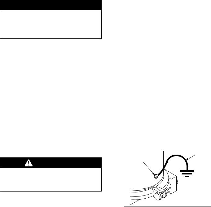
DSurge suppressor: Secure a ground wire (Y) to the surge suppressor with the grounding screw (Z) located on the side of the housing. See Fig. 1. Connect the clamp end of the ground wire to a true earth ground. To order a ground wire and clamp, order Part No. 208950.
DAir and fluid hoses: Use only grounded hoses with a maximum of 500 ft (150 m) combined hose length to ensure grounding continuity.
DAir compressor: Follow the manufacturer’s recommendations.
DAll solvent pails used when flushing: Follow the local code. Use only metal pails, which are conductive. Do not place the pail on a nonconductive surface, such as paper or cardboard, which interrupts the grounding continuity.
DFluid supply container: Follow the local code.
Y
Z
Fig. 1 |
0942 |
|
4308178

Installation
The installation shown below is only a guide for selecting and installing system components; it is not an actual system design. Contact your Graco distributor for assistance in planning a system to suit your needs.
|
|
KEY |
|
|
|
|
|
A |
Surge suppressor |
J |
Air regulator |
|
|
B |
Air pressure gauge |
K |
Air Filter |
|
|
C |
Fluid supply line |
L |
Bleed-type master air valve |
|
|
D |
Fluid outlet line |
|
(for accessories) |
|
|
E |
Air supply line |
M |
Surge suppressor ground wire |
|
|
F |
Husky 715 pump |
|
(required) |
|
|
G |
Fluid drain valve |
N |
Pump ground wire |
|
|
H |
Bleed-type master air valve |
|
(required) |
|
|
|
(required for pump and surge |
|
|
|
|
|
suppressor) |
|
G |
L |
K |
J H |
F |
|
|
|
|
||||
N
C
M
E
A B
D
DETAIL A: Venting Exhaust Air to a Remote Container
grounded air exhaust hose |
|
|
container |
|
for remote |
muffler |
air exhaust |
0906
308178 5

Installation
General Information
The surge suppressor uses air pressure and a diaphragm to maintain a consistent fluid outlet pressure from a double diaphragm or low-pressure reciprocating pump. During normal flow, the suppressor air pressure and fluid pressure are in equilibrium. A sharp increase in fluid pressure causes the air inlet port to open, increasing air pressure on the diaphragm and returning the system to equilibrium. Conversely, a sharp decrease in fluid pressure causes the air exhaust port to open, decreasing air pressure on the diaphragm and allowing the system to return to equilibrium.
Installation
1.Read this entire manual before installing or operating the surge suppressor.
2.The surge suppressor fluid inlet must be connected to the pump’s fluid outlet. If the pump is aluminum or steel, the surge suppressor may be plumbed directly to the outlet, using 3/4 npt fittings. If the pump is acetal or polypropylene, place the surge suppressor on the floor or some other solid, level surface near the pump, and connect the surge suppressor inlet to the pump outlet with a 3/4” ID hose and 3/4 npt fittings.
 CAUTION
Do not plumb the surge suppressor directly onto the fluid outlet of an acetal or polypropylene pump. Those pumps cannot support the weight of the suppressor and will suffer damage or rupture.
3.Connect an air line from the pump’s air regulator to the air inlet of the surge suppressor. In systems using a 1:1 ratio pump, the air pressure supplied to the suppressor will be the same as that supplied to the pump.
4.Use a compatible, liquid thread sealant on all male threads. Tighten all connections firmly to avoid air or fluid leaks.
 CAUTION
To avoid pump damage, do not overtighten the fittings to the pump.
Air Exhaust Ventilation
 WARNING
Be sure to read TOXIC FLUID HAZARD and FIRE AND EXPLOSION HAZARD on page 3, before operating this equipment.
Be sure the system is properly ventilated for your type of installation. When pumping flammable or hazardous fluids, you must vent the surge suppressor exhaust air to a safe place, away from people, animals, food handling areas, and all sources of ignition. If the diaphragm ruptures, the fluid will be exhausted along with the air. Place a container at the end of the air exhaust line to catch the fluid. See Detail A on page 5.
The minimum size for the air exhaust hose is 3/8 in. (10 mm) ID x 15 ft (4.6 m). If a longer hose is required, use a larger diameter hose.
1.Remove the muffler from the surge suppressor exhaust port. Install an exhaust hose in the exhaust port, and connect the muffler to the other end of the hose. Avoid sharp bends or kinks in the hose. See Detail A on page 5.
2.Place a container at the end of the air exhaust line to catch fluid in case the diaphragm ruptures.
 WARNING
Never operate the surge suppressor without the muffler or an air exhaust line installed in the air exhaust port. If the air exhaust port is left open and the diaphragm shaft works loose from the bolt, the shaft could be propelled out of the housing, causing injury.
6308178
 Loading...