


ACVC9
C
US
®
Copyright ©2009-2010 Goodman Manufacturing Company, L.P.
RT6612021 Rev. 3
August 2010
This manual is to be used by qualified, professionally trained HVAC technicians only. Goodman does
not assume any responsibility for property damage or personal injury due to improper service
procedures performed by an unqualified person.
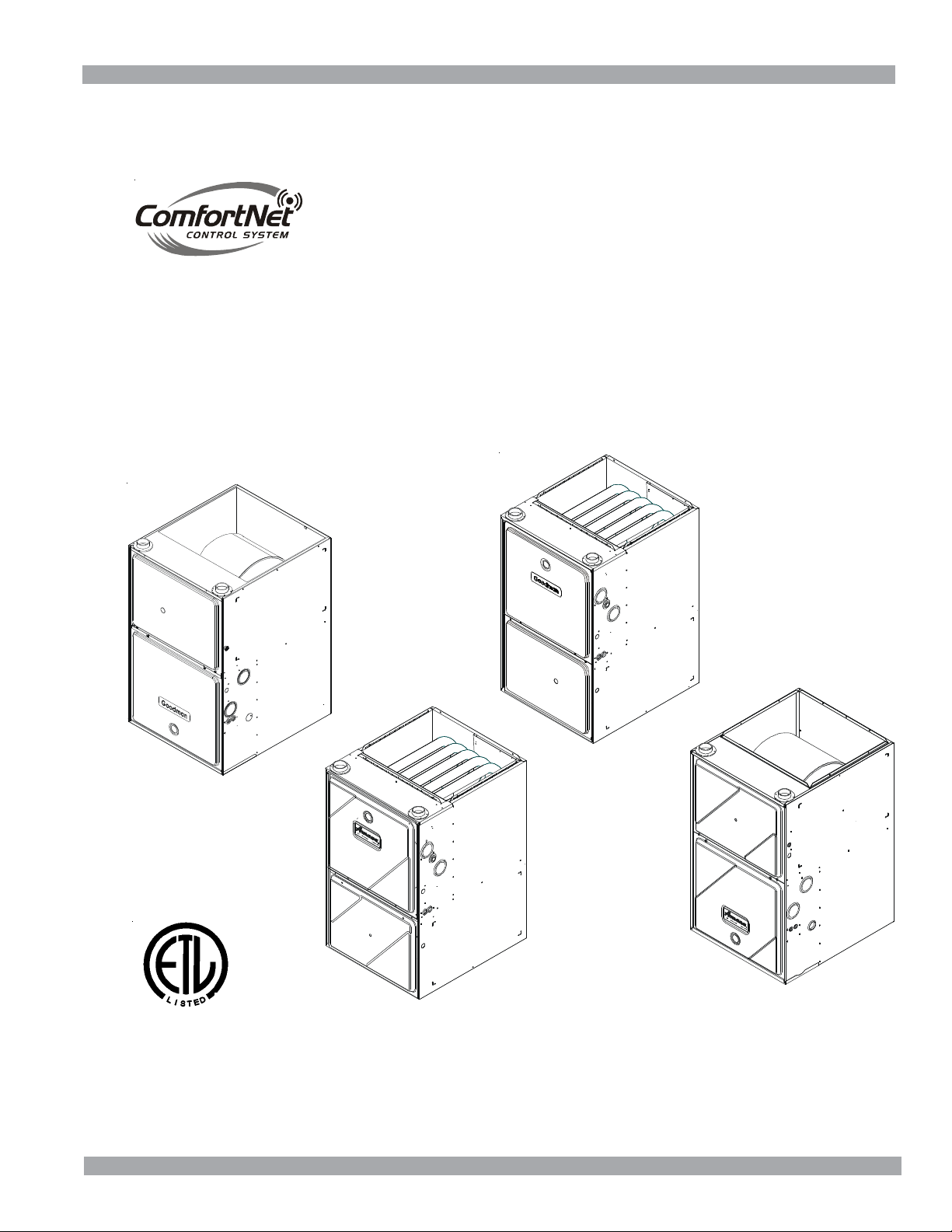
ACVC9/AMVC95
GCVC9/GMVC95
90%-95% Gas Furnace Unit s
• Refer to Service Manual RS6200004 for installation, operation, and troubleshooting information.
• All safety information must be followed as provided in the Service Manual.
• Refer to the appropriate Parts Catalog for part number information.
• Models listed on page 3.
TECHNICAL MANUTECHNICAL MANU
TECHNICAL MANUTECHNICAL MANU
TECHNICAL MANU
ALAL
ALAL
AL
TM
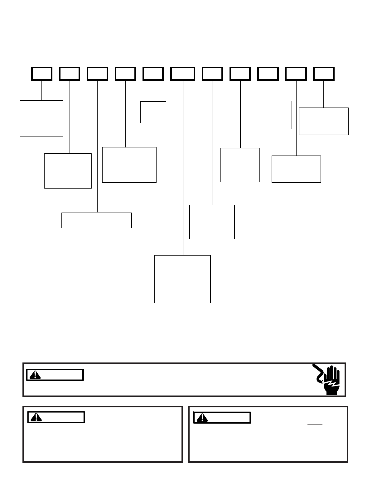
PRODUCT IDENTIFICATION
2
The model and manufacturing number are used for positive identification of component parts used in manufacturing.
Please use these numbers when requesting service or parts information.
WARNING
WARNING
HIGH VOLTAGE!
Disconnect ALL power before servicing or installing this unit. Multiple power
sources may be present. Failure to do so may cause property damage, personal
injury or death.
Installation and repair of this unit
should be performed
ONLY by indi-
viduals meeting the requirements of an "entry level tech-
nician", at a minimum, as specified by the Air-Conditioning,
Heating, and Refrigeration Institute (AHRI). Attempting to
install or repair this unit without such background may
result in product damage, personal injury or death.
Goodman will not be responsible
for any injury or property damage
arising from improper service or service procedures. If
you install or perform service on this unit, you assume
responsibility for any personal injury or property damage
which may result. Many jurisdictions require a license to
install or service heating and air conditioning equipment.
WARNING
WARNING
WARNING
WARNING
GCVC90704CXAA
FURNACE TYPE:
V : Var iable Speed
SUP PLY TY PE :
C: Counterflow/
Horizontal
M: Upf low/
Horizontal
AFUE
9: 90%
95: 95%
PRODUCT
TYPE:
G: Goodman®
A: Amana®
Brand Gas
NOMINAL IN PUT:
045: 45,000 Btuh
070: 70,000 Btuh
071: 70,000 Btuh
090: 90,000 Btuh
091: 90,000 Btuh
115: 115,000 Btuh
CABINET
WIDTH:
B: 17-1/2"
C: 21"
D: 24-1/2"
ADDITI ONAL
FEA TU R E S:
N: Natural Gas
X: Low NOx
AIRFLOW
CAPABILITY:
3: 1200
4: 1600
5: 2000
COMMUNICATION
FEATURE:
C: 4-wire
Communication
Ready
MINOR
REVISION
LEVEL
A: Init ia l R ele a se
MAJOR
REVISION
LEVEL
A: Initial Release
3
PRODUCT IDENTIFICATION
The model and manufacturing number are used for positive identification of component parts used in manufacturing. Please
use these numbers when requesting service or parts information.
AMVC950453BXAA
AMVC950704CXAA
AMVC950905CXAA
AMVC950905DXAA
AMVC951155DXAA
ACVC90704CXAA
ACVC90905DXAA
AMVC950453BXAB
AMVC950704CXAB
AMVC950905DXAB
AMVC951155DXAB
ACVC90704CXAB
ACVC90905DXAB
ACVC950714CXAA
ACVC950915DXAA
The United States Environmental Protection Agency (“EPA”) has issued various regulations re-
garding the introduction and disposal of refrigerants introduced into this unit. Failure to follow
these regulations may harm the environment and can lead to the imposition of substantial fines.
These regulations may vary by jurisdiction. Should questions arise, contact your local EPA office.
WARNING
WARNING
Do not connect or use any device
that is not design certified by
Goodman for use with this unit.
Serious property damage, personal injury, reduced unit
performance and/or hazardous conditions may result
from the use of such non-approved devices.
WARNING
WARNING
To prevent the risk of property
damage, personal injury, or death,
do not store combustible materials or use gasoline or
other flammable liquids or vapors in the vicinity of this
appliance.
WARNING
WARNING
GMVC950453BXAA
GMVC950704CXAA
GMVC950905CXAA
GMVC950905DXAA
GMVC951155DXAA
GCVC90704CXAA
GCVC90905DXAA
GCVC91155DXAA
GMVC950453BXAB
GMVC950704CXAB
GMVC950905DXAB
GMVC951155DXAB
GCVC90704CXAB
GCVC90905DXAB
GCVC91155DXAB
GCVC950714CXAA
GCVC950915DXAA
4
PRODUCT DESIGN
installation (1 or 2 pipes). The optional Combustion Air
Pipe is dependent on installation/code requirements and
must be 2” or 3” diameter PVC.
2. Line voltage wiring can enter through the right or left side
of the furnace. Low voltage wiring can enter through the
right or left side of furnace.
3. Conversion kits for propane gas and high altitude natural
and propane gas operation are available. See High Alti-
tude Derate chart for details.
4. Installer must supply the following gas line fittings, de-
pending on which entrance is used:
Left -- Two 90° Elbows, one close nipple, straight pipe
Right -- Straight pipe to reach gas valve.
Accessibility Clearances (Minimum)
POSITION* FRONT SIDES REAR TOP FLUE FLOOR
Upflow30010C
Horizontal Alcove 6 0 4 0 C
*= All positioning is determined as installed unit is view ed from the fr ont.
C= If pla ced on combustible floor, floor MUST be wo od only.
POSITION* FRONT SIDES REAR TOP FLUE FLOOR
Upflow10010NC
Horizontal Alcove 6 0 4 0 C
*= All positioning is determined as installed unit is view ed from the fr ont.
C= If pla ced on combustible floor, floor MUST be wo od only.
*MVC95* MINI MUM CLEARANCES TO COMBUSTIBLE MATERIALS
(INCHES)
NC= For in sta l al tion on non-c ombusti bl e floors only. A combus tibl e
subb ase must be used for ins tall ations on co m bustible fl oor i ng.
*CVC9 MINIMUM CLEARANCES TO COMBUSTIBLE MATERIALS
(INCHES)
NC= For in sta l al tion on non-c ombusti bl e floors only. A combus tibl e
subb ase must be used for ins tall ations on co m bustible fl oor i ng.
Alcove Illustration
REAR
S
I
D
E
S
I
D
E
A
LCOVE
24" at front is required for servicing or cleaning.
Note: In all cases accessibility clearance shall take
precedence over clearances from the enclosure where
accessibility clearances are greater. All dimensions are
given in inches.
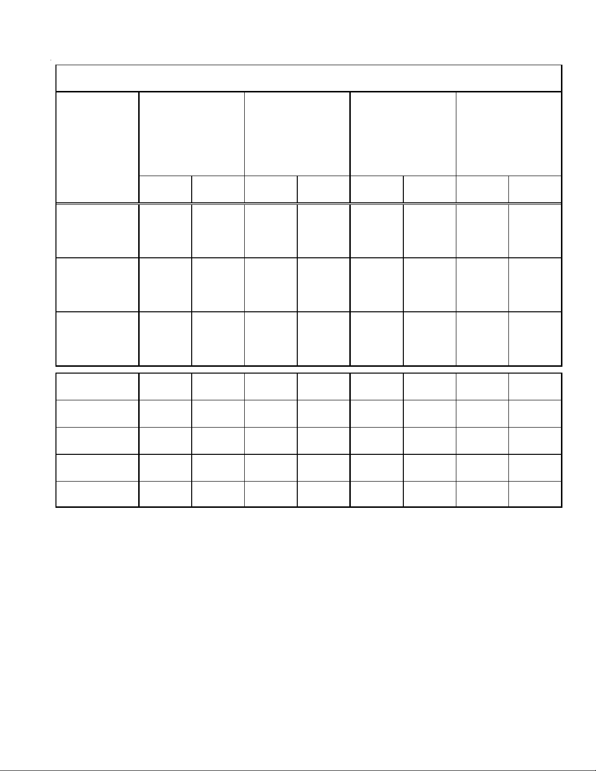
High Altitude Derate
When this furnace is installed at high altitude, the appropri-
ate High Altitude orifice kit must be installed. This is re-
General Operation
Models covered by this manual come with a new 4-wire com-
municating PCB. When paired with a compatible communi-
cating indoor unit and a CTK01AA communicating thermo-
stat, these models can support 4-wire communication pro-
tocol and provide more troubleshooting information. These
models are also backward compatible with the legacy ther-
mostat wiring.
The GCVC9, GCVC95, GMVC95, AMVC95, ACVC9 and
ACVC95 furnaces are equipped with an electronic ignition
device to light the burners and an induced draft blower to
exhaust combustion products.
An interlock switch prevents furnace operation if the blower
door is not in place. Keep the blower access doors in place
except for inspection and maintenance.
These furnaces are also equipped with a self-diagnosing elec-
tronic control module. In the event a furnace component is
not operating properly, the control module's dual 7-segment
LED's will display an alpha-numeric code, depending upon
the problem encountered. These LED's may be viewed
through the observation window in the blower access door.
Refer to the Troubleshooting Chart for further explanation of
the LED codes and Abnormal Operation - Integrated Igni-
tion Control section in the Service Instructions for an expla-
nation of the possible problem.
The rated heating capacity of the furnace should be greater
than or equal to the total heat loss of the area to be heated.
The total heat loss should be calculated by an approved
method or in accordance with “ASHRAE Guide” or “Manual
J-Load Calculations” published by the Air Conditioning Con-
tractors of America.
*Obtain from: American National Standards Institute 1430
Broadway New York, NY 10018
Location Considerations
• The furnace should be as centralized as is practical
with respect to the air distribution system.
• Do not install the furnace directly on carpeting, tile, or
combustible material other than wood flooring.
• When suspending the furnace from rafters or joists,
use 3/8" threaded rod and 2” x 2” x 1/8” angle as
shown in the Installation and Service Instructions. The
length of the rod will depend on the application and
clearance necessary.
• When installed in a residential garage, the furnace
must be positioned so the burners and ignition source
are located not less than 18 inches (457 mm) above
the floor and protected from physical damage by ve-
hicles.
Notes:
1. Installer must supply one or two PVC pipes: one for com-
bustion air (optional) and one for the flue outlet (required).
Vent pipe must be either 2” or 3” in diameter, depending
upon furnace input, number of elbows, length of run and
5
PRODUCT DESIGN
quired due to the natural reduction in the density of both the
gas fuel and combustion air as altitude increases. The kit
will provide the proper design certified input rate within the
specified altitude range.
High altitude kits are purchased according to the installa-
tion altitude and usage of either natural or propane gas. Refer
to the chart above for a tabular listing of appropriate altitude
ranges and corresponding manufacturer’s high altitude Natu-
ral Gas and Propane Gas kits. For a tabular listing of appro-
priate altitude ranges and corresponding manufacturer's High
Altitude Pressure Switch kits, refer to either the Pressure
Switch Trip Points & Usage Chart in this manual or the Ac-
cessory Charts in Service Instructions.
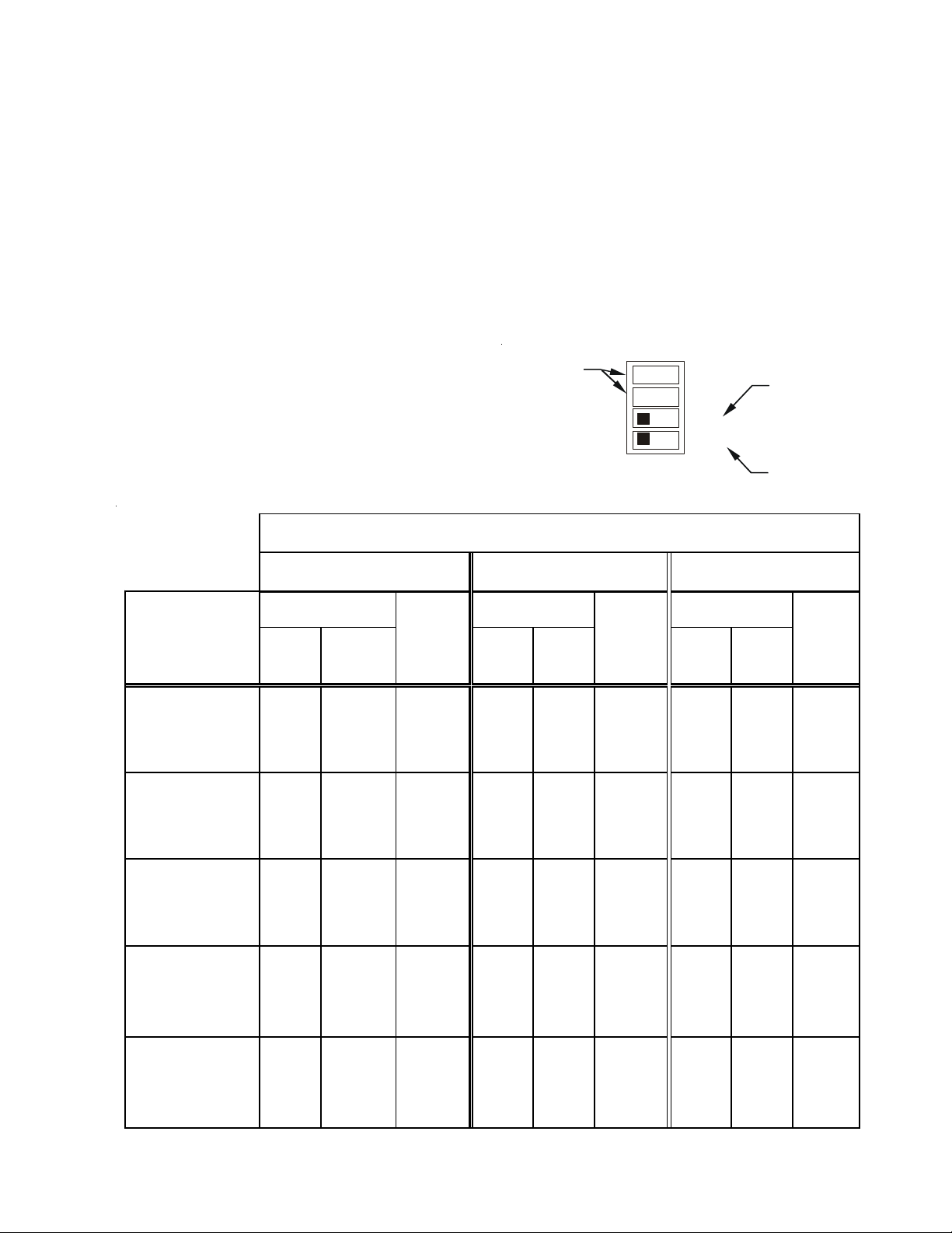
Single Stage Thermostat
A single-stage thermostat with only one heating stage may
be used to control this furnace. The application of a single-
stage thermostat does not offer “true” thermostat-driven two-
stage operation, but provides a timed transition from low to
high fire. The furnace will run on low stage for a fixed period
of time before stepping up to high stage to satisfy the
thermostat’s call for heat. The delay period prior to stepping
up can be set at either a fixed 5 minute time delay or a load
based variable time between 1 and 12 minutes (AUTO mode).
If the AUTOmode is selected, the control averages the cycle
times of the previous three cycles and uses the average to
determine the time to transition from low stage to high stage.
To use a single-stage thermostat, turn off power to the fur-
nace, move the thermostat selection DIP switch to the OFF
position. Set the desired transition time by setting the tran-
sition delay DIP switch to the desired ON/OFF position. Turn
power back on. Refer to the following figure.
3
4
Thermostat
Stage Delay
Move to the ON position
to select two-stage
thermostat or OFF to
select single stage
thermostat
Move to the ON position
to select A u to transition
delay or OFF for 5 minute
transition delay
Heat OFF Delay
DIP Switches
ON OFF
S1
1
LPM-05* supports White-Rodgers 2-stage valves only
2
LPM-06* supports Honeywell and White-Rodgers 2-stage valves
Natural
Propane
Natural
Propane
Natural
Propane
GMVC950453BX*
GMVC950704CX*
AM VC950453B X*
AM VC950704 C X*
No
Change
LPM-05*
(1)
LPM-06*
(2)
#55 Orifice
No
Chan ge
HANG 13
#44
Orifice
HA LP11
#56
Orifice
HAPS28
HANG 14
#45
Orifice
HALP11
#56
Orifice
HAPS28
GMVC950905CX*
AM VC950905 C X*
No
Change
LPM-05*
(1)
LPM-06*
(2)
#55 Orifice
No
Chan ge
N/A N/A N/A N/A N/A N/A
GMVC950905DX*
GMVC951155DX*
AM VC950905 D X*
AM VC951155 D X*
No
Change
LPM-05*
(1)
LPM-06*
(2)
#55 Orifice
No
Chan ge
HANG 13
#44
Orifice
HA LP11
#56
Orifice
HAPS29
HANG 14
#45
Orifice
HALP11
#56
Orifice
HAPS29
GCVC90704CX*
GCVC90905DX*
GCVC91155DX*
AC VC90704CX*
AC VC90905DX*
No
Change
LPM-05*
(1)
LPM-06*
(2)
#55 Orifice
No
Chan ge
HANG 13
#44
Orifice
HA LP11
#56
Orifice
HAPS29
HANG 14
#45
Orifice
HALP11
#56
Orifice
HAPS31
GC VC950714 C X*
GC VC950915 D X*
ACVC950714CX*
ACVC950915DX*
No
Change
LPM-05*
(1)
LPM-06*
(2)
#55 Orifice
No
Chan ge
N/A N/A N/A N/A N/A N/A
ID Blw r
Pressure
Switch
G a s Orifices
9 ,001 - 11,000 Feet
"STANDARD" and "HIGH ALTITUDE" KITS
Furnace
ID Blwr
Pressure
Switch
Gas Orifices
0 - 7,000 Feet
(Standard Altitude)
7,001 - 9, 00 0 Feet
Gas Orifices
ID Blwr
Pressure
Switch
COMPONENT IDENTIFICATION
6
Counterflow /HorizontalUpflow/Horizontal
1 Two-Stage Gas Valve
2 Gas Line Entrance (Alternate)
3 Pressure Switch(es)
4 Gas Manifold
5 Combustion Air Intake Connection
6 Hot Surface Igniter
7 Rollout Limit
8 Burners
9 Flame Sensor
10 Flue Pipe Connection
11 Flue Pipe
12 Primary Limit
13 Gas Line Entrance
14 Flue Pipe Connection (Alternate)
15 Rubber Elbow
16 Two-Speed Induced Draft Blower
17 Electrical Connection Inlets (Alternate)
18 Coil Front Cover Pressure Tap
19 Coil Front Cover Drain Port
20 Drain Line Penetrations
21 Drain Trap
22 Blower Door Interlock Switch
23 Inductor (Not All Models)
24 Two-Stage Integrated Control Module
(with fuse and diagnostic LED)
25 24 Volt Thermostat Connections
26 Transformer (40 VA)
27 ECM Variable Speed Circulator Blower
28 Auxiliary Limit
29 Junction Box
30 Electrical Connection Inlets
31 Coil Front Cover
32 Combustion Air Inlet Pipe (*CVC9/95 only)
BLOWER COMPARTMENT
1
9
7
8
7
4
6
12
13
21
20
19
18
31
3
24
23
25
32
5
26
27
10
28
3
15
14
16
18
19
20
2
11
17
30
29
BLOWER COMPARTMENT BURNER COMPARTMENT
1
2
3
4
5
6
7
8
7
9
10
11
3
12
13
14
15
16
18
19
20
23
25
26
27
28
21
20
19
18
31
17
*
*
*
*
*
*
*
*
*
7
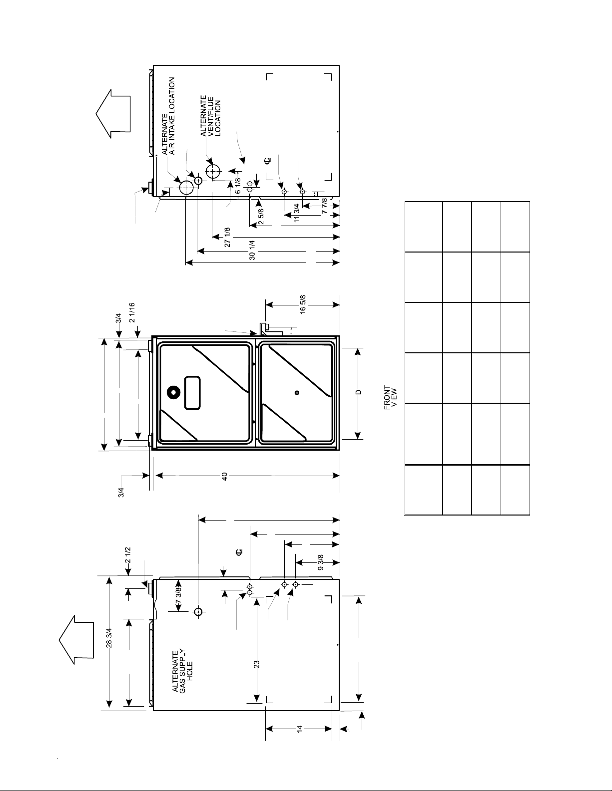
PRODUCT DIMENSIONS
GMVC95/AMVC95___X*
NOTE: Airflow area will be reduced by approximately 18% if duct flanges are not unfolded. This could cause performance issues and noise issues.
AIR
DISCHARGE
IR
DISCHARGE
LOW VOLTAGE
ELECTRICAL HOLE
HIGH VOLTAGE
ELECTRICAL HOLE
SIDE CUT-OUT
LEFT S I D E
VIEW
SIDE CUT-OUT
HIGH VOLTAGE
ELECTRICAL HOLE
LOW VOLTA GE
ELECTRICAL HOLE
RIGHT SIDE
DRAIN LINE
HOLES
STANDARD GAS
SUPPLY HOLE
DRAIN
TRAP
19 3/4
AIR INTAKE
PIPE
2" PVC
LEFT SIDE
DRAIN LINE
HOLES
1 3/4
DRAIN
TRAP
1 1/2
1 5/8
30 1/4
11 3/4
19 3/16
BOTTOM KNOCK-OUT
23 9/16
2 11 /1 6
VENT/FLUE PIPE
2" PVC
RIGHT SIDE
VIEW
2 5/8
32 13/16
19 3/16
1 3/4
CONDENSATE
DRAIN TRAP
w/ 3/4" PVC
DISCHARGE
(RIGHT OR
LEFT SIDE)
2
BOTTOM KNOCK-OUT
C
B
A
(DISCHARGE AIR)
4 1/8
CABINET
SIZE
UNITSABCD
SM A LL 0453BX* 17 1/2 15 12 3/8 12 5/8
MEDIUM
0704CX*
0905CX*
21 19 16 3/8 14 5/8
LARGE
0905DX*
1155DX*
24 1/2 23 20 3/8 18 5/8
All dim ens ions are in inc hes .
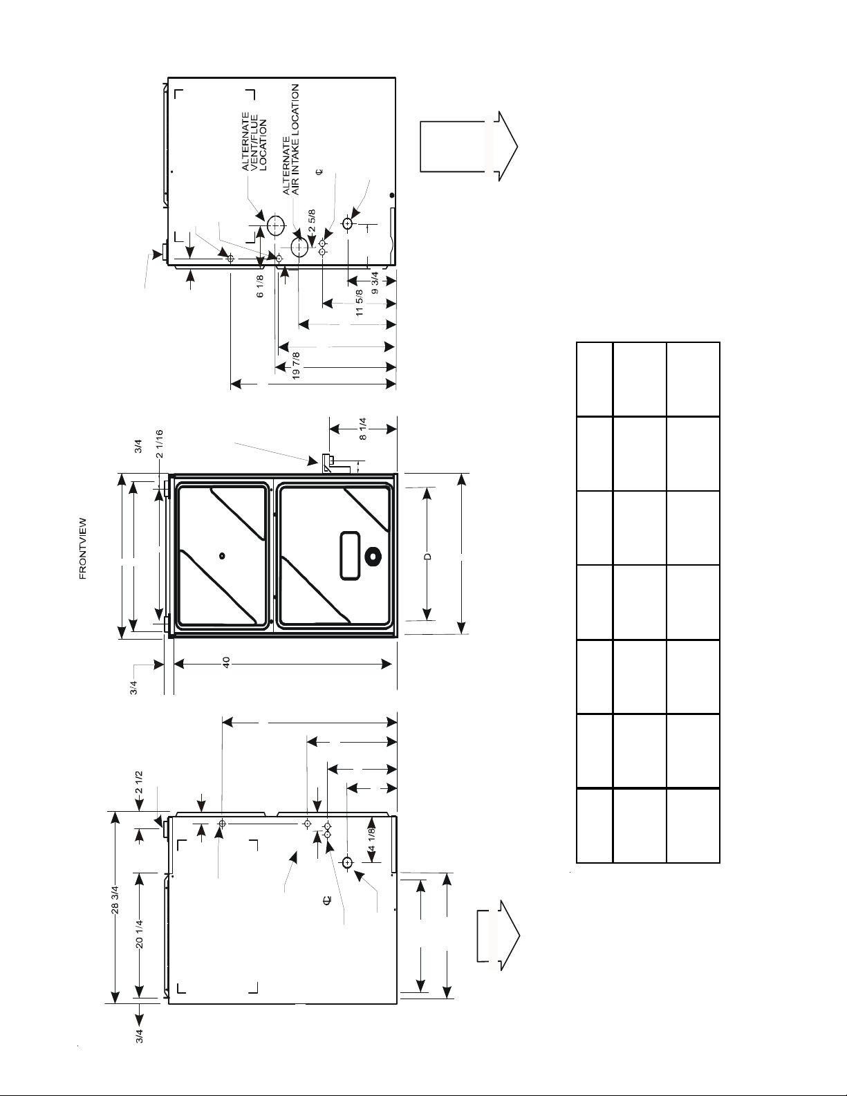
PRODUCT DIMENSIONS
8
GCVC9/ACVC9_____X*
NOTE: Airflow area will be reduced by approximately 18% if duct flanges are not unfolded. This could cause performance issues and noise issues.
LOW VOLTAGE
ELECTRICAL HOLE
AIR INTAKE
PIPE
2" PVC
LEFT SIDE
DRAIN LINE
HOLES
DRAIN
TRAP
28 5/1 6
11 1/2
9 13/ 16
15 1/2
UNFOLDED FLANGES
1 3/4
18 5/8
2 5/8
HIGH VOLTAGE
ELECTRICAL HOLE
20 5/3 2
2
UNFOLDE D FLANGES
DISCHARGE AIR
E
CONDENSATE
DRAIN TRAP
w/ 3/4" PVC
DISCHARGE
(RIGHT OR
LEFT SIDE)
FOLDED FLANGES
(RETURN AIR)
A
HIGH VOLTAGE
ELECTRICAL HOLE
LOW VOLTAGE
ELECTRICAL HOLE
RIGHT SIDE
DRAIN LINE
HOLES
VENT/FLUE PIPE
2" PVC
DRAIN
TRAP
LTERNAT E GAS
SUPPLY HOLE
1 3/4
28 5/16
18 13/16
14
STANDARD GAS
SUPPLY HOLE
FOLDED FLANGES
2 11/16
C
7 3/8
AIR
DISCHARGE
IR
DISCHARGE
B
CABINET
SIZE
UNITSABCDE
MEDIUM
0704CX*
0714CX*
21 19 16 3/8 14 5/8 17 1/ 2
LARGE
0905DX*
0915DX*
1155DX*
24 1/2 23 20 3/8 18 5/8 20 7/8
All dimensions are in inches.
9
PRODUCT DESIGN
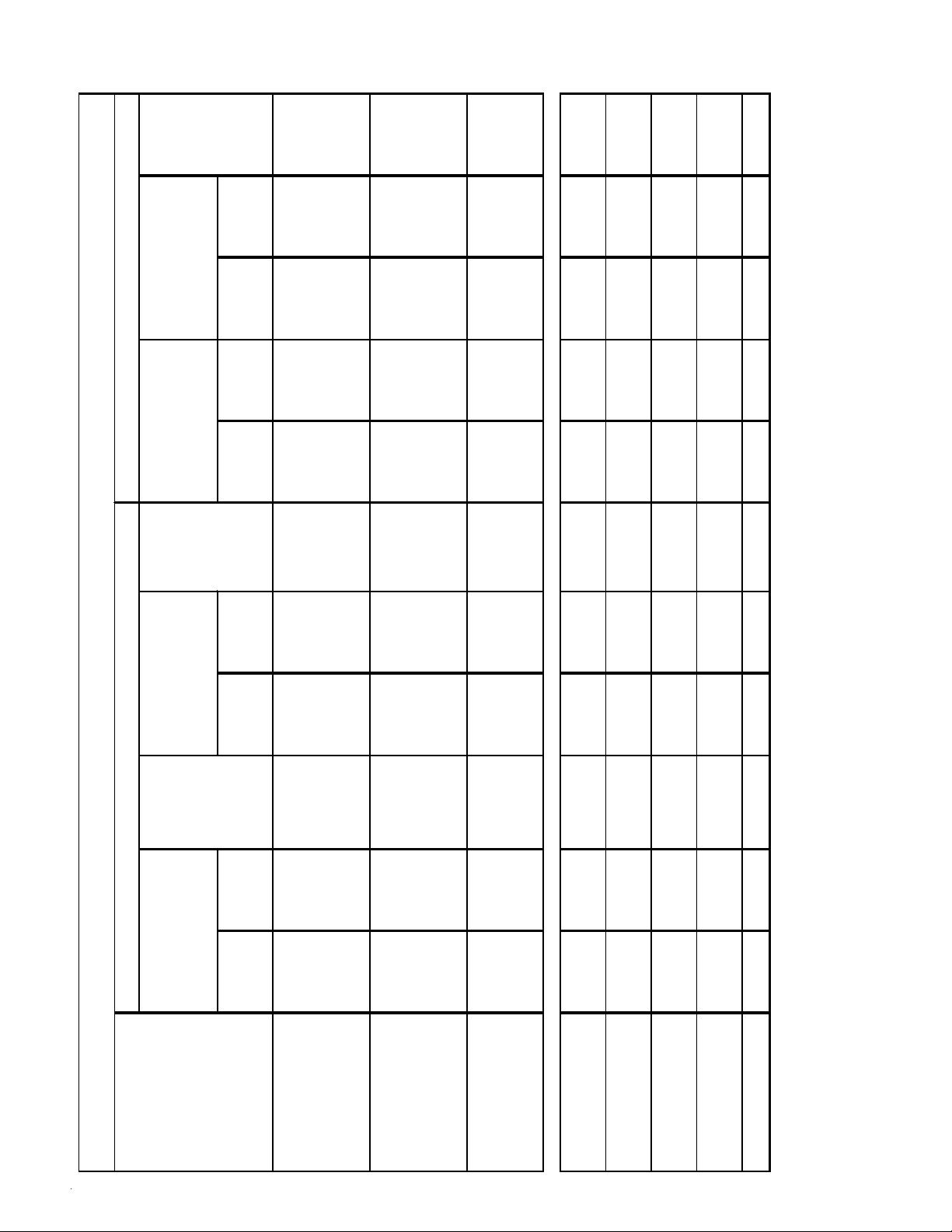
LOW FIRE HIGH FIRE LOW FIRE HIGH FIRE LOW FIRE HIGH FI RE LOW FIRE HIGH FIRE
GMVC950453BX*
GMVC950704CX*
AMVC950453BX*
AMVC950704CX*
-0.45 -0 .90 -0.50 -0.9 5 -0.25 -0.25 -0.25 -0.25
GMVC950905CX*
AMVC950905CX*
-0.75 -1.85 -.060 -1.70 -0.10 -0.10 -0.10 -0.10
GMVC950905DX*
GMVC951155DX*
AMVC950905DX*
AMVC951155DX*
-0.65 -1 .20 -0.70 -1.2 5 -0.25 -0.25 -0.25 -0.25
GCVC90704CX*
ACVC90704CX*
-0.35 -0 .70 -0.20 -0.5 5 -0.52 -0.52 -0.37 -0.37
GCVC950714CX*
ACVC950714CX*
-0.95 -1 .75 -1.00 -1.8 0 -0.10 -0.10 -0.10 -0.10
GCVC90905DX*
ACVC90905DX*
-0.35 -0 .70 -0.20 -0.5 5 -0.52 -0.52 -0.37 -0.37
GCVC950915DX*
ACVC950915DX*
-0.95 -1 .75 -1.00 -1.8 0 -0.10 -0.10 -0.10 -0.10
GCVC91155DX*
-0.35 -0 .70 -0.20 -0.5 5 -0.52 -0.52 -0.37 -0.37
(2) Data given is le ast negative pr essure require d for pressure switch to remain closed.
Note: T he typical sea level negative pressure data represents the minimum pressures expected. Shorter length of flue pipe or sing le pipe systems compared to
dual pipe systems should show higher (greater negative) pressu res.
PRESS URE SWIT CH TRIP POINTS AND US AGE CHART
NEGATIVE PRESSURE
ID BLO WER
WITH FLUE
NOT FIRING
TYPICAL SEA LEVEL
DATA
(1)
NEGATIVE PRESSURE
ID BLO WER
WITH FLUE
FIRING
TYPICAL SEA LEVEL
DATA
(2)
NEGATIVE PRESSURE
COIL COVER
WITH FLUE
NOT FIRING
TYPICAL SEA LEVEL
DATA
(1)
NEGATIVE PRESSURE
COIL COVER
WITH FLUE
FIRING
TYPICAL SEA LEVEL
DATA
(2)
MODEL
(1) Data given is least negativ e press ur e required for pressure switch to close.
10
PRODUCT DESIGN
LOW FIRE HIGH FIRE LOW FIRE HIGH FIRE LOW FIRE HIGH FIRE LOW FIRE HIGH FIRE
GMVC950453BX*
GMVC950704CX*
AMVC950453BX*
AMVC950704CX*
-0.10 -0.10 20197308 -0.30 -0.75 11177113 -0.10 -0.10 -0.22 -0.55
HAPS 28
11177115
GMVC950905CX*
AMVC950905CX*
-0.10 -0.10 0130F00070 -0.60 -1.70 0130F00111 N/A N/A N/A N/A N/A
GMVC950905DX*
GMVC951155DX*
AMVC950905DX*
AMVC951155DX*
-0.10 -0.10 20197308 -0.50 -1.10 11177114 -0.10 -0.10 -0.38 -0.82
HAPS 29
11177116
GCVC90704CX*
ACVC9070 4CX*
-0.37 -0.37 20197313 -0.20 -0.55 11177118 -0.37 -0.37 -0.15 -0.30 HAPS31
GCVC950714CX*
ACVC950714CX *
-0.10 -0.10 0130F00070 -0.80 -1.60 0130F00100 N/A N/A N/A N/A N/A
GCVC90905DX*
ACVC9090 5DX*
-0.37 -0.37 20197313 -0.20 -0.55 11177118 -0.37 -0.37 -0.15 -0.30 HAPS31
GCVC950915DX*
ACVC950915DX *
-0.10 -0.10 0130F00070 -0.80 -1.60 0130F00100 N/A N/A N/A N/A N/A
GCVC91155DX*
-0.37 -0.37 20197313 -0.20 -0.55 11177118 -0.37 -0.37 -0.15 -0.30 HAPS31
PRESSURE SWITCH TRIP POINTS AND USAGE CHART
Note:
All installations above 7,000 ft. require a pressure switch change. For installations in Canada the *MVC95 & *CVC9/95 furnaces are certified only to 4500 ft.
TRIP POINT
COIL COVER
PRESSURE SWITCH
TRIP POINT
COIL COVER
PRESSURE SWITCH
TRIP POINT
ID BLO WER
PRESSURE SWITCH
COIL COVER
PRESSURE
SWITCH
PART #
Note:
Replacement pressure switch number is listed below high altitude kit number.
Note:
All negative pressure readings are in inches of water column (" w.c.).
0 to 7,000 ft.
MODEL
TRIP POINT
ID BLOWE R
PRESSURE SWITCH
HIGH
ALTITUDE
KIT
7,001 ft. to 11,000 ft.
ID BLOWER
PRESSURE
SWITCH
PART #
11
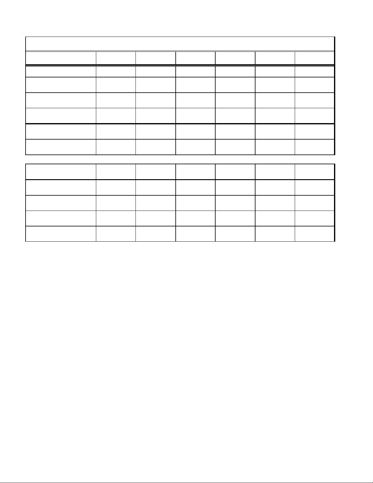
PRODUCT DESIGN
Part Number
20162903 20162904 20162905 20162907 20162908 0130F00105
Open Setting (°F)
160 150 145 155 170 130
GMVC950453BX*
AMVC950453BX*
--- --- 1 --- --- ---
GMVC950704CX*
AMVC950704CX*
--- --- --- 1 --- ---
GMVC950905CX*
AMVC950905CX*
--- --- --- --- --- 1
GMVC950905DX*
AMVC950905DX*
--- --- 1 --- --- ---
GMVC951155DX*
AMVC951155DX*
--- 1 --- --- --- ---
GCVC90704CX*
ACVC907 04CX*
1 --- --- --- --- ---
GCVC95071 4CX*
ACVC950 714CX*
--- 1 --- --- --- ---
GCVC90905DX*
ACVC909 05DX*
--- -- - --- --- 1 ---
GCVC95091 5DX*
ACVC950 915DX*
--- -- - --- --- --- 1
GCVC91155DX*
---- ---- 1 ---- ---- ---
PRIMARY LIMIT
Part Number 10123512 10123517 10123518 10123533 10123534 10123537
Open Setting (°F)
325 210 170 200 220 190
GMVC950453BX*
AMVC950453BX*
--- --- 1 --- --- ---
GMVC950704CX*
AMVC950704CX*
--- --- --- 2 --- ---
GMVC950905CX*
AMVC950905CX*
--- --- --- 2 --- ---
GMVC950905DX*
AMVC950905DX*
--- --- --- --- --- 2
GMVC951155DX*
AMVC951155DX*
--- --- --- 2 --- ---
GCVC90704CX*
ACVC90704CX*
---- --- --- --- 2 ---
GCVC950714CX*
ACVC950714CX*
---- 2 ---- ---- ---- ----
GCVC90905DX*
ACVC90905DX*
--- 2 --- --- --- ---
GCVC950915DX*
ACVC950915DX*
--- 2 --- --- --- ---
GCVC91155DX*
---- 2 ---- ---- ---- ---
ROLLOUT LIMIT SWITCHES
12
PRODUCT DESIGN
Part Number 10123534 10123535 10123537 10123536 10123533 0130F00038
Ope n Setting (°F)
220 150 190 180 200 120
GMVC950453BX*
AMVC950453BX*
--- 2 --- --- --- ---
GMVC950704CX*
AMVC950704CX*
------2 ---------
GMVC950905CX*
AMVC950905CX*
--- --- --- --- --- 2
GMVC950905DX*
AMVC950905DX*
--- --- --- 2 --- ---
GMVC951155DX*
AMVC951155DX*
--- --- --- ---
2---
GCVC90704CX*
ACVC90704CX*
2 --- --- --- -- - ---
GCVC950714CX*
ACVC950714CX*
--- --- --- --- --- 2
GCVC90905DX*
ACVC90905DX*
--- --- --- 2 --- ---
GCVC950915DX*
ACVC950915DX*
--- --- --- --- --- 2
GCVC911555DX*
--- --- --- 2 --- ---
AUXILIARY LIMIT SWITCHES
 Loading...