


Triplex Ceramic
Plunger Pump
Operating Instructions/
Repair and Service
Models Manual
LP122A Series/LP123/LP255
For Models:
LP122A
LP122A-3100
LP122A-4000
LP123
LP255
|
Contents: |
|
|
Installation Instructions: |
page 2 |
|
Pump Specifications: |
page 3-4 |
|
Exploded View: |
page 5 |
|
Parts List: |
page 6 |
|
Kit List/Torque |
|
|
Specifications: |
page 7 |
|
Repair Instructions: |
pages 8-10 |
|
Dimensions: |
page 11 |
Updated 5/01 |
Warranty Information: |
back page |
|
|
INSTALLATION INSTRUCTIONS
Installation of the Giant Industries, Inc., pump is not a complicated procedure, but there are some basic steps common to all pumps. The following information is to be considered as a general outline for installation. If you have unique requirements, please contact Giant Industries, Inc. or your local distributor for assistance.
1. The pump should be installed flat on a base to a maximum of a 15 degree angle of inclination to ensure optimum lubrication.
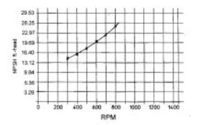
2. The inlet to the pump should be sized for the flow rate of the pump with no unnecessary restrictions that can cause cavitation. Teflon tape should be used to seal all joints. If pumps are to be operated at temperatures in excess of 1600 F, it is important to insure a positive head to the pump to prevent cavitation. See NPSH curve.
3. The discharge plumbing from the pump should be properly sized to the flow rate to prevent line pressure loss to the work area. It is essential to provide a safety bypass valve between the pump and the work area to protect the pump from pressure spikes in the event of a blockage or the use of a shut-off gun.
4. Use of a dampener is necessary to minimize pulsation at drive elements, plumbing, connections, and other system areas. The use of a dampener with Giant Industries, Inc. pumps is optional, although recommended by Giant Industries, Inc. to further reduce system pulsation. Dampeners can also reduce the severity of pressure spikes that occur in systems using a shut-off gun. A dampener must be positioned downstream from the unloader.
5. Crankshaft rotation on Giant Industries, Inc. pumps should be made in the direction designated by the arrows on the pump crankcase. Reverse rotation may be safely achieved by following a few guidelines available upon request from Giant Industries, Inc. Required horsepower for system operation can be obtained from the charts on pages 3.
6. Before beginning operation of your pumping system, remember: Check that the crankcase and seal areas have been properly lubricated per recommended schedules. Do not run the pump dry for extended periods of time. Cavitation will result in severe damage. Always remember to check that all plumbing valves are open and that pumped media can flow freely to the inlet of the pump.
Finally, remember that high pressure operation in a pump system has many advantages. But, if it is used carelessly and without regard to its potential hazard, it can cause serious injury.
IMPORTANT OPERATING CONDITIONS
Failure to comply with any of these conditions invalidates the warranty.
1. Prior to initial operation, add oil to the crankcase so that oil level is between the two lines on the oil dipstick. DO NOT OVERFILL.
Use SAE 90 Industrial gear oil
Crankcase oil should be changed after the first 50 hours of operation, then at regular intervals of 500 hours or less depending on operating conditions.
2.Pump operation must not exceed rated pressure, volume, or RPM. A pressure relief device must be installed in the discharge of the system.
3.Acids, alkalines, or abrasive fluids cannot be pumped unless approval in writing is obtained before operation from Giant Industries, Inc.
4.Run the pump dry approximately 10 seconds to drain the water before exposure to freezing temperatures.
NOTE: Contact Giant Industries for Service School Information. Phone: (419)-531-4600
2

Specifications |
|
Models LP122A Series/LP123 |
|
Volume ............................................................................................... |
Up to 39.0 GPM (147.6 l/m) |
Discharge Pressure ............................................................................ |
Up to 2000* PSI (138* Bar) |
Inlet Pressure ..................................................................................... |
Up to 90 PSI (6.2 Bar) |
Speed ................................................................................................. |
Up to 885 RPM |
Plunger Diameter ............................................................................... |
42 mm |
Stroke ................................................................................................. |
42 mm |
Crankcase Oil Capacity ..................................................................... |
116 fl.oz. |
Temperature of Pumped Fluids ......................................................... |
Up to 160oF (71oC) |
Inlet Port ............................................................................................ |
1-1/2" NPT |
Discharge Port ................................................................................... |
1" NPT |
Crankshaft Mounting ......................................................................... |
Either Side |
Shaft Rotation .................................................................................... |
Top of Pulley Towards Fluid End |
Weight................................................................................................ |
116 lbs. |
Crankshaft Diameter.......................................................................... |
35 mm |
Valve Casing - LP122A ..................................................................... |
Aluminum Bronze |
Valve Casing - LP123 ........................................................................ |
Brass |
Valve Casing - LP122A-4000 ............................................................ |
303 S.S. |
Valve Casing - LP122A-3100 ............................................................ |
Aluminum Bronze-Nickle |
Volumetric Efficiency @ 800 RPM................................................... |
0.96 |
Mechanical Efficiency @ 800 RPM.................................................. |
0.85 |
PULLEY INFORMATION
Pulley selection and pump speed are based on a 1725 RPM motor and "B" section belts. When selecting desired GPM, allow for a ±5% tolerance on pumps output due to variations in pulleys, belts and motors among manufacturers.
1.Select GPM required, then select appropriate motor and pump pulley from the same line.
2.The desired pressure is achieved by selecting the correct nozzle size that corresponds with the pump GPM.
HORSEPOWER INFORMATION
We recommend that a 1.1 service factor be specified when s electing an electric motor as the power source. To compute specific pump horsepower requirements, use the following formula:
HP = (GPM X PSI) / 1440
Pump speeds of 640 RPM and above require a minimum inlet pressure of 12 psig. Pump speeds of 805 RPM and above require a minimum inlet pressure of 14 psig.
LP122A SERIES/LP123 PULLEY SELECTION AND HORSEPOWER
REQUIREMENTS
GPM |
PUMP |
MOTOR |
RPM |
600 PSI |
800 PSI |
1000 PSI |
1300 PSI |
2000 PSI* |
|
PULLEY |
PULLEY |
||||||||
|
|
|
|
|
|
|
|||
22.3 |
12.75" |
3.95" |
500 |
9.6 |
12.7 |
15.9 |
20.7 |
31.9 |
|
24.7 |
12.75" |
4.35" |
555 |
10.6 |
14.1 |
17.6 |
22.9 |
35.3 |
|
28.5 |
12.75" |
4.95" |
640 |
12.2 |
16.3 |
20.4 |
26.5 |
40.7 |
|
30.9 |
12.75" |
5.35" |
695 |
13.2 |
17.7 |
22.1 |
28.7 |
44.1 |
|
33.4 |
12.75" |
5.75" |
750 |
14.3 |
19.1 |
23.9 |
31.0 |
47.7 |
|
35.6 |
12.75" |
6.15" |
800 |
15.3 |
20.3 |
25.4 |
33.1 |
50.9 |
|
39.4* |
12.75" |
6.50" |
885 |
16.9 |
22.5 |
28.1 |
36.6 |
56.3 |
*Intermittent duty only! - Consult factory!
3
Specifications |
|
Model LP255 |
|
Volume ............................................................................................... |
Up to 26.0 GPM (147.6 l/m) |
Discharge Pressure ............................................................................ |
Up to 2200* |
Inlet Pressure ..................................................................................... |
Up to 90 PSI |
Speed ................................................................................................. |
Up to 1000 RPM |
Plunger Diameter ............................................................................... |
32 mm |
Stroke ................................................................................................. |
42 mm |
Crankcase Oil Capacity ..................................................................... |
116 fl.oz. |
Temperature of Pumped Fluids ......................................................... |
Up to 160oF |
Inlet Port ............................................................................................ |
1-1/2" NPT |
Discharge Port ................................................................................... |
1" NPT |
Crankshaft Mounting ......................................................................... |
Either Side |
Shaft Rotation .................................................................................... |
Top of Pulley Towards Fluid End |
Weight................................................................................................ |
116 lbs. |
Crankshaft Diameter.......................................................................... |
35 mm |
Valve Casing - LP122A ..................................................................... |
Aluminum Bronze |
Valve Casing - LP123/LP255 ............................................................ |
Brass |
Valve Casing - LP122A-4000 ............................................................ |
303 S.S. |
Valve Casing - LP122A-3100 ............................................................ |
Aluminum Bronze-Nickle |
Volumetric Efficiency @ 800 RPM................................................... |
0.96 |
Mechanical Efficiency @ 800 RPM.................................................. |
0.85 |
PULLEY INFORMATION
Pulley selection and pump speed are based on a 1725 RPM motor and "B" section belts. When selecting desired GPM, allow for a ±5% tolerance on pumps output due to variations in pulleys, belts and motors among manufacturers.
1.Select GPM required, then select appropriate motor and pump pulley from the same line.
2.The desired pressure is achieved by selecting the correct nozzle size that corresponds with the pump GPM.
HORSEPOWER INFORMATION
We recommend that a 1.1 service factor be specified when s electing an electric motor as the power source. To compute specific pump horsepower requirements, use the following formula:
HP = (GPM X PSI) / 1440
LP255 PULLEY SELECTION AND HORSEPOWER REQUIREMENTS
PUMP |
MOTOR |
RPM |
GPM |
1000 PSI |
1500 PSI |
2000 PSI |
2200 PSI |
|
PULLEY |
PULLEY |
|||||||
|
|
|
|
|
|
|||
12.75" |
3.95" |
500 |
13 |
9.3 |
13.9 |
18.6 |
20.4 |
|
12.75" |
4.35" |
640 |
16.6 |
11.9 |
17.8 |
23.7 |
26.1 |
|
12.75" |
4.95" |
750 |
19.5 |
13.9 |
20.9 |
27.9 |
30.6 |
|
12.75" |
5.35" |
805 |
20.9 |
14.9 |
22.4 |
29.9 |
32.8 |
|
12.75" |
5.75" |
865 |
22.5 |
16.1 |
24.1 |
32.1 |
35.4 |
|
12.75" |
6.15" |
920 |
23.9 |
17.1 |
25.6 |
34.1 |
37.6 |
|
12.75" |
6.50" |
1000 |
26 |
18.6 |
27.9 |
37.1 |
40.9 |
*Intermittent duty only! - Consult factory!
4
 Loading...