


Diagnostic
Repair Manual
RECREATIONAL VEHICLE GENERATOR
For more information
www.guardiangenerators.com
QUIETPACT® 55/65/75
Model 4702, 4703, 4707, 4705, 4706, 4707

SAFETY
Throughout this publication, "DANGER!" and "CAUTION!" blocks are used to alert the mechanic to special instructions concerning a particular service or operation that might be hazardous if performed incorrectly or carelessly. PAY CLOSE ATTENTION TO THEM.
DANGER! UNDER THIS HEADING WILL BE FOUND SPECIAL INSTRUCTIONS WHICH, IF NOT COMPLIED WITH, COULD RESULT IN PERSONAL INJURY OR DEATH.
CAUTION! Under this heading will be found special instructions which, if not complied with, could result in damage to equipment and/or property.
These "Safety Alerts" alone cannot eliminate the hazards that they signal. Strict compliance with these special Instructions plus "common sense" are major accident prevention measures.
NOTICE TO USERS OF THIS MANUAL
This SERVICE MANUAL has been written and published by Generac to aid our dealers' mechanics and company service personnel when servicing the products described herein.
It is assumed that these personnel are familiar with the servicing procedures for these products, or like or similar products manufactured and marketed by Generac. That they have been trained in the recommended servicing procedures for these products, including the use of common hand tools and any special Generac tools or tools from other suppliers.
Generac could not possibly know of and advise the service trade of all conceivable procedures by which a service might be performed and of the possible hazards and/or results of each method. We have not undertaken any such wide evaluation. Therefore, anyone who uses a procedure or tool not recommended by Generac must first satisfy himself that neither his nor the products safety will be endangered by the service procedure selected.
All information, illustrations and specifications in this manual are based on the latest product information available at the time of publication.
When working on these products, remember that the electrical system and engine ignition system are capable of violent and damaging short circuits or severe electrical shocks. If you intend to perform work where electrical terminals could be grounded or touched, the battery cables should be disconnected at the battery.
Any time the intake or exhaust openings of the engine are exposed during service, they should be covered to prevent accidental entry of foreign material. Entry of such materials will result in extensive damage when the engine Is started.
During any maintenance procedure, replacement fasteners must have the same measurements and strength as the fasteners that were removed. Metric bolts and nuts have numbers that indicate their strength. Customary bolts use radial lines to indicate strength while most customary nuts do not have strength markings. Mismatched or incorrect fasteners can cause damage, malfunction and possible injury.
REPLACEMENT PARTS
Components on Generac recreational vehicle generators are designed and manufactured to comply with Recreational Vehicle Industry Association (RVIA) Rules and Regulations to minimize the risk of fire or explosion. The use of replacement parts that are not in compliance with such Rules and Regulations could result in a fire or explosion hazard. When servicing this equipment, It is extremely important that all components be properly installed and tightened. If Improperly Installed and tightened, sparks could Ignite fuel vapors from fuel system leaks.

Table of Contents
SAFETY ............................ |
INSIDE FRONT COVER |
|
SECTION 1: |
|
|
GENERATOR FUNDAMENTALS ...................... |
3-7 |
|
MAGNETISM ................................................................ |
|
3 |
ELECTROMAGNETIC FIELDS .................................... |
3 |
|
ELECTROMAGNETIC INDUCTION .............................. |
3 |
|
A SIMPLE AC GENERATOR ........................................ |
|
4 |
A MORE SOPHISTICATED AC GENERATOR ............ |
4 |
|
FIELD BOOST .............................................................. |
|
6 |
GENERATOR AC CONNECTION SYSTEM ................ |
6 |
|
|
SECTION 2: |
|
MAJOR GENERATOR COMPONENTS ............ |
8-11 |
|
ROTOR ASSEMBLY ...................................................... |
|
8 |
STATOR ASSEMBLY .................................................... |
|
8 |
BRUSH HOLDER .......................................................... |
|
9 |
BATTERY CHARGE COMPONENTS .......................... |
9 |
|
EXCITATION CIRCUIT COMPONENTS ...................... |
9 |
|
CRANKCASE BREATHER .......................................... |
|
10 |
SECTION 3: |
|
|
INSULATION RESISTANCE TESTS .............. |
12-14 |
|
EFFECTS OF DIRT AND MOISTURE ........................ |
12 |
|
INSULATION RESISTANCE TESTERS ...................... |
12 |
|
DRYING THE GENERATOR ...................................... |
|
12 |
CLEANING THE GENERATOR .................................. |
12 |
|
STATOR INSULATION RESISTANCE ........................ |
13 |
|
TESTING ROTOR INSULATION ................................ |
14 |
|
THE MEGOHMMETER .............................................. |
|
14 |
SECTION 4: |
|
|
MEASURING ELECTRICITY .......................... |
15-17 |
|
METERS ...................................................................... |
|
15 |
THE VOM .................................................................... |
|
15 |
MEASURING AC VOLTAGE ...................................... |
|
15 |
MEASURING DC VOLTAGE ...................................... |
|
15 |
MEASURING AC FREQUENCY ................................ |
16 |
|
MEASURING CURRENT ............................................ |
|
16 |
MEASURING RESISTANCE ...................................... |
|
16 |
ELECTRICAL UNITS .................................................. |
|
17 |
OHM’S LAW ................................................................ |
|
17 |
SECTION 5: |
|
|
ENGINE DC CONTROL SYSTEM ................ |
18-26 |
|
INTRODUCTION ........................................................ |
|
18 |
OPERATIONAL ANALYSIS .................................. |
|
18-23 |
ENGINE CONTROLLER CIRCUIT BOARD ................ |
24 |
|
BATTERY .................................................................... |
|
24 |
7.5 AMP FUSE ............................................................ |
|
25 |
FUEL PRIMER SWITCH ............................................ |
|
25 |
START-STOP SWITCH .............................................. |
|
25 |
STARTER CONTACTOR RELAY |
|
|
& STARTER MOTOR ................................................ |
|
26 |
SECTION 6: |
|
TROUBLESHOOTING FLOWCHARTS .................... |
27-37 |
IF PROBLEM INVOLVES AC OUTPUT ...................... |
27 |
PROBLEM 1 - |
|
VOLTAGE & FREQUENCY ARE BOTH |
|
HIGH OR LOW ............................................................ |
27 |
PROBLEM 2 - |
|
GENERATOR PRODUCES ZERO VOLTAGE OR |
|
RESIDUAL VOLTAGE (5-12 VAC) ........................ |
28-29 |
PROBLEM 3 - |
|
NO BATTERY CHARGE OUTPUT .............................. |
29 |
PROBLEM 4 - |
|
EXCESSIVE VOLTAGE/FREQUENCY DROOP |
|
WHEN LOAD IS APPLIED .......................................... |
30 |
PROBLEM 5 - |
|
PRIMING FUNCTION DOES NOT WORK |
|
(GASOLINE MODELS) ................................................ |
30 |
PROBLEM 6 - |
|
ENGINE WILL NOT CRANK ...................................... |
31 |
PROBLEM 7 - |
|
ENGINE CRANKS BUT WILL NOT START |
|
(GASOLINE UNITS) .................................................... |
32 |
PROBLEM 7 - |
|
ENGINE CRANKS BUT WILL NOT START |
|
(LP UNITS) .................................................................. |
33 |
PROBLEM 8 - |
|
ENGINE STARTS HARD AND RUNS ROUGH |
|
(GASOLINE UNITS) .................................................... |
34 |
PROBLEM 8 - |
|
ENGINE STARTS HARD AND RUNS ROUGH |
|
(LP UNITS) .................................................................. |
34 |
PROBLEM 9 - |
|
ENGINE STARTS THEN SHUTS DOWN .................. |
36 |
PROBLEM 10 - |
|
7.5 AMP (F1) FUSE BLOWING .................................. |
37 |
SECTION 7: |
|
DIAGNOSTIC TESTS ...................................... |
38-67 |
INTRODUCTION ........................................................ |
38 |
TEST 1 - |
|
Check No-Load Voltage And Frequency ...................... |
38 |
TEST 2 - |
|
Check Engine Governor .............................................. |
38 |
TEST 3 - |
|
Test Excitation Circuit Breaker .................................... |
39 |
TEST 4 - |
|
Fixed Excitation Test/Rotor Amp Draw ........................ |
39 |
TEST 5 - |
|
Wire Continuity ............................................................ |
40 |
TEST 6 - |
|
Check Field Boost ........................................................ |
41 |
TEST 7 - |
|
Test Stator DPE Winding.............................................. |
41 |
TEST 8 - |
|
Check Sensing Leads/Power Windings ...................... |
42 |
Page 1

Table of Contents
TEST 9 - |
|
Check Brush Leads ...................................................... |
43 |
TEST 10 - |
|
Check Brushes & Slip Rings ........................................ |
43 |
TEST 11 - |
|
Check Rotor Assembly ................................................ |
44 |
TEST 12 - |
|
Check Main Circuit Breaker .......................................... |
44 |
TEST 13 - |
|
Check Load Voltage & Frequency ................................ |
45 |
TEST 14 - |
|
Check Load Watts & Amperage .................................. |
45 |
TEST 15 - |
|
Check Battery Charge Output ...................................... |
45 |
TEST 16 - |
|
Check Battery Charge Rectifier .................................... |
45 |
TEST 17 - |
|
Check Battery Charge Windings/ |
|
Battery Charge Resistor .............................................. |
46 |
TEST 18 - |
|
Try Cranking the Engine .............................................. |
47 |
TEST 19 - |
|
Test Primer Switch........................................................ |
47 |
TEST 20 - |
|
Check Fuel Pump ........................................................ |
48 |
TEST 21 - |
|
Check 7.5 Amp Fuse .................................................... |
49 |
TEST 22 - |
|
Check Battery & Cables................................................ |
49 |
TEST 23 - |
|
Check Power Supply to Circuit Board .......................... |
49 |
TEST 24 - |
|
Check Start-Stop Switch .............................................. |
50 |
TEST 25 - |
|
Check Power Supply to Wire 56 .................................. |
51 |
TEST 26 - |
|
Check Starter Contactor Relay .................................... |
51 |
TEST 26A - |
|
Check Starter Contactor .............................................. |
52 |
TEST 27 - |
|
Check Starter Motor .................................................... |
52 |
TEST 28 - |
|
Check Fuel Supply........................................................ |
54 |
TEST 29 - |
|
Check Wire 14 Power Supply ...................................... |
56 |
TEST 30 - |
|
Check Wire 18 .............................................................. |
56 |
TEST 31 - |
|
Check Fuel Solenoid |
|
(Gasoline Models) ........................................................ |
57 |
TEST 32 - |
|
Check Ignition Spark .................................................... |
57 |
TEST 33 - |
|
Check Spark Plugs ...................................................... |
59 |
TEST 34 - |
|
Check and Adjust Ignition Magnetos .......................... |
59 |
TEST 35 - |
|
Check Valve Adjustment .............................................. |
61 |
TEST 36 - |
|
Check Carburetion ...................................................... |
62 |
TEST 37 - |
|
Check Choke Solenoid ................................................ |
62 |
TEST 38 - |
|
Check Engine / Cylinder Leak Down Test / |
|
Compression Test ........................................................ |
64 |
TEST 39 - |
|
Check Oil Pressure Switch .......................................... |
65 |
TEST 40 - |
|
Test Oil Temperature Switch ........................................ |
65 |
TEST 41 - |
|
Test Choke Heater ...................................................... |
66 |
TEST 42 - |
|
Check LPG Fuel Solenoid ............................................ |
66 |
SECTION 8: |
|
ASSEMBLY .................................................... |
68-70 |
MAJOR DISASSEMBLY .............................................. |
68 |
Enclosure/Panel Removal ........................................ |
68 |
Stator Removal ........................................................ |
68 |
Rotor Removal ........................................................ |
68 |
Belt Tensioning ........................................................ |
69 |
Engine Removal ...................................................... |
69 |
Startor Removal ...................................................... |
69 |
Flywheel/Magneto Removal .................................... |
70 |
SECTION 9: |
|
EXPLODED VIEWS / PART NUMBERS ........ |
72-83 |
BASE & PULLEY DRAWING ............................................ |
72 |
ENCLOSURE DRAWING ................................................ |
74 |
SHEET METAL DRAWING .......................................... |
76 |
CONTROL PANEL DRAWING .................................... |
78 |
760 V-TWIN ENGINE DRAWING ................................ |
80 |
LP REGULATOR DRAWING ...................................... |
82 |
SECTION 10: |
|
SPECIFICATIONS & CHARTS........................ |
84-86 |
MAJOR FEATURES AND DIMENSIONS .................... |
84 |
GENERATOR SPECIFICATIONS .............................. |
85 |
NOMINAL RESISTANCES OF |
|
GENERATOR WINDINGS AT 68°F ............................ |
85 |
ENGINE SPEEDS AND |
|
VOLTAGE SPECIFICATIONS .................................... |
86 |
TORQUE SPECIFICATIONS ...................................... |
86 |
SECTION 11: |
|
ELECTRICAL DATA ........................................ |
88-89 |
ELECTRICAL SCHEMATIC AND |
|
WIRING DIAGRAM ...................................................... |
88 |
Page 2
Section 1
GENERATOR FUNDAMENTALS
MAGNETISM
Magnetism can be used to produce electricity and electricity can be used to produce magnetism.
Much about magnetism cannot be explained by our present knowledge. However, there are certain patterns of behavior that are known. Application of these behavior patterns has led to the development of generators, motors and numerous other devices that utilize magnetism to produce and use electrical energy.
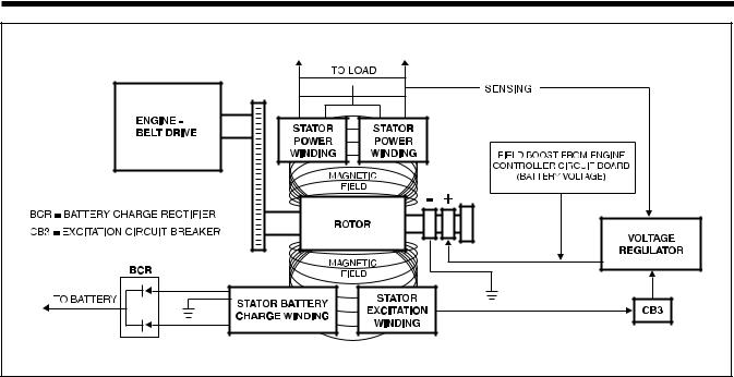
See Figure 1-1. The space surrounding a magnet is permeated by magnetic lines of force called “flux”. These lines of force are concentrated at the magnet's north and south poles. They are directed away from the magnet at its north pole, travel in a loop and reenter the magnet at its south pole. The lines of force form definite patterns which vary in intensity depending on the strength of the magnet. The lines of force never cross one another. The area surrounding a magnet in which its lines of force are effective is called a “magnetic field”.
Like poles of a magnet repel each other, while unlike poles attract each other.
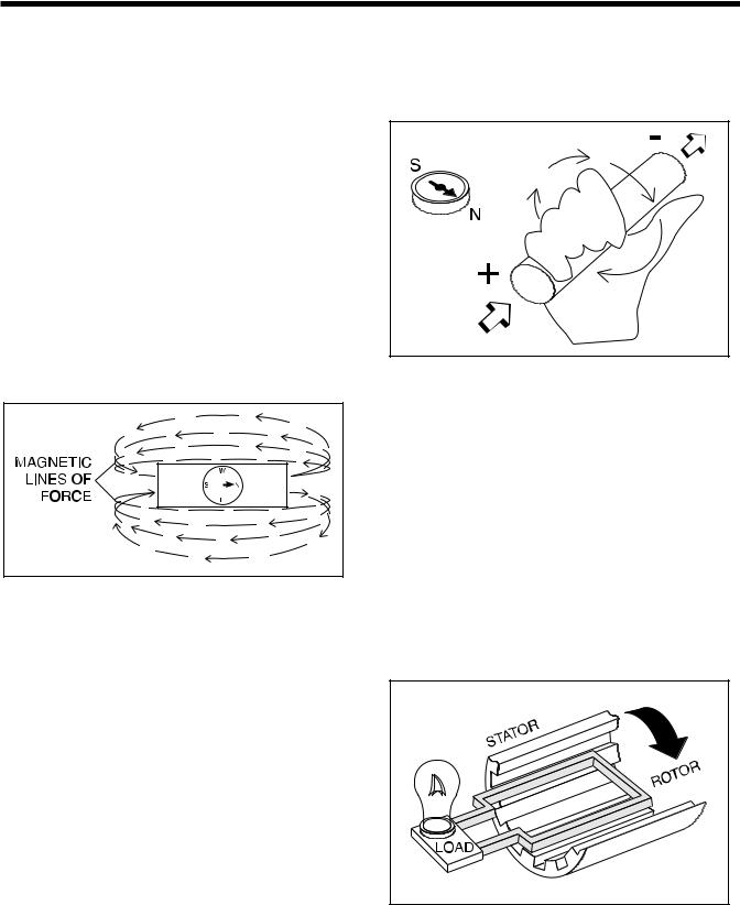
NOTE: The “right hand rule” is based on the “current flow” theory which assumes that current flows from positive to negative. This is opposite the “electron” theory, which states that current flows from negative to positive.
Figure 1-2. – The Right Hand Rule
Figure 1-1. – Magnetic Lines of Force
ELECTROMAGNETIC FIELDS
All conductors through which an electric current Is flowing have a magnetic field surrounding them. This field is always at right angles to the conductor. If a compass is placed near the conductor, the compass needle will move to a right angle with the conductor. The following rules apply:
•The greater the current flow through the conductor, the stronger the magnetic field around the conductor.
•The increase in the number of lines of force is directly proportional to the increase in current flow and the field is distributed along the full length of the conductor.
•The direction of the lines of force around a conductor can be determined by what is called the “right hand rule”. To apply this rule, place your right hand around the conductor with the thumb pointing in the direction of current flow. The fingers will then be pointing in the direction of the lines of force.
ELECTROMAGNETIC INDUCTION
An electromotive force (EMF) or voltage can be produced in a conductor by moving the conductor so that it cuts across the lines of force of a magnetic field.
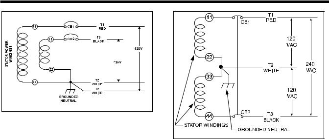
Similarly, if the magnetic lines of force are moved so that they cut across a conductor, an EMF (voltage) will be produced in the conductor. This is the basic principal of the revolving field generator.
Figure 1-3, below, illustrates a simple revolving field generator. The permanent magnet (Rotor) is rotated so that its lines of magnetic force cut across a coil of wires called a Stator. A voltage is then induced into the Stator windings. If the Stator circuit is completed by connecting a load (such as a light bulb), current will flow in the circuit and the bulb will light.
Figure 1-3. – A Simple Revolving Field Generator
Page 3

Section 1
GENERATOR FUNDAMENTALS
A SIMPLE AC GENERATOR
Figure 1-4 shows a very simple AC Generator. The generator consists of a rotating magnetic field called a ROTOR and a stationary coil of wire called a STATOR. The ROTOR is a permanent magnet which consists of a SOUTH magnetic pole and a NORTH magnetic pole.
As the MOTOR turns, its magnetic field cuts across the stationary STATOR. A voltage is induced Into the STATOR windings. When the magnet's NORTH pole passes the STATOR, current flows in one direction. Current flows in the opposite direction when the magnet's SOUTH pole passes the STATOR. This constant reversal of current flow results in an alternating current (AC) waveform that can be diagrammed as shown in Figure 1-5.
The ROTOR may be a 2-pole type having a single NORTH and a single SOUTH magnetic pole. Some ROTORS are 4-pole type with two SOUTH and two NORTH magnetic poles. The following apply:
1.The 2-pole ROTOR must be turned at 3600 rpm to produce an AC frequency of 60 Hertz, or at 3000 rpm to deliver an AC frequency of 50 Hertz.
2.The 4-pole ROTOR must operate at 1800 rpm to deliver a 60 Hertz AC frequency or at 1500 rpm to deliver a 50 Hertz AC frequency.
Figure 1-5. – Alternating Current Sine Wave
A MORE SOPHISTICATED AC GENERATOR
Figure 1-6 represents a more sophisticated generator. A regulated direct current is delivered into the ROTOR windings via carbon BRUSHES AND SLIP RINGS. This results in the creation of a regulated magnetic field around the ROTOR. As a result, a regulated voltage is induced into the STATOR. Regulated current delivered to the ROTOR is called “EXCITATION” current.
|
|
|
|
|
|
|
|
|
|
|
|
|
|
|
|
|
|
|
|
|
|
|
|
|
|
|
|
|
|
|
|
|
|
|
|
|
|
|
|
|
|
|
|
|
|
|
|
|
|
|
|
|
|
|
|
|
|
|
|
|
|
|
|
|
|
|
|
|
|
|
|
|
|
|
|
|
|
|
|
|
|
|
|
|
|
|
|
|
|
|
|
|
|
|
|
|
|
|
|
|
|
|
|
|
|
|
|
|
|
|
|
|
|
|
|
|
|
|
|
|
|
|
|
|
|
|
|
|
|
|
|
|
|
|
|
|
|
|
|
|
|
|
|
|
|
|
|
|
|
|
|
|
|
|
|
|
|
|
|
|
|
|
|
|
|
|
|
|
|
|
|
|
|
|
|
|
|
|
|
|
|
|
|
|
|
|
|
|
|
|
|
|
|
|
|
|
|
|
|
|
|
|
|
|
|
|
|
|
|
|
|
|
|
|
|
|
|
|
|
|
|
|
|
|
|
|
|
|
|
|
|
|
|
|
|
|
|
|
|
|
|
|
|
|
|
|
|
|
|
|
|
|
|
|
|
|
|
|
|
|
|
|
|
|
|
|
|
|
|
|
|
|
|
|
|
|
|
Figure 1-6. – A More Sophisticated Generator |
||||||||||
|
|
|
|
|
See Figure 1-7 (next page). The revolving magnetic |
|||||||||||
|
|
|
|
|
field (ROTOR) is driven by the engine at a constant |
|||||||||||
|
|
|
|
|
speed. This constant speed is maintained by a |
|||||||||||
|
|
|
|
|
||||||||||||
|
|
|
|
|
mechanical engine governor. Units with a 2-pole rotor |
|||||||||||
|
|
|
|
|
require an operating speed of 3600 rpm to deliver a |
|||||||||||
|
|
|
|
|
||||||||||||
Figure 1-4. – A Simple AC Generator |
60 Hertz AC output. Engine governors are set to |
|||||||||||||||
maintain approximately 3720 rpm when no electrical |
||||||||||||||||
|
|
|
|
|
||||||||||||
|
|
|
|
|
loads are connected to the generator. |
|||||||||||
Page 4
Section 1
GENERATOR FUNDAMENTALS
Figure 1-7. – Generator Operating Diagram
NOTE: AC output frequency at 3720 rpm will be about 62 Hertz. The “No-Load” is set slightly high to prevent excessive rpm, frequency and voltage droop under heavy electrical loading.
Generator operation may be described briefly as follows:
1.Some “residual” magnetism is normally present in the Rotor and is sufficient to induce approximately 7 to 12 volts AC Into
(1)If the actual (sensing) voltage is greater than the pre-set reference voltage, the Regulator will decrease the regulated current flow to the Rotor.
(2)If the actual (sensing) voltage is less than the pre-set reference voltage, the Regulator will increase the regulated current flow to the Rotor.
the STATOR's AC power windings.
2.During startup, an engine controller circuit board delivers battery voltage to the ROTOR, via the brushes and slip rings.
(3) In the manner described, the Regulator maintains an actual (sensing) voltage that is equal to the pre-set reference voltage.
NOTE: The Voltage Regulator also changes the
a.The battery voltage is called “Field Boost”. Stator excitation windings alternating current
b.Flow of direct current through the ROTOR increases the strength of the magnetic field above that of “residual” magnetism alone.
3.“Residual” plus “Field Boost” magnetism induces a voltage into the Stator excitation (DPE), battery charge and AC Power windings.
4.Excitation winding unregulated AC output is delivered to an electronic voltage regulator, via an excitation circuit breaker.
a.A “Reference” voltage has been preset into the Voltage Regulator.
b.An “Actual” (“sensing”) voltage is delivered to the Voltage Regulator via sensing leads from the Stator AC power windings.
c.The Regulator “compares” the actual (sensing) voltage to its pre-set reference voltage.
(AC) output to direct current (DC).
5.When an electrical load is connected across the Stator power windings, the circuit is completed and an electrical current will flow.
6.The Rotor's magnetic field also induces a voltage Into the Stator battery charge windings.
a.Battery charge winding AC output is delivered to a battery charge rectifier (BCR) which changes the AC to direct current (DC).
b.The rectified DC is then delivered to the unit battery, to maintain the battery in a charged state.
c.A 1 ohm, 25 watt Resistor is installed in series with the grounded side of the battery charge circuit.
Page 5

Section 1
GENERATOR FUNDAMENTALS
FIELD BOOST
When the engine is cranked during startup, the engine's starter contactor is energized closed. Battery current is then delivered to the starter motor and the engine cranks.
Closure of the starter contactor contacts also delivers battery voltage to Pin 13 of an Engine Controller circuit board. The battery current flows through a 47 ohm, 2 watt resistor and a field boost diode, then to the Rotor via brushes and slip rings. This is called “Field Boost” current.
Field boost current is delivered to the Rotor only while the engine is cranking. The effect is to “flash the field” every time the engine is cranked. Field boost current helps ensure that sufficient “pickup” voltage is available on every startup to turn the Voltage Regulator on and build AC output voltage.
NOTE: Loss of the Field Boost function may or may not result in loss of AC power winding output. If Rotor residual magnetism alone is sufficient to turn the Regulator on loss of Field Boost may go unnoticed. However, If residual magnetism alone Is not enough to turn the Regulator on, loss of the Field Boost function will result In loss of AC power winding output to the load. The AC output voltage will then drop to a value commensurate with the Rotor's residual magnetism (about 7-12 VAC).
GENERATOR AC CONNECTION SYSTEM
These air-cooled generator sets are equipped with dual stator AC power windings. These two stator windings supply electrical power to customer electrical loads by means of a dual 2-wire connection system.
You can use your generator set to supply electrical power for operating one of the following electrical loads:
•QUIETPACT 55G & LP: 120 and/or 240 volts, single phase, 60 Hz electrical loads. These loads can require up to 5500 watts (5.5 kW) of total power, but cannot exceed 45.8 AC amperes of current at 120 volts or exceed 22.9 AC amperes at 240 volts.
•QUIETPACT 65G & LP: 120 and/or 240 volts, single phase, 60 Hz electrical loads. These loads can require up to 6500 watts (6.5 kW) of total power, but cannot exceed 54.1 AC amperes of current at 120 volts or exceed 27 AC amperes at 240 volts.
•QUIETPACT 75G & LP: 120 and/or 240 volts, single phase, 60 Hz electrical loads. These loads can require up to 7500 watts (7.5 kW) of total power, but cannot exceed 62.5 AC amperes of current at 120 volts or exceed 31.2 AC amperes at 240 volts.
CAUTION! Do not overload the generator. Some installations may require that electrical loads be alternated to avoid overloading. Applying excessively high electrical loads may damage the generator and may shorten its life. Add up the rated watts of all electrical lighting, appliance, tool and motor loads the generator will power at one time. This total should not be greater than the wattage capacity of the generator. If an electrical device nameplate gives only volts and amps, multiply volts times amps to obtain watts (volts x amps = watts). Some electric motors require more watts of power (or amps of current) for starting than for continuous operation.
Generators may be installed to provide the following outputs:
1.120 VAC loads only — one load with a maximum total wattage requirement equal to the generator’s rated power output (in watts), and 120V across the generator output terminals. Figure 1.8, page 7, shows the generator lead wire connections for 120VAC ONLY.
2.120/240 VAC loads — one load with a maximum total wattage requirement equal to the generator’s rated power output, and 240V across the generator output terminals; or two separate loads, each with a maximum total wattage requirement equal to half of the generator’s rated power output (in watts), and 120V across the generator output terminals. Figure 1.9 on page 7, shows the generator lead wire connections for 120/240 VAC loads.
LINE BREAKERS (120 VOLTS ONLY):
Protects generator’s AC output circuit against overload, i.e., prevents unit from exceeding wattage/amperage capacity. The circuit breaker ratings are as follows:
|
Model |
Circuit Breaker 1 |
Circuit Breaker 2 |
|
|
QuietPact 55 |
30A |
20A |
|
|
QuietPact 65 |
30A |
30A |
|
|
QuietPact 75 |
35A |
35A |
|
|
|
|
|
|
Page 6
Section 1
GENERATOR FUNDAMENTALS
Figure 1-8. – Connection for 120 Volts Only
RECONNECTION FOR DUAL VOLTAGE OUTPUT:
When connected for dual voltage output, Stator output leads 11P and 44 form two “hot” leads (T1Red and T3Black). The junction of leads 22P and 33 form the “Neutral” line (T2White).
For dual voltage output, the “Neutral” line remains grounded.
NOTE: For units with two 30 amp or two 35 amp main breakers, the existing breakers may be reused when reconnecting for dual voltage output. However, on units with a 30 amp and a 20 amp main breaker, you may wish to install a 2-pole breaker that is rated closer to the unit’s rated capacity (use two 25 amp main breakers).
Figure 1-9 - Connection for 120/240 Volts |
NOTE: If this generator has been reconnected for dual voltage AC output (120/240 volts), the replacement line breakers should consist of two separate breakers with a connecting piece between the breaker handles (so that both breakers operate at the same time). If the unit is reconnected for dual voltage, it is no longer RVIA listed.
Page 7
Section 2
MAJOR GENERATOR COMPONENTS
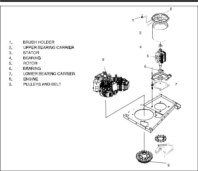
Figure 2-1. Exploded View of Generator
ROTOR ASSEMBLY |
STATOR ASSEMBLY |
The Rotor is sometimes called the “revolving field”, since it provides the magnetic field that induces a voltage into the stationary Stator windings. Slip rings on the Rotor shaft allow excitation current from the voltage regulator to be delivered to the Rotor windings. The Rotor is driven by the engine at a constant speed through a pulley and belt arrangement.
All generator models in this manual utilize a 2-pole Rotor, i.e., one having a single north and a single south pole. This type of Rotor must be driven at 3600 rpm for a 60 Hertz AC output, or at 3000 rpm for a 50 Hertz output.
Slip rings may be cleaned. If dull or tarnished, clean them with fine sandpaper (a 400 grit wet sandpaper is recommended). DO NOT USE ANY METALLIC GRIT OR ABRASIVE TO CLEAN SLIP RINGS.
The Stator is “sandwiched” between the upper and lower bearing carriers and retained in that position by four Stator studs. Windings Included in the Stator assembly are (a) dual AC power windings, (b) an excitation or DPE winding, and (c) a battery charge winding. A total of eleven (11) leads are brought out of the Stator as follows:
1.Four (4) Stator power winding output leads (Wires No. 11P, 22P, 33 and 44). These leads deliver power to connected electrical loads.
2.Stator Power winding “sensing” leads (11S and 22S). These leads deliver an “actual voltage signal to the electronic Voltage Regulator.
Page 8
Section 2
MAJOR GENERATOR COMPONENTS
3.Two excitation winding output leads (No. 2 and 6). These leads deliver unregulated excitation current to the voltage regulator.
4.Three (3) battery charge output leads (No. 55, 66 and 77).
via the rectifier, a 7.5 amp fuse and Wire No. 13. A 1 ohm, 25 watt resistor is connected in series with the grounded side of the circuit.
Figure 2-4. – Battery Charge Circuit
Figure 2-2. – Stator Output Leads
BRUSH HOLDER
The brush holder is retained in the rear bearing carrier by two M5 screws. It retains two brushes, which contact the Rotor slip rings and allow current flow from stationary parts to the revolving Rotor. The positive (+) brush is located nearest the Rotor bearing.
Figure 2-3. – Brush Holder |
BATTERY CHARGE COMPONENTS
The Stator incorporates dual battery charge windings. A battery charge rectifier (BCR) changes the AC output of these windings to direct current (DC). Battery charge winding output is delivered to the unit battery
EXCITATION CIRCUIT COMPONENTS
GENERAL:
During operation, the Rotor's magnetic field induces a voltage and current flow into the Stator excitation winding. The resultant AC output is delivered to a voltage regulator via an excitation circuit breaker (CB3).
Figure 2-5. – Schematic: Excitation Circuit
EXCITATION CIRCUIT BREAKER:
The excitation circuit breaker (CB3) is self-resetting and cannot be reset manually. Should the breaker open for any reason, excitation current flow to the
Page 9
Section 2
MAJOR GENERATOR COMPONENTS
Rotor will be lost. The unit’s AC output voltage will then drop to a value commensurate with the Rotor's residual magnetism (about 7-12 VAC).
Figure 2-6. – Excitation Circuit Breaker
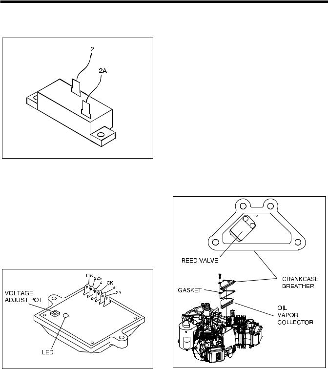
VOLTAGE REGULATOR:
Six (6) leads are connected to the voltage regulator as follows:
•Two (2) SENSING leads deliver ACTUAL AC output voltage signals to the regulator. These are Wires No. 11S and 22S.
•Two (2) leads (4 and 0K) deliver the regulated direct current to the Rotor, via brushes and slip rings.
•Two (2) leads (No. 6 and 2A) deliver Stator excitation winding AC output to the regulator.
Figure 2-7. – Voltage Regulator |
The regulator mounts a “VOLTAGE ADJUST” potentiometer, used for adjustment of the pre-set REFERENCE voltage. A lamp (LED) will turn on to indicate that SENSING voltage is available to the regulator and the regulator is turned on.
ADJUSTMENT PROCEDURE:
With the frequency set at 62.5 Hertz and no load on the generator, slowly turn the voltage adjust pot on the voltage regulator until 124 VAC is measured. If voltage is not adjustable, proceed to Section 6 - Troubleshooting; Problem 2.
NOTE: If, for any reason, sensing voltage to the regulator is lost, the regulator will shut down and excitation output to the Rotor will be lost. The AC output voltage will then drop to a value that is commensurate with Rotor residual magnetism (about 7-12 VAC). Without this automatic shutdown feature, loss of sensing (actual) voltage to the regulator would result in a “full field” or “full excitation” condition and an extremely high AC output voltage.
NOTE: Adjustment of the regulator's “VOLTAGE ADJUST” potentiometer must be done only when the unit is running at its correct governed no-load speed. Speed is correct when the unit's no-load AC output frequency is about 62.5 Hertz. At the stated frequency, AC output voltage should be about 124 volts.
CRANKCASE BREATHER
Figure 2-8. – Crankcase Breather |
DESCRIPTION:
The crankcase breather is equipped with a reed valve to control and maintain a partial vacuum in the crankcase. The breather is vented to the intake
Page 10
Section 2
MAJOR GENERATOR COMPONENTS
elbow. The breather chamber contains a removable oil vapor collector. Oil vapor is condensed on the collector material and drains back into the crankcase, which minimizes the amount of oil vapor entering the breather.
CHECK BREATHER:
1.Disconnect breather tube and remove four screws and breather. Discard gasket.
2.Check to see that reed valve is not deformed (Figure 2-8).
Note: Reed valve must form a complete seal around vent hole.
3.Remove oil vapor collector and retainer.
4.Check collector for deterioration and replace if necessary.
INSTALL BREATHER:
1. Install oil vapor collector and retainer.
Note: Push oil vapor collector and retainer in until it bottoms.
2.Install breather with new gasket (Figure 2-8). a. Torque screws to 5-8 ft-lbs.
3.Assemble breather tube to intake elbow.
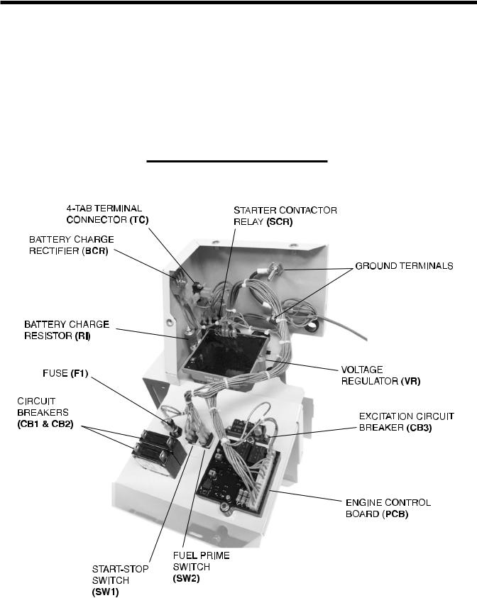
CONTROL PANEL COMPONENT IDENTIFICATION
Figure 2-9. – Control Panel Components
Page 11
Section 3
INSULATION RESISTANCE TESTS
EFFECTS OF DIRT AND MOISTURE
Moisture and dirt are detrimental to the continued good operation of any generator set.
If moisture is allowed to remain in contact with the Stator and Rotor windings, some of the moisture will be retained in voids and cracks of the winding Insulation. This will result in a reduced Insulation resistance and, eventually, the unit's AC output will be affected.
Insulation used in the generator is moisture resistant. However, prolonged exposure to moisture will gradually reduce the resistance of the winding insulation.
Dirt can make the problem worse, since it tends to hold moisture Into contact with the windings. Salt, as from sea air, contributes to the problem since salt can absorb moisture from the air. When salt and moisture combine, they make a good electrical conductor.
Because of the detrimental affects of dirt and moisture, the generator should be kept as clean and as dry as possible. Rotor and Stator windings should be tested periodically with an insulation resistance tester (such as a megohmmeter or hi-pot tester).
If the Insulation resistance is excessively low, drying may be required to remove accumulated moisture. After drying, perform a second insulation resistance test. If resistance is still low after drying, replacement of the defective Rotor or Stator may be required.
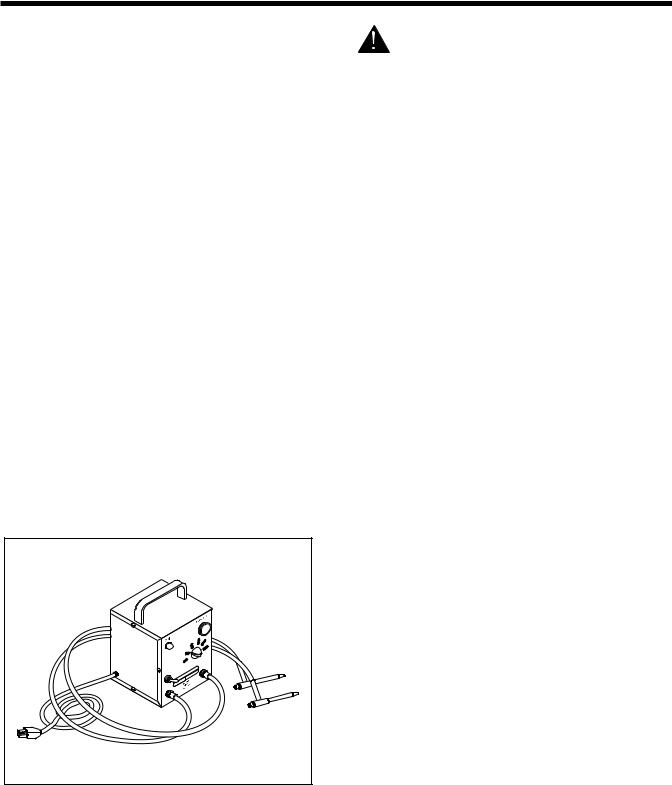
INSULATION RESISTANCE TESTERS
Figure 3-1 shows one kind of hi-pot tester. The tester shown has a “Breakdown” lamp that will glow during the test procedure to indicate an insulation breakdown in the winding being tested.
Figure 3-1. – One Type of Hi-Pot Tester
DANGER! INSULATION RESISTANCE TESTERS SUCH AS HI-POT TESTERS AND MEGOHMMETERS ARE A SOURCE OF HIGH AND DANGEROUS ELECTRICAL VOLTAGE. FOLLOW THE TESTER MANUFACTURER'S INSTRUCTIONS CAREFULLY. USE COMMON SENSE TO AVOID DANGEROUS ELECTRICAL SHOCK
DRYING THE GENERATOR
GENERAL:
If tests indicate the insulation resistance of a winding is below a safe value, the winding should be dried before operating the generator. Some recommended drying procedures Include (a) heating units and (b) forced air.
HEATING UNITS:
If drying is needed, the generator can be enclosed in a covering. Heating units can then be installed to raise the temperature about 15°-18° F. (8°-10° C.) above ambient temperature.
FORCED AIR:
Portable forced air heaters can be used to dry the generator. Direct the heated air into the generator’s air intake openings. Remove the voltage regulator and run the unit at no-load. Air temperature at the point of entry into the generator should not exceed 150° F. (66° C.).
CLEANING THE GENERATOR
GENERAL:
The generator can be cleaned properly only while it is disassembled. The cleaning method used should be determined by the type of dirt to be removed. Be sure to dry the unit after it has been cleaned.
NOTE: A shop that repairs electric motors may be able to assist you with the proper cleaning of generator windings. Such shops are often experienced In special problems such as a sea coast environment, marine or wetland applications, mining, etc.
USING SOLVENTS FOR CLEANING:
If dirt contains oil or grease a solvent is generally required. Only petroleum distillates should be used to clean electrical components. Recommended are safety type petroleum solvents having a flash point greater than 100° F. (38° C.).
Page 12

Section 3
INSULATION RESISTANCE TESTS
CAUTION!: Some generators may use epoxy or polyester base winding varnishes. Use solvents that will not attack such materials.
Use a soft brush or cloth to apply the solvent. Be careful to avoid damage to wire or winding insulation. After cleaning, dry all components thoroughly using mois- ture-free, low-pressure compressed air.
DANGER!: DO NOT ATTEMPT TO WORK WITH SOLVENTS IN ANY ENCLOSED AREA. PROVIDE ADEQUATE VENTILATION WHEN WORKING WITH SOLVENTS. WITHOUT ADEQUATE VENTILATION, FIRE, EXPLOSION OR HEALTH HAZARDS MAY EXIST . WEAR EYE PROTECTION. WEAR RUBBER GLOVES TO PROTECT THE HANDS.
CLOTH OR COMPRESSED AIR:
For small parts or when dry dirt is to be removed, a dry cloth may be satisfactory. Wipe the parts clean, then use low pressure air at 30 psi (206 Kpa) to blow dust away.
BRUSHING AND VACUUM CLEANING:
Brushing with a soft bristle brush followed by vacuum cleaning is a good method of removing dust and dirt. Use the soft brush to loosen the dirt, then remove it with the vacuum.
STATOR INSULATION RESISTANCE
GENERAL:
Insulation resistance is a measure of the Integrity of the insulating materials that separate electrical windings from the generator's steel core. This resistance can degrade over time due to the presence of contaminants, dust, dirt, grease and especially moisture).
The normal Insulation resistance for generator windings is on the order of “millions of ohms” or “megohms”.
When checking the insulation resistance, follow the tester manufacturer's Instructions carefully. Do NOT exceed the applied voltages recommended in this manual. Do NOT apply the voltage longer than one
(1) second.
CAUTION!: DO NOT connect the Hi-Pot Tester or Megohmmeter test leads to any leads that are routed into the generator control panel. Connect the tester leads to the Stator or Rotor leads only.
STATOR SHORT-TO-GROUND TESTS:
See Figure 3-2. To test the Stator for a short-to- ground condition, proceed as follows:
1.Disconnect and Isolate all Stator leads as follows:
a.Disconnect sensing leads 11S and 22S from the voltage regulator.
b.Disconnect excitation winding lead No. 6 from the voltage regulator.
c.Disconnect excitation lead No. 2 from the excitation circuit breaker (CB3).
d.Disconnect battery charge winding leads No. 66 and 77 from the battery charge rectifier (BCR).
e.Disconnect battery charge winding lead No. 55 from the battery charge resistor (R1).
f.At the main circuit breakers, disconnect AC power leads No. 11P and 33.
g.At the 4-tab ground terminal (GT), disconnect Stator power leads No. 22P and 44.
2.When all leads have been disconnected as outlined in Step 1 above, test for a short-to-ground condition as follows:
a.Connect the terminal ends of all Stator leads together (11S, 22S, 11P, 22P, 33, 44, 2,6, 55, 66, 77).
b.Follow the tester manufacturer's instructions carefully. Connect the tester leads across all Stator leads and to frame ground on the Stator can. Apply a voltage of 1500 volts. Do NOT apply voltage longer than one (1) second.
If the test Indicates a breakdown in Insulation, the Stator should be cleaned, dried and re-tested. If the winding fails the second test (after cleaning and drying), replace the Stator assembly.
TEST BETWEEN ISOLATED WINDINGS:
1.Follow the tester manufacturer's instructions carefully. Connect the tester test leads across Stator leads No. 11P and 2. Apply a voltage of 1500 voltsDO NOT EXCEED 1 SECOND.
2.Repeat Step 1 with the tester leads connected across the following Stator leads:
a.Across Wires No. 33 and 2.
b.Across Wires No. 11P and 66.
c.Across Wires No. 33 and 66.
d.Across Wires No. 2 and 66.
If a breakdown in the insulation between isolated windings is indicated, clean and dry the Stator. Then, repeat the test. If the Stator fails the second test, replace the Stator assembly.
Page 13
Section 3
INSULATION RESISTANCE TESTS
TEST BETWEEN PARALLEL WINDINGS:
Connect the tester leads across Stator leads No. 11P and 33. Apply a voltage of 1500 volts. If an insulation breakdown is indicated, clean and dry the Stator. Then, repeat the test between parallel windings. If the Stator fails the second test, replace it.
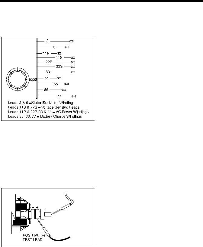
Figure 3-2. – Stator Leads
TESTING ROTOR INSULATION
To test the Rotor for insulation breakdown, proceed as follows:
1.Disconnect wires from the Rotor brushes or remove the brush holders with brushes.
2.Connect the tester positive (+) test lead to the positive (+) slip ring (nearest the Rotor bearing). Connect the tester negative (-) test lead to a clean frame ground (like the Rotor shaft).
Figure 3-3. – Rotor Test Points
3.Apply 1000 volts. DO NOT APPLY VOLTAGE LONGER THAN 1 SECOND.
If an insulation breakdown is indicated, clean and dry the Rotor then repeat the test. Replace the Rotor if it fails the second test (after cleaning and drying).
THE MEGOHMMETER
GENERAL:
A megohmmeter, often called a “megger”, consists of a meter calibrated in megohms and a power supply. Use a power supply of 1500 volts when testing Stators; or 1000 volts when testing the Rotor. DO NOT APPLY VOLTAGE LONGER THAN ONE (1) SECOND.
TESTING STATOR INSULATION:
All parts that might be damaged by the high megger voltages must be disconnected before testing. Isolate all Stator leads (Figure 3-2) and connect all of the Stator leads together. FOLLOW THE MEGGER MANUFACTURER'S INSTRUCTIONS CAREFULLY.
Use a megger power setting of 1500 volts. Connect one megger test lead to the junction of all Stator leads, the other test lead to frame ground on the Stator can. Read the number of megohms on the meter.
MINIMUM INSULATION |
|
GENERATOR RATED VOLTS |
|
|
RESISTANCE |
= |
__________________________ |
+1 |
|
1000 |
||||
(in “Megohms”) |
|
|
||
|
|
|
The MINIMUM acceptable megger reading for Stators may be calculated using the following formula:
EXAMPLE: Generator is rated at 120 volts AC. Divide “120” by “1000” to obtain “0.12”. Then add “1” to obtain “1.12” megohms. Minimum Insulation resistance for a 120 VAC Stator Is 1.12 megohms.
If the Stator insulation resistance is less than the calculated minimum resistance, clean and dry the Stator. Then, repeat the test. If resistance is still low, replace the Stator.
Use the Megger to test for shorts between isolated windings as outlined “Stator Insulation Resistance”.
Also test between parallel windings. See “Test Between Parallel Windings”on this page.
TESTING ROTOR INSULATION:
Apply a voltage of 1000 volts across the Rotor positive (+) slip ring (nearest the rotor bearing), and a clean frame ground (i.e. the Rotor Shaft). DO NOT EXCEED 1000 VOLTS AND DO NOT APPLY VOLTAGE LONGER THAN 1 SECOND. FOLLOW THE MEGGER MANUFACTURER'S INSTRUCTIONS CAREFULLY.
ROTOR MINIMUM INSULATION RESISTANCE:
1.5 megohms
Page 14
Section 4
MEASURING ELECTRICITY
METERS
Devices used to measure electrical properties are called meters. Meters are available that allow one to measure (a) AC voltage, (b) DC voltage, (c) AC frequency, and (d) resistance In ohms. The following apply:
To measure AC voltage, use an AC voltmeter.
To measure DC voltage, use a DC voltmeter.
Use a frequency meter to measure AC frequency In “Hertz” or “cycles per second”..
Use an ohmmeter to read circuit resistance, in “ohms”.
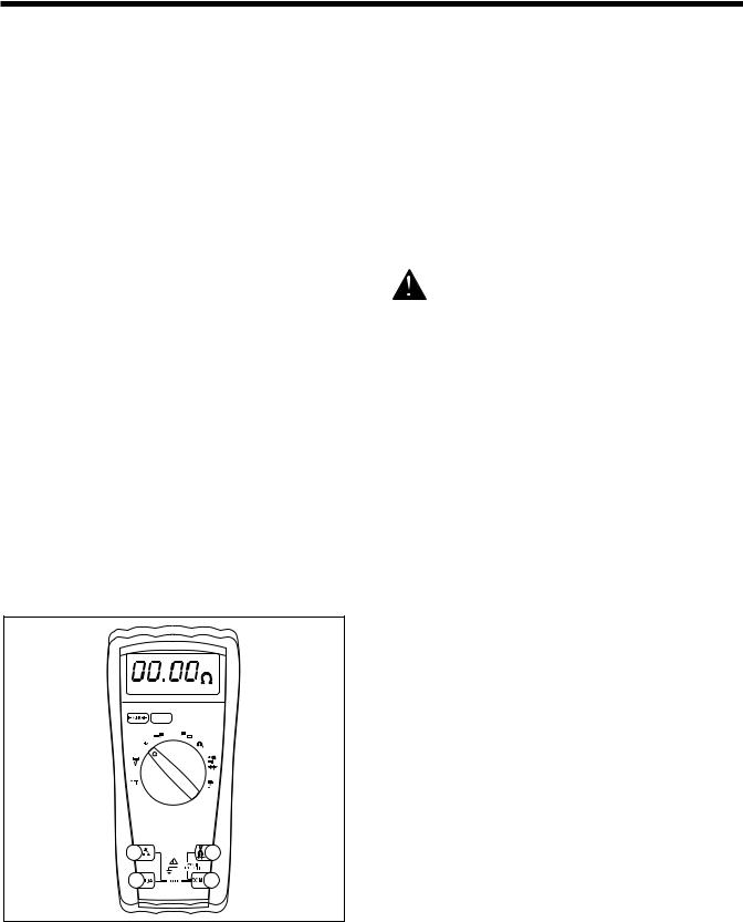
THE VOM
A meter that will permit both voltage and resistance to be read is the “volt-ohm-milliammeter” or “VOM”.
Some VOM's are of the “analog” type (not shown). These meters display the value being measured by physically deflecting a needle across a graduated scale. The scale used must be Interpreted by the user.
“Digital” VOM's (Figure 4-1) are also available and are generally very accurate. Digital meters display the measured values directly by converting the values to numbers.
NOTE: Standard AC voltmeters react to the AVERAGE value of alternating current. When working with AC, the effective value is used. For that reason a different scale is used on an AC voltmeter. The scale is marked with the effective or “rms” value even though the meter actually reacts to the average value. That is why the AC voltmeter will give an Incorrect reading if used to measure direct current (DC).
Figure 4-1. – Digital VOM
MEASURING AC VOLTAGE
An accurate AC voltmeter or a VOM may be used to read the generator's AC output voltage. The following apply:
1.Always read the generator's AC output voltage only at the unit's rated operating speed and AC frequency.
2.The generator's voltage regulator can be adjusted for correct output voltage only while the unit is operating at its correct rated speed and frequency.
3.Only an AC voltmeter may be used to measure AC voltage. DO NOT USE A DC VOLTMETER FOR THIS PURPOSE.
DANGER!: RV GENERATORS PRODUCE HIGH AND DANGEROUS VOLTAGES. CONTACT WITH HIGH VOLTAGE TERMINALS WILL RESULT IN DANGEROUS AND POSSIBLY LETHAL ELECTRICAL SHOCK.
MEASURING DC VOLTAGE
A DC voltmeter or a VOM may be used to measure DC voltages. Always observe the following rules:
1.Always observe correct DC polarity.
a.Some VOM's may be equipped with a polarity switch.
b.On meters that do not have a polarity switch, DC polarity must be reversed by reversing the test leads.
2.Before reading a DC voltage, always set the meter to a higher voltage scale than the anticipated reading. if in doubt, start at the highest scale and adjust the scale downward until correct readings are obtained.
3.The design of some meters is based on the “current flow” theory while others are based on the “electron flow” theory.
a.The “current flow” theory assumes that direct current flows from the positive (+) to the negative (-).
b.The “electron flow” theory assumes that current flows from negative (-) to positive
(+).
NOTE: When testing generators, the “current flow” theory is applied. That is, current is assumed to flow from positive (+) to negative (-).
Page 15
Section 4
MEASURING ELECTRICITY
MEASURING AC FREQUENCY
The generator's AC output frequency is proportional to Rotor speed. Generators equipped with a 2-pole Rotor must operate at 3600 rpm to supply a frequency of 60 Hertz. Units with 4-pole Rotor must run at 1800 rpm to deliver 60 Hertz.
Correct engine and Rotor speed is maintained by an engine speed governor. For models rated 60 Hertz, the governor is generally set to maintain a no-load frequency of about 62 Hertz with a corresponding output voltage of about 124 volts AC line-to-neutral. Engine speed and frequency at no-load are set slightly high to prevent excessive rpm and frequency droop under heavy electrical loading.
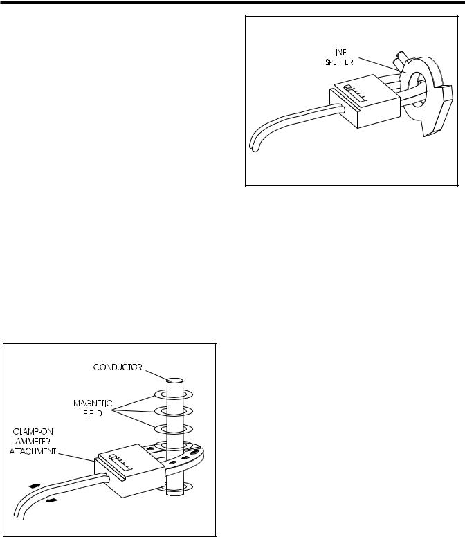
MEASURING CURRENT
To read the current flow, in AMPERES, a clamp-on ammeter may be used. This type of meter indicates current flow through a conductor by measuring the strength of the magnetic field around that conductor. The meter consists essentially of a current transformer with a split core and a rectifier type instrument connected to the secondary. The primary of the current transformer is the conductor through which the current to be measured flows. The split core allows the Instrument to be clamped around the conductor without disconnecting it.
Current flowing through a conductor may be measured safely and easily. A line-splitter can be used to measure current in a cord without separating the conductors.
Figure 4-2. – Clamp-On Ammeter |
Figure 4-3. – A Line-Splitter
NOTE: If the physical size of the conductor or ammeter capacity does not permit all lines to be measured simultaneously, measure current flow in each individual line. Then, add the Individual readings.
MEASURING RESISTANCE
The volt-ohm-milliammeter may be used to measure the resistance in a circuit. Resistance values can be very valuable when testing coils or windings, such as the Stator and Rotor windings.
When testing Stator windings, keep in mind that the resistance of these windings is very low. Some meters are not capable of reading such a low resistance and will simply read “continuity”.
If proper procedures are used, the following conditions can be detected using a VOM:
A “short-to-ground” condition in any Stator or Rotor winding.
Shorting together of any two parallel Stator windings.
Shorting together of any two isolated Stator windings.
An open condition in any Stator or Rotor winding.
Component testing may require a specific resistance value or a test for “infinity” or “continuity.” Infinity is an OPEN condition between two electrical points, which would read as no resistance on a VOM. Continuity is a closed condition between two electrical points, which would be indicated as very low resistance or “ZERO” on a VOM.
Page 16
Section 4
MEASURING ELECTRICITY
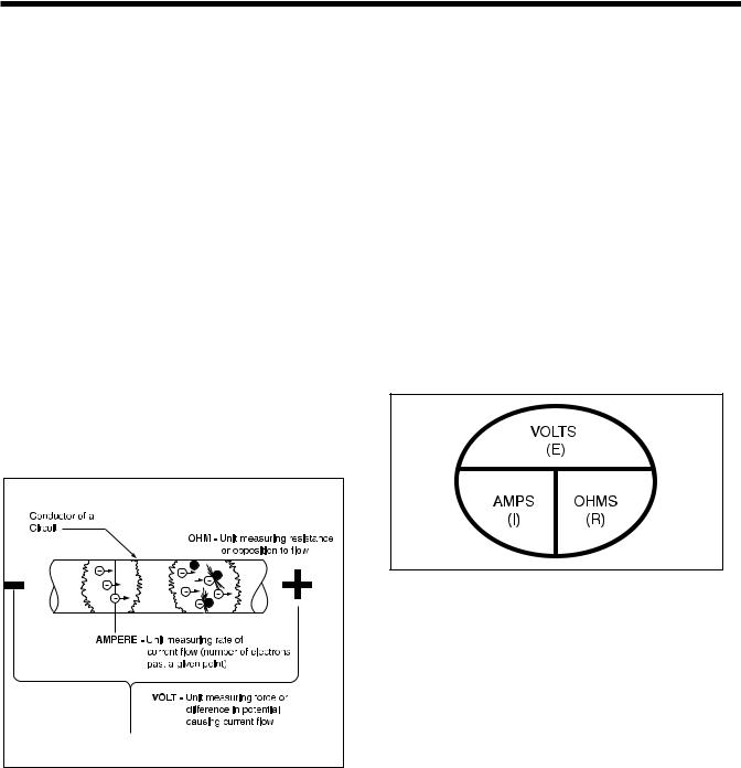
ELECTRICAL UNITS
AMPERE:
The rate of electron flow in a circuit is represented by the AMPERE. The ampere is the number of electrons flowing past a given point at a given time. One AMPERE is equal to just slightly more than six thousand million billion electrons per second.
With alternating current (AC), the electrons flow first in one direction, then reverse and move in the opposite direction. They will repeat this cycle at regular intervals. A wave diagram, called a “sine wave” shows that current goes from zero to maximum positive value, then reverses and goes from zero to maximum negative value. Two reversals of current flow is called a cycle. The number of cycles per second is called frequency and is usually stated in “Hertz”.
VOLT:
The VOLT is the unit used to measure electrical PRESSURE, or the difference in electrical potential that causes electrons to flow. Very few electrons will flow when voltage is weak. More electrons will flow as voltage becomes stronger. VOLTAGE may be considered to be a state of unbalance and current flow as an attempt to regain balance. One volt is the amount of EMF that will cause a current of 1 ampere to flow through 1 ohm of resistance.
Figure 4-4. – Electrical Units |
OHM:
The OHM is the unit of RESISTANCE. In every circuit there is a natural resistance or opposition to the flow of electrons. When an EMF is applied to a complete circuit, the electrons are forced to flow in a single direction rather than their free or orbiting pattern. The resistance of a conductor depends on (a) its physical makeup, (b) its cross-sectional area, (c) its length, and (d) its temperature. As the conductor's temperature increases, its resistance increases in direct proportion. One (1) ohm of resistance will permit one (1) ampere of current to flow when one (1) volt of electromotive force (EMF) is applied.
OHM'S LAW
A definite and exact relationship exists between VOLTS, OHMS and AMPERES. The value of one can be calculated when the value of the other two are known. Ohm's Law states that in any circuit the current will increase when voltage increases but resistance remains the same, and current will decrease when resistance Increases and voltage remains the same.
Figure 4-5.
If AMPERES is unknown while VOLTS and OHMS are known, use the following formula:
AMPERES = VOLTSOHMS
If VOLTS is unknown while AMPERES and OHMS are known, use the following formula:
VOLTS = AMPERES x OHMS
If OHMS is unknown but VOLTS and AMPERES are known, use the following:
OHMS = |
VOLTS |
|
AMPERES |
||
|
Page 17
Section 5
ENGINE DC CONTROL SYSTEM
INTRODUCTION
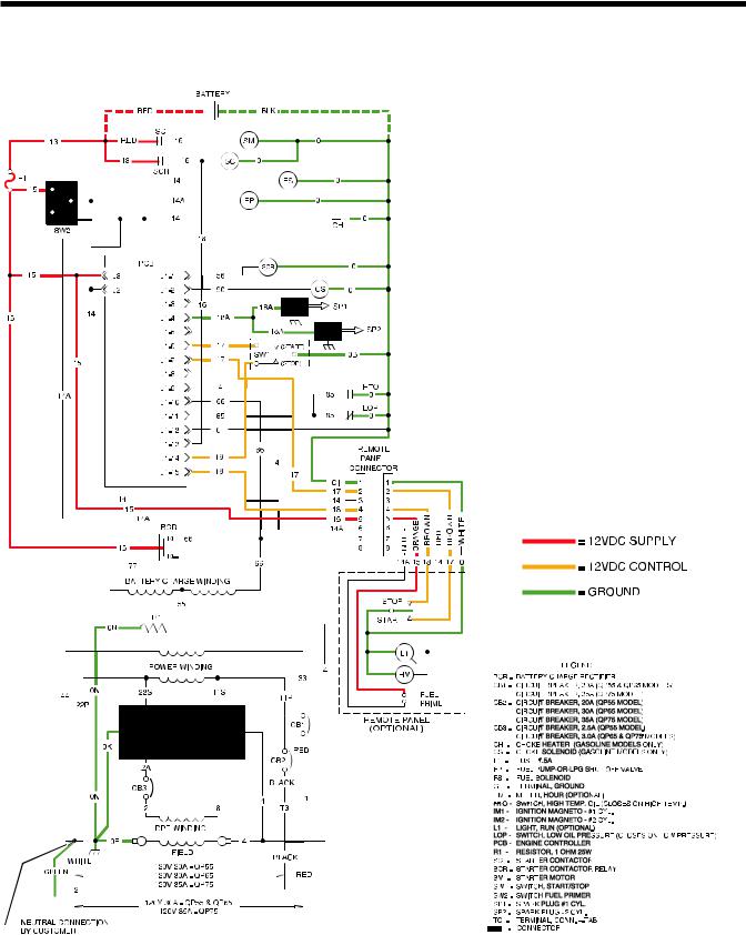
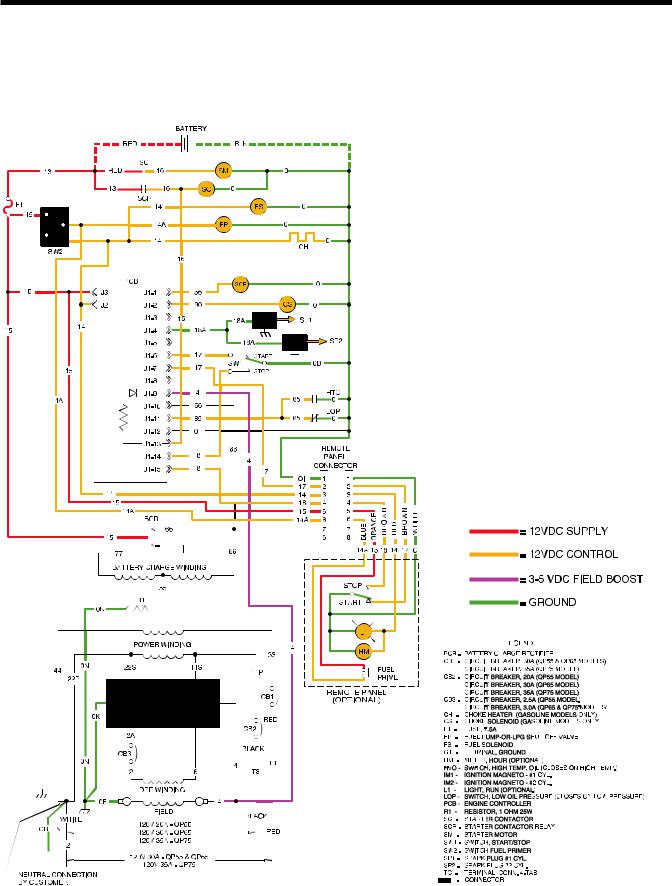
The engine DC control system includes all components necessary for the operation of the engine. Operation includes rest, priming, cranking, starting, running and shutdown. The system is shown schematically.
OPERATIONAL ANALYSIS
CIRCUIT CONDITIONREST:
Battery voltage is available to the engine controller circuit board (PCB) from the unit BATTERY and via (a) the RED battery cable, Wire 13, a 7.5 amp FUSE (F1), Wire 15 and circuit board Terminal J3. However, circuit board action is holding the circuit open and no action can occur.
Battery output is available to the contacts of a
STARTER CONTACTOR (SC) and STARTER CON-
TACTOR RELAY (SCR), but the contacts are open.
Battery voltage is also delivered to the FUEL PRIMER SWITCH (SW2). The switch is open and the circuit is incomplete.
Battery voltage is also available to the REMOTE FUEL PRIMER SWITCH. The switch is open and the circuit is incomplete.
Page 18
Section 5
ENGINE DC CONTROL SYSTEM
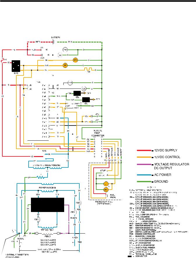
CIRCUIT CONDITIONPRIMING:
When the FUEL PRIMER SWITCH (SW2) or the REMOTE PANEL FUEL PRIMER is closed by the operator, battery voltage is delivered across the closed switch contacts and to the FUEL PUMP (FP) via Wire 14A. The FUEL SOLENOID (FS) will be energized via Wire 14 during cranking and running.
Page 19
Section 5
ENGINE DC CONTROL SYSTEM
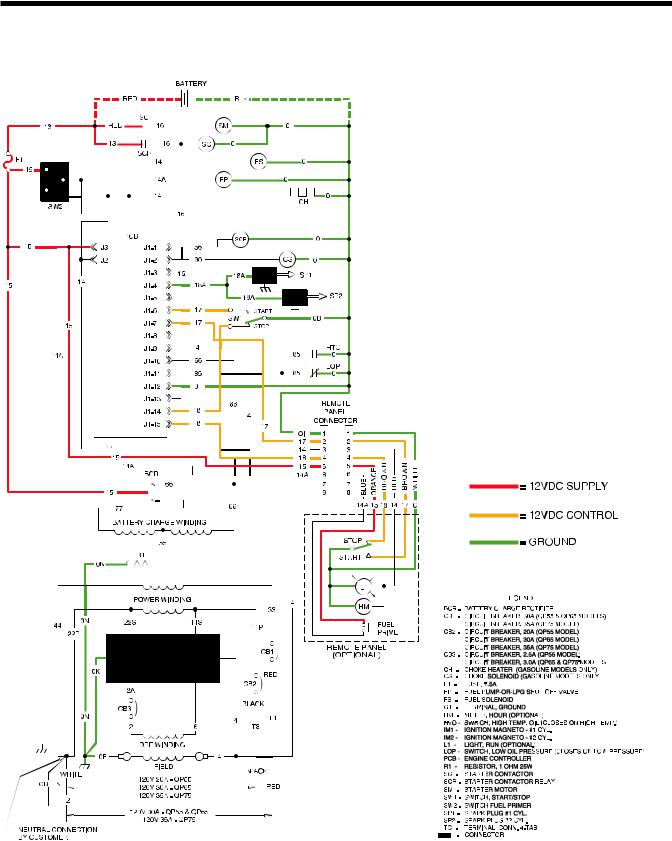
CIRCUIT CONDITIONCRANKING:
When the START-STOP-SWITCH (SW1)or REMOTE PANEL START SWITCH is held at “START” position, Wire 17 from the Engine controller circuit board is connected to frame Ground. Circuit board action will then deliver battery voltage to a STARTER CONTACTOR RELAY (SCR) via wire 56, and to a automatic CHOKE SOLENOID (CS) via Wire 90.
When battery voltage energizes the STARTER CONTACTOR RELAY (SCR), Its contacts close and battery output is delivered to the STARTER CONTACTOR (SC) via Wire 16. The STARTER CONTACTOR (SC) energizes and its contacts close, battery output is delivered to the STARTER MOTOR (SM) via Wire 16.The STARTER MOTOR energizes and the engine cranks.
When the STARTER CONTACTOR RELAY (SCR) closes, Battery voltage is also delivered to the circuit board pin location J1-13 via Wire 16. This voltage is reduced and used for field boost and is outputted from pin location J1-9.
While cranking, the CHOKE SOLENOID (CS) is energized cyclically by circuit board action (two seconds on, two seconds off).
Also while cranking, circuit board action energizes CIRCUIT BOARD TERMINAL J2 and delivers battery voltage to the Wire 14/14A circuit. This energizes the FUEL PUMP (FP) ,FUEL SOLENOID (FS) and CHOKE HEATER (CH) and optional light or hourmeter in remote panel.
Circuit board action holds open Wire 18A to common ground. The Magneto will induce a spark during cranking.
Page 20
Section 5
ENGINE DC CONTROL SYSTEM
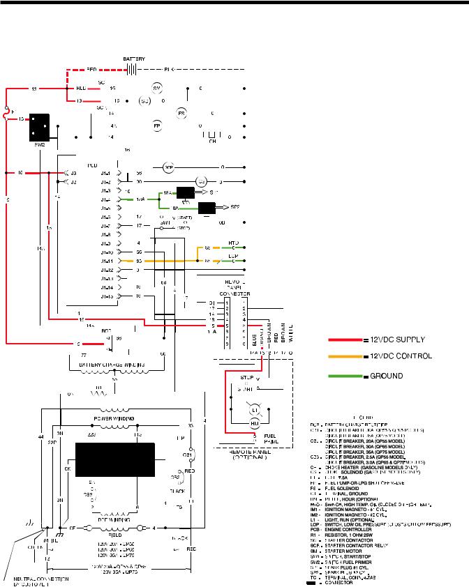
CIRCUIT CONDITION-RUNNING:
With the FUEL PUMP (FP) and FUEL SOLENOID (FS) operating and ignition occurring, the engine should start, and the START-STOP SWITCH (SW1) is released.
A voltage is induced into the Stator's BATTERY CHARGE WINDING. This voltage is delivered to the ENGINE CONTROLLER BOARD (PCB) via Wire 66 to prevent STARTER MOTOR engagement above a certain rpm.
Circuit board action terminates DC output to the STARTER CONTACTOR RELAY (SCR), which then de-energizes to end cranking. Circuit board action terminates DC output to the CHOKE SOLENOID (CS). The choke will go to a position determined by the CHOKE HEATER (CH).
The LOW OIL PRESSURE SWITCH (LOP) is normally closed. After start-up, engine oil pressure will open the LOP.
Page 21
Section 5
ENGINE DC CONTROL SYSTEM
CIRCUIT CONDITIONSHUTDOWN:
Setting the START-STOP SWITCH (SW1) or the REMOTE PANEL START-STOP SWITCH to its “STOP” position connects the Wire 18 circuit to frame ground. Circuit board action then closes the circuit to Wire 18A, grounding the ignition magneto. Circuit board action de-energizes DC output to Terminal J2. The FUEL PUMP (FP), FUEL SOLENOID (FS) and CHOKE HEATER (CH) are de-energized by the loss of DC to Wire 14. Ignition and fuel flow terminate and the engine shuts down.
Page 22
Section 5
ENGINE DC CONTROL SYSTEM
CIRCUIT CONDITIONFAULT SHUTDOWN:
The engine mounts a HIGH OIL TEMPERATURE SWITCH (HTO) and a LOW OIL PRESSURE SWITCH (LOP).
Should engine oil temperature exceed a preset value, the switch contacts will close. Wire 85 from the circuit board will connect to frame ground. Circuit board action will then initiate a shutdown.
Should engine oil pressure drop below a safe pre-set value, the switch contacts will close. On contact closure, Wire 85 will be connected to frame ground and circuit board action will initiate an engine shutdown.
The circuit board has a time delay built into it for the Wire 85 fault shutdowns. At STARTUP ONLY the circuit board will wait approximately 6 seconds before looking at the Wire 85 fault shutdowns. Once running after the 6 second time delay, grounding Wire 85 thru either switch will cause an immediate shutdown.
Page 23
Section 5
ENGINE DC CONTROL SYSTEM
ENGINE CONTROLLER CIRCUIT BOARD
a.To operate the electric Fuel Pump (FP).
b.To energize the Fuel Solenoid.
GENERAL:
The engine controller board is responsible for cranking, startup, running and shutdown operations. The board interconnects with other components of the DC control system to turn them on and off at the proper times. It is powered by fused 12 VDC power from the unit battery.
CIRCUIT BOARD CONNECTIONS:
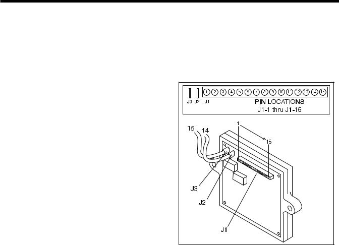
The circuit board mounts a 15-pin receptacle (J1) and two single pin terminals (J2 and J3, see Figure 5.3). Figure 5-2 shows the 15-pin receptacle (J1), the associated wires and the function(s) of each pin and wire.
PIN |
WIRE |
FUNCTION |
1 |
56 |
Delivers 12 VDC to Starter Contactor (SC) |
|
|
while cranking only. |
2 |
90 |
Delivers 12 VDC to Choke Solenoid coil |
|
|
while cranking only. (Two seconds ON, Two |
|
|
seconds OFF) |
3 |
— |
Not used. |
4 |
18A |
Grounds Magneto for Shutdown. |
5 |
— |
Not used. |
6 |
17 |
To Start-Stop switch. When wire is grounded |
|
|
by setting Start-Stop switch to “START”, |
|
|
engine will crank. |
7 |
17 |
To Start-Stop switch on optional Remote |
|
|
Panel. |
8 |
— |
Not used. |
9 |
4 |
Field Boost DC to Voltage Regulator and to |
|
|
Rotor windings. |
10 |
66 |
Starter Lockout. Prevents cranking while |
|
|
engine is running. |
11 |
85 |
Fault shutdown circuit. When grounded by clo- |
|
|
sure of High Oil Temperature or Low Oil |
|
|
Pressure Switch engine will shut down. |
12 |
0 |
Common Ground. |
13 |
16 |
12 VDC Input to Field Boost circuit while |
|
|
cranking only. |
14 |
18 |
To Start-Stop switch. When grounded by set- |
|
|
ting Switch to “STOP” engine shuts down. |
15 |
18 |
To Start-Stop Switch on optional Remote Panel. |
|
|
|
c.To operate the Choke Heater.
d.To the Remote Wire Harness to operate an hourmeter or a light.
2.Wire 15 connects to Terminal J3. This is the power supply (12 VDC) for the circuit board and the DC control system.
Figure 5-3. – Engine Controller Circuit Board
BATTERY
RECOMMENDED BATTERY:
When anticipated ambient temperatures will be consistently above 32° F. (0° C.), use a 12 volts automotive type storage battery rated 70 amp-hours and capable of delivering at least 400 cold cranking amperes.
If ambient temperatures will be below 32° (0° C.), use a 12 volt battery rated 95 amp-hours and having a cold cranking capacity of 400 amperes.
Figure 5-2. – Receptacle J1
In addition to the 15-pin receptacle (J1), the circuit board is equipped with two single pin terminals (J2 and J3). These terminals may be identified as follows:
1.Wire 14 connects to Terminal J2. During cranking and running, the circuit board delivers battery voltage to the Wire 14 circuit for the following functions:
BATTERY CABLES:
Use of battery cables that are too long or too small in diameter will result in excessive voltage drop. For best cold weather starting, voltage drop between the battery and starter should not exceed 0.12 volt per 100 amperes of cranking current.
Select the battery cables based on total cable length and prevailing ambient temperature. Generally, the longer the cable and the colder the weather, the larger the required cable diameter.
Page 24
Section 5
ENGINE DC CONTROL SYSTEM
The following chart applies:
CABLE LENGTH (IN FEET) |
RECOMMENDED CABLE SIZE |
0-10 |
No. 2 |
11-15 |
No. 0 |
16-20 |
No. 000 |
|
|
EFFECTS OF TEMPERATURE:
Battery efficiency is greatly reduced by a decreased electrolyte temperature. Such low temperatures have a decided numbing effect on the electrochemical action. Under high discharge rates (such as cranking), battery voltage will drop to much lower values in cold temperatures than in warmer temperatures. The freezing point of battery electrolyte fluid is affected by the state of charge of the electrolyte as indicated below:
SPECIFIC GRAVITY |
FREEZING POINT |
1.220 |
-35° F. (-37° C.) |
1.200 |
--20° F. (-29° C.) |
1.160 |
0° F. (-18° C.) |
|
|
ADDING WATER:
Water is lost from a battery as a result of charging and discharging and must be replaced. If the water is not replaced and the plates become exposed, they may become permanently sulfated. In addition, the plates cannot take full part in the battery action unless they are completely immersed in electrolyte. Add only DISTILLED WATER to the battery. DO NOT USE TAP WATER.
NOTE: Water cannot be added to some “mainte- nance-free” batteries.
CHECKING BATTERY STATE OF CHARGE:
Use an automotive type battery hydrometer to test the battery state of charge. Follow the hydrometer manufacturer's instructions carefully. Generally, a battery may be considered fully charged when the specific gravity of its electrolyte is 1.260. If the hydrometer used does not have a “Percentage of Charge” scale, compare the readings obtained with the following:
SPECIFIC GRAVITY |
PERCENTAGE OF CHARGE |
1.260 |
100% |
1.230 |
75% |
1.200 |
50% |
1.170 |
25% |
|
|
CHARGING A BATTERY:
Use an automotive type battery charger to recharge a battery. Battery fluid is an extremely corrosive, sulfuric acid solution that can cause severe burns. For that reason, the following precautions must be observed:
The area in which the battery is being charged must be well ventilated. When charging a battery, an explosive gas mixture forms in each cell.
Do not smoke or break a live circuit near the top of the battery. Sparking could cause an explosion.
Avoid spillage of battery fluid. If spillage occurs, flush the affected area with clear water immediately.
Wear eye protection when handling a battery.
7.5 AMP FUSE |
|
This panel-mounted Fuse |
|
protects the DC control |
|
circuit against overload |
|
and possible damage. If |
|
the Fuse has melted open |
|
due to an overload, nei- |
|
ther the priming function |
|
nor the cranking function |
|
will be available. |
Figure5-4 |
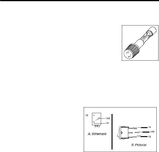
FUEL PRIMER SWITCH
Following generator installation and after the unit has been idle for some time, the fuel supply line may be empty. This condition will require a long cranking period before fuel can reach the carburetor. The Fuel Primer Switch, when actuated to its “PRIME” position will deliver battery voltage across the closed switch contacts to the Fuel Pump (FP) to turn the Pump on. Pump action will then draw fuel from the supply tank to prime the fuel lines and carburetor.
Figure 5-5. – Primer Switch
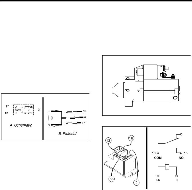
START-STOP SWITCH
The Start-Stop Switch allows the operator to control cranking, startup and shutdown. The following wires connect to the Start-Stop Switch:
1.Wire No. 17 from the Engine Controller circuit board. This Is the CRANK and START circuit. When the Switch is set to 'START”, Wire 17 is connected to frame ground via Wire OB.
a.With wire 17 grounded, a Crank Relay on the circuit board energizes and battery volt-
Page 25
Section 5
ENGINE DC CONTROL SYSTEM
age is delivered to the Starter Contactor Relay via Wire 56.The Starter Contactor Relay energizes, its contacts close and the Starter Contactor is energized via wire 16. Its contacts close and the engine cranks.
b.With Wire 17 grounded, a Run Relay on the circuit board energizes and battery voltage is delivered to the Wire 14 circuit. Battery voltage is delivered to the Fuel Pump, Fuel Solenoid, Choke Heater and the Remote Harness.
2.Wire 18 from the Engine Controller board. This Is the ENGINE STOP circuit. When the Start-Stop Switch is set to “STOP”, Wire 18 is connected to frame ground via Wire No. 0B. Circuit board action then opens the circuit to Wire 14, and grounds Wire 18A. Fuel flow to the carburetor and ignition are terminated.
3.Wire 0B connects the Switch to frame ground.
Wire 16 will supply battery power to the starter contactor and to the engine controller board for field flash when the starter contactor relay is energized. Attached to the starter contactor relay coil is wire 56 (positive supply during cranking) and wire 0 (ground).
When the Start-Stop switch is set to “START”, the circuit board delivers battery voltage to the Starter Contactor Relay via Wire 56.The Starter Contactor Relay energizes, its contacts close and the Starter Contactor is energized via wire 16. Its contacts close and battery voltage is available to the starter motor, and the engine cranks.
Figure 5-7. – Starter Motor |
Figure 5-6. – Start-Stop Switch
STARTER CONTACTOR RELAY |
|
& STARTER MOTOR |
|
The positive (+) battery cable attaches to the large lug |
|
on the STARTER CONTACTOR. Wire 13 then |
|
attaches to one side of the STARTER CONTACTOR |
|
RELAY contact, from this point Wire 13 attaches to |
|
the fuse F1 to supply battery voltage to the DC con- |
|
trol system. The opposite side of the starter contactor |
|
relay contact is connected to Wire 16. |
Figure 5-8. – Starter Contactor Relay |
|
Page 26
 Loading...