


7000EXL
Portable Generator Owner’s Manual
Problems? |
unit |
||||||
Questions? |
|||||||
|
|
|
|
|
your |
||
|
taking |
|
store, |
||||
Before |
|
the |
|
|
|||
to |
|
generator |
|||||
back |
|
|
|
|
|
at |
|
|
the |
|
|
|
1408 |
||
call |
|
|
|
|
|
||
|
|
helpline - |
|||||
|
|
|
|
270 |
|||
|
|
|
- |
|
|
5CT |
|
|
800 |
|
|
||||
- |
|
|
|
|
- |
||
1 |
|
|
F8 |
|
|||
|
|
- |
|
|
|
||
|
M |
|
|
|
|
|
|
Model No. 1470-0 (7,000 Watt AC Generator) Manual No. 186744 Revision 0 (06/13/2001)
Visit our Generac website: www.generac-portables.com
This is the safety alert symbol. It is used to alert you to potential personal injury hazards.
Obey all safety messages that follow this symbol to avoid possible injury or death.
Generac Portable Products 7000EXL Extended Life Generator
EQUIPMENT
DESCRIPTION
This generator is an engine–driven, revolving field, alternating current (AC) generator. It was designed to supply electrical power for operating compatible electrical lighting, appliances, tools and motor loads.This manual contains information for a generator that operates
120 and/or 240 Volt, single phase, 60 Hz devices that require up to 7,000 watts (7.0 kW) of power that pull up to 58.3 Amps at 120 Volts or 29.2 Amps at 240 Volts.
CAUTION! Do Not exceed the generator’s wattage/amperage capacity.Add up the rated watts of all devices you are connecting to generator receptacles at one time.This total should not be greater than 7,000 watts. See “Don’t Overload the Generator” on page 11.
The generator’s revolving field is driven at about 3600 rpm by a single-cylinder engine.
Every effort has been made to ensure that information in this manual is accurate and current. However, Generac reserves the right to change, alter or otherwise improve the product and this document at any time without prior notice.
 CAUTION! Do Not tamper with engine governed speed. High operating speeds are dangerous and increase risk of personal injury or damage to equipment.The generator supplies correct rated frequency and voltage only when running at proper governed speed. Incorrect frequency and/or voltage can damage some connected electrical loads. Operating at excessively low speeds imposes a heavy load.When adequate engine power is not available engine life may be shortened.
SAFETY RULES
This generator set was designed and manufactured for specific applications. Do Not attempt to modify the unit or use it for any application it was not designed for. If you have any questions about your generator’s application, ask your dealer or consult the factory.
The manufacturer could not possibly anticipate every circumstance that might involve a hazard. For that reason warnings in the manual and warnings on tags or decals affixed to the unit are not all–inclusive. If you intend to handle, operate or service the unit by a procedure or method not specifically recommended by the manufacturer, first make sure that such a procedure or method will not render this equipment unsafe or pose a threat to you and others.
Read this manual carefully and become familiar with your generator set. Know its applications, its limitations and any hazards involved.
WARNING:
The engine exhaust from this product contains chemicals known to the State of California to cause cancer, birth defects, or other reproductive harm.
 DANGER! You must isolate the generator from the electric utility using approved transfer equipment if this unit is used for backup power.
Failure to isolate the generator from the power utility may result in injury or death to electric utility workers and damage to the generator due to a backfeed of electrical energy. Whenever unit is providing backup power, the electric utility must be notified.
DANGER! Generator exhaust gases contain DEADLY carbon monoxide gas. If breathed in sufficient concentrations, carbon monoxide can cause unconsciousness or death. Operate this equipment outdoors where adequate ventilation is available.
The Emission Control System for this generator is warranted for standards set by the Environmental Protection Agency. For warranty information refer to the engine owner’s manual.
2
Generac Portable Products 7000EXL Extended Life Generator
•The generator produces a very powerful voltage that can cause serious injury or death by electrocution. Never touch bare wires or receptacles. Never permit a child or any unqualified person to operate the generator.
•Never handle any kind of electrical cord or device while standing in water, while barefoot or while hands or feet are wet. Death or serious injury from electrocution may result.
•Use a ground fault circuit interrupter (GFCI) in any damp or highly conductive area (such as metal decking or steel work).
•Never use worn, bare, frayed or otherwise damaged electrical cords with the generator. Death, serious injury and property damage from electrical shock may result.
•Gasoline is highly FLAMMABLE and its vapors are EXPLOSIVE. Never allow smoking, open flames, sparks or heat in the vicinity while handling gasoline. Avoid spilling gasoline on a hot engine. Comply with all laws regulating storage and handling of gasoline.
•Do Not overfill the fuel tank.Always allow room for fuel expansion. If tank is overfilled, fuel can overflow onto a hot engine and cause a FIRE or an EXPLOSION.
•Never store a generator with fuel in the tank where gasoline vapors might reach an open flame, spark or pilot light (as on a furnace, water heater, clothes dryer). FIRE or an EXPLOSION may result.
•The unit requires an adequate flow of cooling air for its continued proper operation. Never operate the unit inside any room or enclosure where the free flow of cooling air into and out of the unit might be obstructed. Allow at least 2 feet of clearance on all sides of generator, even while operating unit outdoors, or you could damage the unit.
•Never start, or stop the unit with electrical loads connected to receptacles with the connected devices turned ON. Start the engine and let it stabilize before connecting any electrical loads. Disconnect all electrical loads before shutting down the generator.
•Do Not insert any object through cooling slots of the engine.You could damage the unit or injure yourself.
•Never operate the generator:
in rain; in any enclosed compartment; when connected electrical devices overheat; if electrical output is lost; if engine or generator sparks; if flame or smoke is observed while unit is running; if unit vibrates excessively.
GROUNDING THE
GENERATOR
The National Electrical Code requires that the frame and external electrically conductive parts of this generator be properly connected to an approved earth ground. Local electrical codes may also require proper grounding of the unit. For that purpose, a GROUNDING WING NUT is provided on the generator end (Figure 1).
Figure 1 — Grounding Wing Nut
Grounding Wing Nut |
Generally, connecting a No. 12 AWG (American Wire Gauge) stranded copper wire to the grounding wing nut and to an earth–driven copper or brass grounding rod (electrode) provides adequate protection against electrical shock. Be careful to keep the grounding wire attached after connecting the stranded copper wire. However, local codes may vary widely. Consult with a local electrician for grounding requirements in your area.
Properly grounding the generator helps prevent electrical shock if a ground fault condition exists in the generator or in connected electrical devices. Proper grounding also helps dissipate static electricity, which often builds up in ungrounded devices.
3
Generac Portable Products 7000EXL Extended Life Generator
Your generator requires attachment of the negative battery cable and is ready for use after it has been properly serviced with the recommended oil and fuel.
IMPORTANT: Any attempt to run the unit before it has been serviced with the recommended oil will result in an engine failure.
Check that the following is included with your unit. If any parts are missing or damaged, call the generator helpline at
1-800-270-1408.
•Battery charge cables
•Battery float charger
•Extenda Panel™ cord
•Generator and engine owner’s manuals
•Locking 30 Amp plug
•Three packets of fuel stabilizer
•Two bottles of engine oil
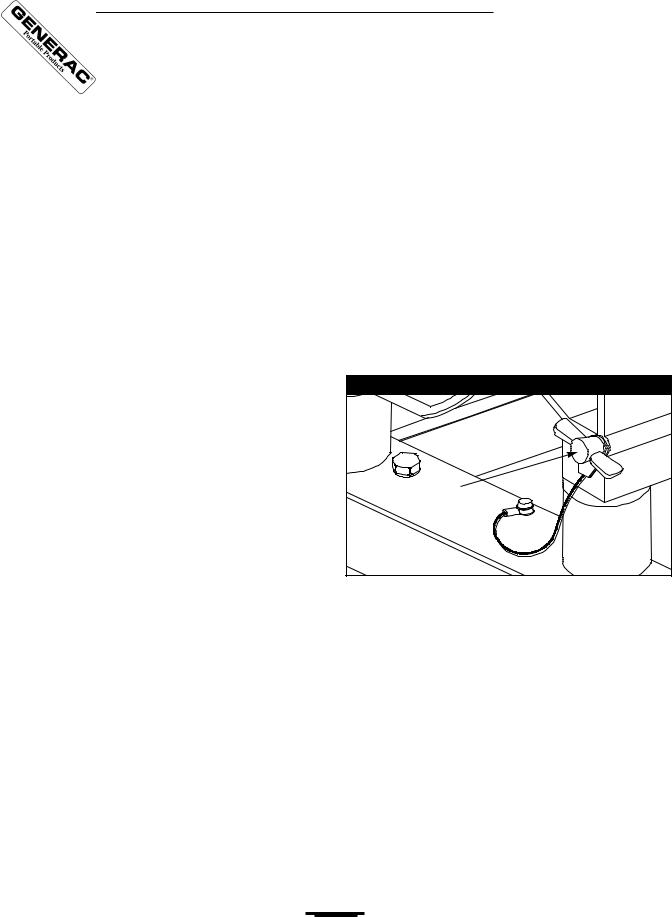
CHECK BATTERY / ATTACH NEGATIVE BATTERY WIRE
The sealed battery on the generator is fully charged and pre–installed except for the negative (black) battery cable.
To install:
•Cut off tie wrap securing loose end of negative (black) cable.
•Remove nut and washer on the negative battery terminal.
•Slide the negative battery cable over the screw on the negative terminal (Figure 2).
Figure 2 — Negative Battery Connection
|
|
Nut |
|
|
Washer |
|
Negative |
|
|
battery |
Screw |
|
cable |
|
|
Positive battery cable |
|
|
|
|
• |
Reattach washer and nut and tighten. |
|
•Verify that the connections to the battery and generator are tight and secure.
4
Generac Portable Products 7000EXL Extended Life Generator
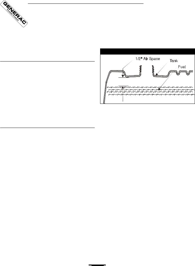
BEFORE STARTING THE ENGINE
•Slowly add unleaded regular gasoline to fuel tank. Be careful not to overfill.Allow about 1/2" of tank space for fuel expansion (Figure 3).
Figure 3 — Typical Fuel Expansion Space
Add Oil
CAUTION! Any attempt to crank or start the engine before it has been properly filled with the recommended oil may result in an engine failure.
To fill your engine with oil:
•Place generator on a level surface.
•Follow the oil grade recommendations and oil fill instructions given in the engine owner’s manual.
NOTE: The generator’s revolving field rides on a prelubricated and sealed ball bearing that requires no additional lubrication for the life of the bearing.
Add Gasoline
 WARNING! Never fill fuel tank indoors. Never fill fuel tank when engine is running or hot. Do Not light a cigarette or smoke when filling the fuel tank.
 WARNING! Do Not overfill the fuel tank. Always allow room for fuel expansion.
•Use regular UNLEADED gasoline with the generator engine. Do Not use premium gasoline. Do Not mix oil with gasoline.
•Clean area around fuel fill cap, remove cap.
• Install fuel cap and wipe up any spilled gasoline.
IMPORTANT: It is important to prevent gum deposits from forming in essential fuel system parts, such as the carburetor, fuel filter, fuel hose or tank during storage.Also, experience indicates that alcohol–blended fuels (called gasohol, ethanol or methanol) can attract moisture, which leads to separation and formation of acids during storage. Acidic gas can damage the fuel system of an engine while in storage. Be sure to review the precautions given in “Storage” on page 13.
Never use engine or carburetor cleaner products in the fuel tank or permanent damage may occur.
5
Generac Portable Products 7000EXL Extended Life Generator
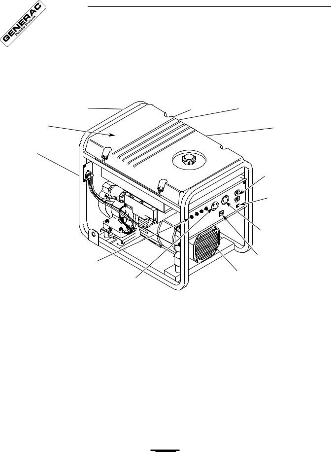
KNOW YOUR GENERATOR
Read this owner’s manual and safety rules before operating your generator.
Compare the illustrations with your generator, to familiarize yourself with the locations of various controls and adjustments. Save this manual for future reference.
Air Cleaner |
Choke Lever |
Run/Stop Switch |
Fuel Tank |
|
Spark Arrester Muffler |
Start Button
|
120 Volt AC, 20 Amp |
|
Duplex Receptacle |
|
Idle Control Switch |
|
120/240 Volt AC, |
|
30 Amp Receptacle |
|
12 Volt DC, 10 Amp |
Circuit Breakers (AC) |
Receptacle |
|
|
120 Volt AC, 30 Amp |
Grounding Wing Nut |
Receptacle |
|
12 Volt DC,10 Amp Receptacle — Recharge a discharged 12 Volt automotive type battery through this receptacle.
120 Volt AC, 20 Amp, Duplex Receptacle — May be used to supply electrical power for the operation of
120 Volt AC, 20 Amp, single phase, 60 Hz electrical lighting, appliance, tool and motor loads.
120 Volt AC, 30 Amp Locking Receptacle — May be used to supply electrical power for the operation of
120 Volt AC, 30 Amp, single phase, 60 Hz electrical lighting, appliance, tool and motor loads.
120/240 Volt AC, 30 Amp Locking Receptacle — May be used to supply electrical power for the operation of 120 and/or 240 Volt AC, 30 Amp, single phase, 60 Hz electrical lighting, appliance, tool and motor loads.
Air Cleaner — Uses a dry type filter element and foam pre–cleaner to limit the amount of dirt and dust sucked into the engine.
Choke Lever — Used when starting a cold engine.
Circuit Breakers (AC) — Each receptacle is provided with a "push to reset" circuit breaker to protect the generator against electrical overload.
Fuel Tank — Capacity of seven (7) U.S. gallons.
Grounding Wing Nut — Used for proper grounding of unit.
Idle Control Switch — With this switch set to ON, generator automatically reduces engine speed when no load is connected and increases engine to proper speed when load is applied. However, be sure switch is OFF when starting engine.
Run/Stop Switch — Set this switch to "Run" before starting engine. Set switch to "Stop" to switch OFF engine.
Spark Arrester Muffler — Exhaust muffler lowers engine noise and is equipped with a spark arrester screen. Start Button — When pressed, cranks engine to start.
6
Generac Portable Products 7000EXL Extended Life Generator
OPERATING THE
4.Place the choke lever in the “Full” choke position (Figure 7).
GENERATOR
Figure 7 — Choke Positions
 CAUTION! Never start or stop unit with electrical loads connected AND with the connected devices turned ON.
IMPORTANT: Always unplug the battery float charger before starting the generator.
Starting the Engine
Disconnect all electrical loads from the generator. Use the following start instruction steps by numerical order:
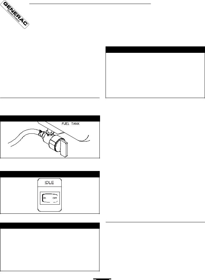
1.Turn the fuel valve to the “On” position (Figure 4).
Figure 4 — Fuel Valve
Fuel Valve is shown |
in the On position |
2.Make sure the Idle Control switch is in “Off” position (Figure 5).
Figure 5 — Idle Control Switch
3.Set the Run/Stop switch to “Run” position (Figure 6).
Figure 6 — Run/Stop Switch
5A. For electric starting, press start switch on generator cradle.To prolong the life of the starter components, press the starter button for no more than 15 seconds, and pause for 30 seconds.
5B. For manual starting, grasp the recoil handle and pull slowly until slight resistance is felt.Then pull rapidly one time only to start engine.
•If engine starts, proceed to step 7.
•If engine fails to start, proceed to step 6.
6.Move the choke lever to “Half” choke position, and pull recoil handle twice.
•If engine fails to start, repeat steps 4 thru 6.
7.Move choke lever to “Run” position. If engine falters, move choke lever to “Half” choke position until the engine runs smoothly and then to “Run” position.
NOTE: If engine still fails to start after 3 pulls, check for proper oil level in crankcase.This unit is equipped with a Low Oil Shutdown System. See engine manual.
Refer to the engine owner’s manual for complete starting instructions.
Connecting Electrical Loads
•Let engine stabilize and warm up for a few minutes after starting.
•Plug in and turn on the desired 120 and/or 240 Volt AC, single phase, 60 Hz electrical loads.
•Do Not connect 240 Volt loads to the 120 Volt receptacles.
•Do Not connect 3–phase loads to the generator.
•Do Not connect 50 Hz loads to the generator.
7
Generac Portable Products 7000EXL Extended Life Generator
•DO NOT OVERLOAD THE GENERATOR. Add up the rated watts (or amps) of all loads to be connected at one time.This total should not be greater than the rated wattage/amperage capacity of the generator. See “Don’t Overload the Generator” on page 11.
Stopping the Engine
•Unplug all electrical loads from generator panel receptacles. Never start or stop engine with electrical devices plugged in and turned on.
•Put the idle control switch in the “Off” position.
•Let engine run at no–load for 30 seconds to stabilize the internal temperatures of engine and generator.
•Move run/stop switch to “Stop.”
•Close the fuel shut–off valve.
Operating Automatic Idle Control
This switch is designed to greatly improve fuel economy.
When this switch is turned ON, the engine will only run at its normal high governed engine speed when an electrical load is connected.When an electrical load is removed, the engine will run at a reduced speed. With the switch off, the engine will run at the normal high engine speed. Always have the switch off when starting and stopping the engine.
Charging a Battery
 WARNING! Storage batteries give off explosive hydrogen gas while recharging.An explosive mixture will remain around the battery for a long time after it has been charged.The slightest spark can ignite the hydrogen and cause an explosion, resulting in blindness or other serious injury.
 WARNING! Do Not permit smoking, open flame, sparks or any other source of heat around a battery.Wear protective goggles, rubber apron and rubber gloves when working around a battery. Battery electrolyte fluid is an extremely caustic sulfuric acid solution that can cause severe burns. If spill occurs flush area with clear water immediately.
Your generator has the capability of recharging a discharged 12 Volt automotive or utility style storage battery. Do Not use the unit to charge any 6 Volt batteries. Do Not use the unit to crank an engine having a discharged battery.
To recharge 12 Volt batteries, proceed as follows:
•Check fluid level in all battery cells. If necessary, add ONLY distilled water to cover separators in battery cells.
Do Not use tap water.
•If the battery is equipped with vent caps, make sure they are installed and are tight.
•If necessary, clean battery terminals.
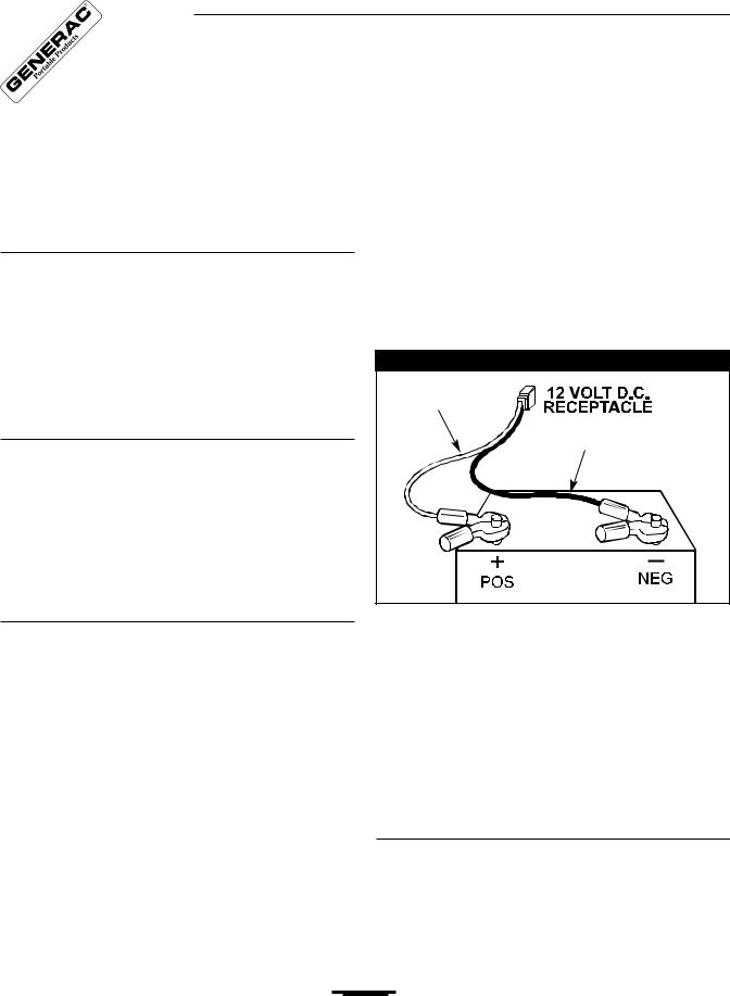
•Connect battery charge cable connector plug to panel receptacle identified by the words “12 VOLTS D.C.”
•Connect battery charge cable clamp with red handle to the positive (+) battery terminal (Figure 8).
Figure 8 — Battery Charge Cable Connection
Red |
Black |
•Connect battery charge cable clamp with black handle to the negative (–) battery terminal (Figure 8).
•Start engine. Let the engine run while battery recharges.
•When battery has charged, shut down engine
NOTE: Use an automotive hydrometer to test battery state of charge and condition. Follow the hydrometer manufacturer’s instructions carefully. Generally, a battery is considered to be at 100% state of charge when specific gravity of its fluid (as measured by hydrometer) is 1.260 or higher.
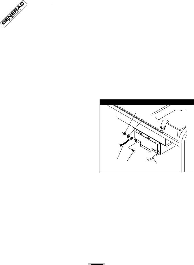
How to Use the Battery Charger
Use battery float charger jack to keep the starting battery charged and ready for use. Battery charging should be done in a dry location, such as inside a garage.
•Plug the charger into the unit’s “Battery Float Charger” jack, which is located on the starter switch (Figure 9). Plug battery charger into a 120 Volt AC wall receptacle.
8
 Loading...