


GENERAC
Portable Generator
Power Transfer System with Dual Load Manager™ Owner’s Manual
|
|
|
Problems? |
|||||||
|
|
Questions? |
||||||||
Before |
taking |
your |
|
|||||||
|
back to |
|
system |
|||||||
|
call |
the |
|
the |
|
|||||
|
|
|
|
|
|
|
store, |
|||
1– |
|
|
|
|
generator |
|||||
|
helpline |
at |
|
|||||||
|
800– |
|
|
|
|
|
||||
M |
|
|
270– |
1408 |
||||||
|
|
–F 8– |
|
|
|
|||||
|
|
|
|
|
|
5 CT |
|
|||
CONTENTS:
Installation Instructions - - - - - - - - - - - -Page 1 through 12
Owner’s Operating Procedure - - - - - -Page 13 through 16
IMPORTANT
This product must be installed in compliance with local residential wiring and electrical codes by a licensed electrician or qualified professional. Generac Portable Products is not responsible for damaged equipment, accidents, or personal injury caused by incorrect installation.
Read this Safety Manual and Instructions BEFORE operating Power Transfer System.
DESCRIPTION
The Model 1403 Power Transfer System safely connects up to twelve essential household loads, such as the furnace fan, freezer, refrigerator, water well pump, sump pump, lighting or outlet circuits to either the utility power or a portable generator. In the event of a utility power failure, the homeowner can safely select devices to be powered by an outdoor portable generator. Self-contained load meters assist the operator when managing power loads. The power transfer system will not permit connection to both utility and generator power at the same time.
The Model 1403 Power Transfer System is easy for a licensed electrician or qualified professional to install, safe for a homeowner to operate, and will work with 240 Volt AC generators factory equipped with a NEMA type 14-50R receptacle.
This manual contains important warnings and information. READ AND RETAIN FOR REFERENCE.
Model No. 1403-0 Power Transfer System Manual No. B4610 (Revision 2, 1/28/2000)
This symbol points out important safety instructions, which, if not followed, could endanger the personal safety and/or property of yourself and others. Read and follow all instructions in the manual before attempting to operate this unit.

Generac Portable Products Power Transfer System
NOTE: The maximum load allowed through each Load Manager™ switch is 7200 Watts: 30 Amps at 240 Volts or 60 Amps at 120 Volts.
Per National Electric Code, connection of a generator to any electrical circuit normally powered by an electric utility must be by means of approved transfer switch equipment so as to isolate the electrical circuit from the utility distribution system when the generator is operating. Failure to isolate the electrical circuits by such means may result in injury or death to utility power workers due to backfeed of electrical energy.
CAUTION: Each Load Manager™ switch is for indoor use only. The connection box is a NEMA type 3R, intended for outdoor use.
NEMA stands for National Electrical Manufacturer’s Association.
UNPACKING
Remove the Power Transfer System components from the shipping carton. Each Load Manager™ switch is completely prewired and ready for installation. Inspect the switches and attached wires and flexible conduit for any shipping damage.
The connection box is supplied ready to be wired. Inspect the box, the connection cord set, and the connecting plug for any damage.
The installer will select and attach the connecting cord plug, as described in the Installation Procedure,
step 22.
Items Not Shipped with Power Transfer System:
The following items, required for system installation, are not included and must be provided by the installer:
1. Tools required for installation
GENERATOR
COMPATIBILITY
Only use a generator that is factory-equipped with a NEMA Type 14-50R receptacle.
NEVER use a generator equipped with a 3-prong 240 Volt receptacle because damage may occur in connected appliances.
CARTON CONTENTS
Items in the shipping carton include:
•Two Load Manager™ Switches
•Connecting Box
•Connecting Cord Set
•50 Amp Connecting Plug
•“Attention” Decal
If any of the above parts are missing or damaged, call the Generac helpline at 1–800–270–1408.
2.Anchors and screws to mount the power transfer system components and conduit.
3.Junction box(s), conduit, fittings, wire nuts, and insulated copper wire for connecting the Load Manager™ switches to the outside connection box.
SPECIFICATIONS |
|
Model Number....................................................... |
1403 |
Maximum Circuits...................................................... |
12 |
Maximum Load/Circuit from Generator ........... |
15 Amps |
Maximum Load/Circuit from Load Center ....... |
20 Amps |
Maximum Watts per Load Manager™................... |
7200 |
Connecting Cord Length ......................................... |
8 ft. |
2

Generac Portable Products Power Transfer System
GENERAL SAFETY
INFORMATION
1.A licensed electrician or qualified professional (referred to herein as “installer”) must install the power transfer system per local code.
2.During installation, the installer is required to remove the cover from the building power distribution panel (referred to herein as a ‘load center’.) To reduce the risk of electrical shock, the Main circuit breaker must be turned OFF while the load center cover is removed.
3.DO NOT OVERLOAD THE GENERATOR. Overloading a generator in excess of its rated wattage capacity will trip generator circuit breakers.
4.Always plug the connecting cord set into the connection box and generator BEFORE starting the generator. Always shut the generator down before detaching the cord set.
5.Portable generators attached to this Power Transfer System must be operated outside, in accordance with warnings and instructions found in the generator’s Owner’s Manual.
PLAN THE INSTALLATION
The installer and the homeowner decide which circuits are to be powered by the generator during a utility power outage:
•The plan should ensure that no single circuit load exceeds 15 Amps.
•The plan should also identify circuits that exceed the 15 Amp maximum.
•During generator operation, the homeowner should use only necessary household items and to alternate use of larger loads, such as water pump or electric skillet. The installer will instruct the homeowner in appropriate load management techniques.
Three methods of determining loads are given here:
Measure Actual Loads
The installer uses a clamp-on ammeter to measure each of the actual desired loads to ensure each total circuit draws less than 15 Amps.
Sum Loads from Data Plates
The installer inspects each desired device, notes current consumption found on labels on each appliance, then adds all loads on each circuit:
•The rated current of appliances and motors can usually be found on a data plate or decal affixed to the device.
•The rated wattage of lights can be taken from light bulbs.
•Some electric motors, such as induction types, require about three times more power for starting than for running. This surge of power lasts for only a few seconds when starting such motors. Be sure to allow for this high starting load.
Estimate Loads
The third method estimates total circuit loads based on information given in Figure 1.
Figure 1 — Load Reference Guide
APPLIANCE ~ ~ ~ ~ ~ ~ ~ ~ ~ ~ ~ ~ ~ ~ ~ ~LOAD DRAW
Air Conditioner (12,000 BTU) ~ ~ ~ ~ ~(1700W) 7A@240V Coffee Maker ~ ~ ~ ~ ~ ~ ~ ~ ~ ~ ~ ~(1000W) 8.4A@120V
*Electric Range (one element) ~ ~ ~(1500W) 6.3A@240V |
|
Electric Blanket |
~ ~ ~ ~ ~ ~ ~ ~ ~ ~(1500W) 12.5A@120V |
Electric Skillet |
~ ~ ~ ~ ~ ~ ~ ~ ~ ~ ~(1250W) 10.5A@120V |
*Freezer ~ ~ ~ ~ ~ ~ ~ ~ ~ ~ ~ ~ ~ ~ ~(500W) 4.2A@120V
*Furnace Fan (1/3 HP) |
~ ~ ~ ~ ~ ~ ~(1200W) 10A@120V |
||
*Jet Pump |
~ ~ ~ ~ ~ ~ ~ ~ ~ ~ ~ ~ ~ ~(800W) 3.4A@240V |
||
Light Bulb |
~ ~ ~ ~ ~ ~ ~ ~ ~ ~ ~ ~ ~ ~(100W) 0.9A@120V |
||
Microwave Oven ~ ~ ~ ~ ~ ~ ~ ~ ~ ~ ~(700W) 5.9A@120V |
|||
Oil Burner on Furnace |
~ ~ ~ ~ ~ ~ ~ ~(300W) 2.5A@120V |
||
Oil Fired Heater (30,000 BTU) |
~ ~ ~ ~(150W) 1.3A@120V |
||
Oil Fired Heater (85,000 BTU) |
~ ~ ~ ~(225W) 1.9A@120V |
||
Oil Fired Heater (140,000 BTU) |
~ ~ ~(400W) 3.4A@120V |
||
Radio ~ ~ ~ ~ ~ ~ ~ ~ ~ ~(50 to 200W) 0.5 to 1.7A@120V *Refrigerator ~ ~ ~ ~ ~ ~ ~ ~ ~ ~ ~ ~ ~ ~(600W) 5A@120V *Submersible Well Pump (1 HP) ~ ~(2000W) 8.4A@240V Sump Pump ~ ~ ~ ~ ~ ~ ~ ~ ~ ~ ~ ~ ~ ~(600W) 5A@120V Television ~ ~ ~ ~ ~ ~ ~ ~(200 to 500W) 1.7 to 4.2A@120V
* Allow 3 times the listed watts for starting these devices. WATTS = AMPS x VOLTS
3
Generac Portable Products Power Transfer System
INSTALLATION
PROCEDURE
Load Manager™ Switch
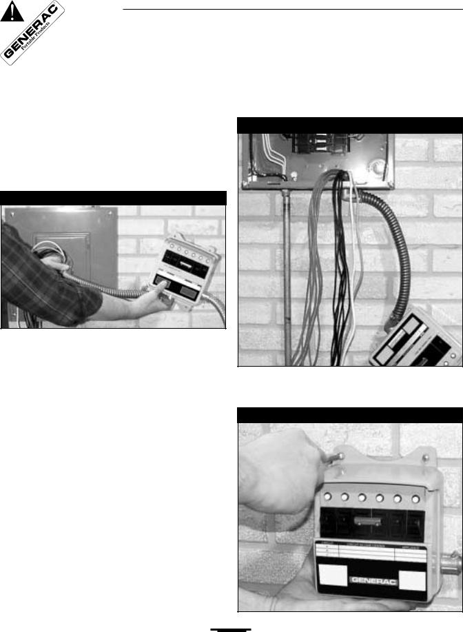
Before removing the load center cover, plan mounting location for both Load Manager™ switches. To do so, hold a Load Manager™ switch about 18 inches from the center of the load center, as shown in Figure 2.
Figure 2 — Planning Switch Location
NOTE: The following procedure describes the installation of one Load Manager™ switch. Use identical instructions to install and test the second Load Manager™ switch.
1.Ensure there is enough room to mount both Load Manager™ switches so their flex conduit attaches directly to the load center.
2.Identify appropriate vacant load center 3/4” knockouts.
DANGER: Contact with wires and terminals inside the load center must be avoided as contact may result in dangerous electrical shock. Before removing the load center cover, switch OFF the main circuit breaker serving the load center. Remember that wires on the line side of the main circuit breaker are electrically dangerous.
3.Turn OFF the load center’s main circuit breaker, then remove the load center cover.
4.Remove the predetermined knockouts. Route all wires extending from the flexible conduit attached to a Load Manager™ switch through the empty
hole, as shown in Figure 3. Secure the conduit connector to the load center with the supplied lock nut.
Figure 3 — Wire Loom from Switch
5.Anchor the Load Manager™ switch to the wall at the selected position, as shown in Figure 4.
Figure 4 — Anchoring Load Manager™ Switch
4

Generac Portable Products Power Transfer System
6.From the load management plan, determine the load that is to be connected to Load Manager™ switch circuit “A”. Turn that load center circuit breaker to its “OFF” position. Loosen the screw that retains the wire to this breaker, then detach the wire. Figure 5 shows the selected load wire detached from the circuit breaker.
Figure 5 — Wire Detached From Breaker
Wire removed
7.Find the black and red wires marked “A” that come from the Load Manager™ switch. Using good workmanship, route both of these wires near the selected circuit breaker. Trim and strip the red “A” wire and install it properly into the circuit breaker.
8.Trim and strip the black “A” wire to mate with the wire previously detached from the breaker. Secure the wire ends with a wire nut. Neatly dress the wires into the load center, as shown in Figure 6.
Figure 6 — Single-pole Connection
IMPORTANT:The installer should never cross the black and red leads from the Load Manager™ switch. Doing so will void the warranty and could cause significant damage to Load Manager™ components and the generator.
Make Sure:
•The RED wire from the Load Manager™ switch is always connected to the circuit breaker.
•The BLACK wire from the Load Manager™ switch is always connected to the wire going to the load.
DANGER! You must connect the Load
Manager™ switch wires as described or serious damage to the equipment or yourself may result.
9.Select the load center circuit that will become load management circuit “B”. Repeat Steps 6 through 8 for the red and black wires marked “B” coming from the Load Manager™ switch.
10.If you wish to connect a 240 Volt AC two-pole circuit, such as a well pump, proceed as follows:
a.Turn off the two-pole circuit breaker used for the pump circuit and detach the load wires from that breaker.
b.Select the four wires marked “C” and “D” coming from the Load Manager™ switch conduit and route them close to the selected circuit breaker(s).
c.Repeat Steps 6 through 8 for each pair of red and black wires “C” and “D”.
d.A typical two-pole circuit connection is shown in simplified form in Figure 7.
Figure 7 — Two-pole Connection
5
 Loading...