


BELT-DRIVE STRAIGHT ARM TURNTABLE
PLATTENSPIELERMITRIEMENANTRIEBUNDGERADEMTONARM GIRADISCOS DE BRAZO RECTO TRACCIÓN POR CORREA
PLATINEVINYLEAVECENTRAÎNEMENTPARCOURROIEETBRASDROIT
OPERATIONS MANUAL
BEDIENUNGSHANDBUCH
MANUAL DEL OPERADOR
MANUEL D’INSTRUCTIONS
MULTI LANGUAGE INSTRUCTIONS
ENGLISH.......................................................................................................................................................................................................................................................................... |
PAGE 4 |
DEUTSCH......................................................................................................................................................................................................................................................................... |
PAGE 6 |
ESPAÑOL.................................................................................................................................................................................................................................................................................................................................................................. |
PAGE 8 |
FRANCAIS.................................................................................................................................................................................................................................................................................................................................................................... |
PAGE 10 |
PLEASE READ BEFORE USING APPLIANCE, IMPORTANT WARNING & SAFETY INSTRUCTIONS!
CAUTION
RISK OF ELECTRICAL SHOCK DO NOT OPEN!
CAUTION: This product satisfies FCC regulations when shielded cables and connectors are used to connect the unit to other equipment. To prevent electromagnetic interference with electric appliances such as radios and televisions, use shielded cables and connectors for connec tions.
The exclamation point within an equilateral triangle is intended to alert the user to the presence of important operating and maintenance (servicing) instructions in the literature accompanying the appliance.
The lightning flash with arrowhead symbol, within an equilateral triangle, is intended to alert the user to the presence of uninsulated “dangerous voltage” within the product’s enclosure that may be of sufficient magnitude to constitute a risk of electric shock to persons.
READ INSTRUCTIONS: All the safety and operating instructions should be read before the product is operated.
RETAIN INSTRUCTIONS: The safety and operating instructions should be retained for future reference.
HEED WARNINGS: All warnings on the product and in the operating instructions should be adhered to.
FOLLOW INSTRUCTIONS: All operating and use instructions should be followed.
CLEANING: The product should be cleaned only with a polishing cloth or a soft dry cloth. Never clean with furniture wax, benzine, insecticides or other volatile liquids since they may corrode the cabinet.
ATTACHMENTS: Do not use attachments not recommended by the product manu facturer as they may cause hazards.
WATER AND MOISTURE: Do not use this product near water, for example, near a bathtub, wash bowl, kitchen sink, or laundry tub; in a wet basement; or near a swimming pool; and the like.
ACCESSORIES: Do not place this product on an unstable cart, stand, tripod, brack et, or table. The product may fall, causing serious injury to a child or adult, and seri ous damage to the product. Use only with a cart, stand, tripod, bracket, or table recommended by the manufacturer, or sold with the product. Any mounting of the product should follow the manufacturer’s instructions, and should use a mounting accessory recommended by the manufacturer.
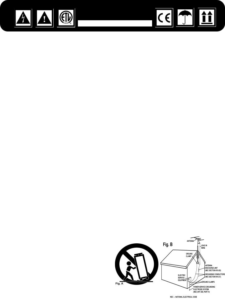
CART: A product and cart combination should be moved with care. Quick stops, excessive force, and uneven surfaces may cause the product and cart combina tion to overturn. See Figure A.
VENTILATION: Slots and openings in the cabinet are provided for ventilation and to ensure reliable operation of the product and to protect it from overheating, and these openings must not be blocked or covered. The openings should never be blocked by placing the product on a bed, sofa, rug, or other similar surface. This product should not be placed in a built-in installation such as a bookcase or rack unless proper ventilation is provided or the manufacturer’s instructions have been adhered to.
POWER SOURCES: This product should be operated only from the type of power source indicated on the marking label. If you are not sure of the type of power sup ply to your home, consult your product dealer or local power company.
LOCATION: The appliance should be installed in a stable location.
NON-USE PERIODS: The power cord of the appliance should be unplugged from the outlet when left unused for a long period of time.
GROUNDING OR POLARIZATION:
•If this product is equipped with a polarized alternating current line plug (a plug having one blade wider than the other), it will fit into the outlet only one way. This is a safety feature. If you are unable to insert the plug fully into the outlet, try reversing the plug. If the plug should still fail to fit, contact your electrician to replace your obsolete outlet. Do not defeat the safety purpose of the polarized plug.
•If this product is equipped with a three-wire grounding type plug, a plug having a third (grounding) pin, it will only fit into a grounding type power outlet. This is a safety feature. If you are unable to insert the plug into the outlet, contact your electrician to replace your obsolete outlet. Do not defeat the safety purpose of the grounding type plug.
POWER-CORD PROTECTION: Power-supply cords should be routed so that they are not likely to be walked on or pinched by items placed upon or against them, paying particular attention to cords at plugs, convenience receptacles, and the point where they exit from the product.
OUTDOOR ANTENNA GROUNDING: If an outside antenna or cable system is connected to the product, be sure the antenna or cable system is grounded so as to provide some protection against voltage surges and built-up static charges. Article 810 of the National Electrical Code, ANSI/NFPA 70, provides information with regard to proper grounding of the mast and supporting structure, grounding of the lead-in wire to an antenna discharge unit, size of grounding conductors, loca
tion of antenna-discharge unit, connection to grounding electrodes, and requirements for the grounding electrode. See Figure B.
LIGHTNING: For added protection for this product during a lightning storm, or when it is left unattended and unused for long periods of time, unplug it from the wall out let and disconnect the antenna or cable system. This will prevent damage to the product due to lightning and power-line surges.
POWER LINES: An outside antenna system should not be located in the vicinity of overhead power lines or other electric light or power circuits, or where it can fall into such power lines or circuits. When installing an outside antenna system, extreme care should be taken to keep from touching such power lines or circuits as contact with them might be fatal.
OVERLOADING: Do not overload wall outlets, extension cords, or integral conven ience receptacles as this can result in a risk of fire or electric shock.
OBJECT AND LIQUID ENTRY: Never push objects of any kind into this product through openings as they may touch dangerous voltage points or short-out parts that could result in a fire or electric shock. Never spill liquid of any kind on the product.
SERVICING: Do not attempt to service this product yourself as opening or removing covers may expose you to dangerous voltage or other hazards. Refer all servicing to qualified service personnel.
DAMAGE REQUIRING SERVICE: Unplug this product from the wall outlet and refer servicing to qualified service personnel under the following conditions:
•When the power-supply cord or plug is damaged.
•If liquid has been spilled, or objects have fallen into the product.
•If the product has been exposed to rain or water.
•If the product does not operate normally by following the operating instructions. Adjust only those controls that are covered by the operating instructions as an improper adjustment of other controls may result in damage and will often require extensive work by a qualified technician to restore the product to its normal oper ation.
•If the product has been dropped or damaged in any way.
•When the product exhibits a distinct change in performance, this indicates a need for service.
REPLACEMENT PARTS: When replacement parts are required, be sure the service technician has used replacement parts specified by the manufacturer or have the same characteristics as the original part. Unauthorized substitutions may result in fire, electric shock, or other hazards.
SAFETY CHECK: Upon completion of any service or repairs to this product, ask the service technician to perform safety checks to determine that the product is in proper operating condition.
WALL OR CEILING MOUNTING: The product should not be mounted to a wall or ceil ing.
HEAT: The product should be situated away from heat sources such as radiators, heat registers, stoves, or other products (including amplifiers) that produce heat.
(2)

TT-01
(3)
INTRODUCTION:
Congratulations on purchasing a Gemini TT-01 belt drive manual turntable. This state of the art turntable includes the latest features.
Prior to use, we suggest that you carefully read all the instructions.
FEATURES
•+/-10% Variable pitch slider
•Solid aluminum platter
•Straight tonearm for superior tracking
•Fully adjustable counter weight & anti-skating controls
•Dual speed RPM (33/45)
•LED Illuminated soft touch start/stop & RPM buttons
•Removable head shell
•CN-25 cartridge & felt slipmat included
•RCA & ground cables
PRECAUTIONS:
1.Read all operating instructions before using this equipment.
2.The apparatus should not be exposed to dripping or splashing, and no objects filled with liquids such as vases should be placed on the apparatus.
3.To reduce the risk of electrical shock, do not open the unit. THERE ARE NO USER REPLACEABLE PARTS INSIDE. Please contact the
Gemini Service Department or your authorized dealer to speak to a qualified service technician.
4.Tone Arm bearings are factory set and sealed. Any attempt at adjustment will void the warranty.
5.Be sure that all AC power is OFF while making connections.
6.Cables should be low capacitance, shielded and of proper length. Make sure that all plugs and jacks are tight and properly connected.
7.Always, begin with the audio level faders/volume controls set at minimum and the speaker volume control(s) set to OFF. Wait 8 to 10 seconds prior to turning up the speaker volume to prevent the transient “POP” that could result in speaker/crossover damage.
8.DO NOT EXPOSE THIS UNIT TO RAIN OR MOISTURE.
9.DO NOT USE ANY SPRAY CLEANER OR LUBRICANT ON ANY CONTROLS OR SWITCHES.
PARTS CHECKLIST: |
|
Please make sure the following parts are included with your TT-01: |
|
Turntable unit......................................................................................... |
1 |
Turntable platter.................................................................................... |
1 |
Slipmat.................................................................................................. |
1 |
Counterweight....................................................................................... |
1 |
Headshell with cartridge...................................................................... |
1 |
ASSEMBLY & SET-UP: |
|
SEE FIG. 3 FOR PART NUMBERS AND LOCATIONS.
VOLTAGE SELECTION:
Rotate the PLATTER (2) until the VOLTAGE SELECTOR (3) (located on the TURNTABLE BASE (1)) is visible through one of the platter holes. Make sure that the VOLTAGE SELECTOR (3) switch is set to the correct voltage.
WARNING: IF YOU TRY TO OPERATE THE TURNTABLE WITH THE INCORRECT VOLTAGE SETTING, IT CAN DAMAGE YOUR TURNTABLE.
ATTACHING THE TURNTABLE BELT:
The TURNTABLE BELT (4) comes attached to the underside of the PLATTER (2) and the MOTOR SPINDLE (5) but can some times detach in shipping. Rotate the PLATTER (2) and look through the platter holes to check if belt detached. If the belt is not wrapped tightly around the platter and the MOTOR SPINDLE (5), you need to reattach it.
1. Remove the platter and wrap the belt around the inner circle under the platter. DO NOT STRETCH OUT THE BELT!
2. Replace the platter and rotate the PLATTER (2) until the MOTOR SPINDLE (5) is visible, then fit your fingers in hole on the top of the
PLATTER (2), feel for and grab the rubber belt and attach to the motor spindle.
3. Replace the locking washer.
TURNTABLE INSTALLATION:
1.Put the SLIPMAT (6) on the PLATTER (2).
2.Set the TURNTABLE BASE (1) on a flat, level surface free of vibration. Use the turntable feet to stabilize the unit horizontally.
3.Try to place the unit as far away from the speakers as possible.
4.Keep the unit away from direct exposure to the sun, heat, moisture or dirt.
5.Keep the unit well ventilated.
CARTRIDGE INSTALLATION: (SEE FIG. 1)
Because all cartridges have their own designs, please refer to your particular cartridge’s instructions to insure proper installation. If you are using a pre-mounted or integrated cartridge, you can jump ahead to HEADSHELL INSTALLATION:
1. Connect the lead wires to the cartridge terminals. For your convenience, the terminals of most cartridges are color-coded. Connect each lead wire to the terminal of the same color. Incase your cartridge is not marked the positive leads are the ones on top negative below, left are left, and right is right.
White (L+)........................................................................ |
Left Channel + |
Blue (L-)............................................................................. |
Left Channel - |
Red (R+)......................................................................... |
Right Channel + |
Green (R-)....................................................................... |
Right Channel - |
2. Mount the cartridge in the HEADSHELL (7) and tighten it with the screws included with the cartridge.
HEADSHELL INSTALLATION:
Insert the HEADSHELL (7) into the front of the tubular TONE ARM
(9). While holding the HEADSHELL (7) firmly in a horizontal position, turn the LOCKING NUT (8) counter clockwise until the HEADSHELL
(7) is locked in place.
COUNTERWEIGHT INSTALLATION: (SEE FIG. 2)
1.Slide the COUNTERWEIGHT (10) onto the rear of the TONE ARM
(9) with the numbered stylus gauge facing forward.
2.Twist the COUNTERWEIGHT (10) counter clockwise lightly, to screw it onto the rear of the TONE ARM (9).
ADJUSTING HORIZONTAL ZERO (0) BALANCE AND STYLUS PRESSURE:
1.Without touching the stylus tip, remove the stylus protector (if your cartridge has a detachable one).
2.Release the ARM CLAMP (12) and lift the TONE ARM (9) off the
ARM REST (13).
3.Counter clockwise advancement of the COUNTERWEIGHT (10) will cause the cartridge side of the TONE ARM (9) to be lowered; turning it clockwise will cause the opposite. Turn the COUNTERWEIGHT (10) clockwise or counter clockwise as needed until the TONE ARM (9) is balanced horizontally. You can easily tell this by watching for the point where the TONE ARM (9) “floats” freely.
4.Place TONE ARM (9) on ARM REST (13) and lock it in place with the ARM CLAMP (12).
5.With the TONE ARM (9) locked on the ARM REST (13), hold the COUNTERWEIGHT (10) steady with one hand while rotating the STYLUS PRESSURE RING (11) until the numeral “0” on the ring
aligns with the center line on the TONE ARM (9) rear shaft. The horizontal zero (0) balance should be completed.
(4)
 Loading...