


GE PFDN440, PFMN445, PFDS450, PFMS455, PFDS455 User Manual 2
...DryersProfile
Printed in Mexico
GEAppliances.com
Safety Instructions . . . . . . . . . . . 2–4
Operating Instructions
Controls. . . . . . . . . . . . . . . . . . . . . . . . . . . 5–8
Cycle Options . . . . . . . . . . . . . . . . . . . . 9, 10
Smart Appliance . . . . . . . . . . . . . . . . . . . .13
Dryer Features . . . . . . . . . . . . . . . . . .10, 11
Quick Start Guide . . . . . . . . . . . . . . . . . . . .5
Settings Option. . . . . . . . . . . . . . . . . . . . . .10
Using the Dryer . . . . . . . . . . . . . . . . . . . . .11
Installation Instructions
Before You Begin. . . . . . . . . . . . . . . .14, 15 Connecting the Inlet Hoses . . . . . . . . .17 Connecting a Gas Dryer. . . . . . . . .18–21 Connecting an
Electric Dryer. . . . . . . . . . . . . . . . . . . .22–24 Exhausting the Dryer. . . . . . . . . . . .25–31 Final Setup . . . . . . . . . . . . . . . . . . . . . . . . . .32 Installing the Pedestal. . . . . . . . . . .43–45 Location of your Dryer . . . . . . . . . .15, 16 Reversing the Door Swing. . . . . . .33–39 Stacking the Washer
and Dryer . . . . . . . . . . . . . . . . . . . . . . .40–42
Troubleshooting Tips. . . . . . .46–49
Consumer Support
Consumer Support. . . . . . . . Back Cover
Warranty (Canada). . . . . . . . . . . . . . . . . 51
Warranty (U.S.) . . . . . . . . . . . . . . . . . . . . . 50
Owner’s Manual &
Installation Instructions
PFDS450
PFDS455
PFDN440
PFDN445
PFMS450
PFMS455
PFMN440
PFMN445
Sécheuses
Profile
Manuel d’utilisation et d’installation
La section française commence à la page 52
Secadoras
Profile
Manual del propietario e instalación
La sección en español empieza en la página 104
SAVE THESE INSTRUCTIONS
Write the model and serial numbers here:
Model # ______________
Serial # _______________
They are on the label on the front of the dryer behind the door.
234D2010P001 |
49-90472 03-13 GE |

IMPORTANT SAFETY INFORMATION. READ ALL INSTRUCTIONS BEFORE USING.
2
 WARNING!
For your safety, the information in this manual must be followed to minimize the risk of fire or explosion, electric shock, or to prevent property damage, personal injury, or death.
Do not store or use gasoline or other |
Installation and service must be |
flammable vapors and liquids in the |
performed by a qualified installer, |
vicinity of this or any other appliance. |
service agency or the gas supplier. |
WHAT TO DO IF YOU SMELL GAS:
1
2
3
Do not try to light a match, or cigarette, or turn on any gas or electrical appliance.
Do not touch any electrical switch; do not use any phone in your building.
Clear the room, building or area of all occupants.
4
5
Immediately call your gas supplier from a neighbor’s phone. Follow the gas supplier’s instructions carefully.
If you cannot reach your gas supplier, call the fire department.
California Safe Drinking Water and Toxic Enforcement Act
This act requires the governor of California to publish a list of substances known to the state to cause cancer, birth defects or other reproductive harm and requires businesses to warn customers of potential exposure to such substances.
Gas appliances can cause minor exposure to four of these substances, namely benzene, carbon monoxide, formaldehyde and soot, caused primarily by the incomplete combustion of natural gas or LP fuels.
Properly adjusted dryers will minimize incomplete combustion. Exposure to these substances can be minimized further by properly venting the dryer to the outdoors.
PROPER INSTALLATION
This dryer must be properly installed and located in accordance with the Installation Instructions before it is used. Installation Instructions are included in the back of this manual.
Properly ground dryer to conform with all governing codes and ordinances. Follow details in Installation Instructions.
Install or store where it will not be exposed to temperatures below freezing or exposed to water or weather.
Connect to a properly rated, protected and sized power supply circuit to avoid electrical overload.
Remove all sharp packing items and dispose of all shipping materials properly.
Exhaust/Ducting |
||
1 |
Dryers MUST be exhausted to the outside to prevent |
|
large amounts of moisture and lint from being blown |
||
|
||
|
into the room. |
|
2 |
Use only rigid metal 4” diameter ductwork inside the |
|
dryer cabinet. Use only UL approved rigid metal or |
||
|
||
|
flexible metal 4-in diameter ductwork for exhausting |
|
|
to the outdoors. Never use plastic or other |
|
|
combustible, easy-to-puncture ductwork. USE OF |
|
|
PLASTIC OR OTHER COMBUSTIBLE DUCTWORK CAN |
|
|
CAUSE A FIRE. PUNCTURED DUCTWORK CAN CAUSE |
|
|
A FIRE IF IT COLLAPSES OR BECOMES OTHERWISE |
|
|
RESTRICTED IN USE OR DURING INSTALLATION. |
|
For complete details, follow the Installation Instructions. |
||

IMPORTANT SAFETY INFORMATION. |
|
READ ALL INSTRUCTIONS BEFORE USING. |
GEAppliances.com |
 WARNING!
YOUR LAUNDRY AREA
Keep the area underneath and around your appliances free of combustible materials, (lint, paper, rags, etc.), gasoline, chemicals and other flammable vapors and liquids.
Keep the floor around your appliances clean and dry to reduce the possibility of slipping.
Close supervision is necessary if this appliance is used by or near children. Do not allow children to play on, with or inside this or any other appliance.
Keep the area around the exhaust opening and adjacent surrounding areas free from the accumulation of lint, dust and dirt.
Keep all laundry aids (such as detergents, bleaches, etc.) out of the reach of children, preferably in a locked cabinet. Observe all warnings on container labels to avoid injury.
Never climb on or stand on the dryer top.
WHEN USING YOUR DRYER
Never reach into the dryer while the drum is moving. Before loading, unloading or adding clothes, wait until the drum has completely stopped.
Clean the lint filter before each load to prevent lint accumulation inside the dryer or in the room. DO NOT
OPERATE THE DRYER WITHOUT THE LINT FILTER IN PLACE.
Do not wash or dry articles that have been cleaned in, washed in, soaked in or spotted with combustible or explosive substances (such as wax, oil, paint, gasoline, degreasers, dry-cleaning solvents, kerosene, etc.). These substances give off vapors that may ignite or explode. Do not add these substances to the wash water. Do not use or place these substances around your washer or dryer during operation.
Do not place items exposed to cooking oils in your dryer. Items contaminated with cooking oils may contribute to a chemical reaction that could cause a clothes load to catch fire.
Any article on which you have used a cleaning solvent or that contains flammable materials (such as cleaning cloths, mops, towels used in beauty salons, restaurants or barber shops, etc.) must not be placed in or near the dryer until solvents or flammable materials have been removed. There are many highly flammable items used in homes such as acetone, denatured alcohol, gasoline, kerosene, some household cleaners, some spot removers, turpentines, waxes, wax removers and products containing petroleum distillates.
The laundry process can reduce the flame retardancy of fabrics. To avoid such a result, carefully follow the garment manufacturer’s care instructions.
Do not dry articles containing rubber, plastic or similar materials such as padded bras, tennis shoes, galoshes, bath mats, rugs, bibs, baby pants, plastic bags, pillows, etc. that may melt or burn. Some rubber materials, when heated, can under certain circumstances produce fire by spontaneous combustion.
Do not store plastic, paper or clothing that may burn or melt on top of the dryer during operation.
Garments labeled Dry Away from Heat or Do Not Tumble Dry (such as life jackets containing Kapok) must not be put in your dryer.
Do not dry fiberglass articles in your dryer. Skin irritation could result from the remaining particles that may be picked up by clothing during subsequent dryer uses.
To minimize the possibility of electric shock, unplug this appliance from the power supply or disconnect the dryer at the household distribution panel by removing the fuse or switching off the circuit breaker before attempting any maintenance or cleaning (except the removal and cleaning of the lint filter).
NOTE: Pressing START/PAUSE or POWER does NOT disconnect the appliance from the power supply.
If you see water on the floor around the dryer, call for service.
Do not obstruct the flow of ventilating air. Do not stack or place laundry or throw rugs against the front or back of the dryer.
3

IMPORTANT SAFETY INFORMATION. READ ALL INSTRUCTIONS BEFORE USING.
 WARNING!
WHEN USING YOUR DRYER (cont.)
Neverattempttooperatethisapplianceifitisdamaged, malfunctioning, partially disassembled, or has missing or broken parts, including a damaged cord or plug.
The interior of the machine and the exhaust duct connection inside the dryer should be cleaned at least once a year by a qualified technician. See the Sorting and Loading Hints section on page 12.
If yours is a gas dryer, it is equipped with an
automatic electric ignition and does not have a pilot light. DO NOT ATTEMPT TO LIGHT WITH A MATCH. Burns may result from having your hand in the vicinity of the burner when the automatic ignition turns on.
Do not open the dryer door during steam cycles. The steam is very hot and it will continue to exhaust from the port for several seconds after opening. Do not touch the steam port after a steam cycle.
Do not use a steam cycle with items such as wool, leather, silk, lingerie, foam products or electric blankets.
Do not use steam cycles on new clothes without first washing.
You may wish to soften your laundered fabrics or reduce the static electricity in them by using a dryerapplied fabric softener or an anti-static conditioner. We recommend you use either a fabric softener in the wash cycle, according to the manufacturer’s instructions for those products, or try a dryer-added product for which the manufacturer gives written assurance on the package that their product can be safely used in your dryer. Service or performance problems caused by use of these products are the responsibility of the manufacturers of those products and are not covered under the warranty of this appliance.
Never attempt to use the Steam Dewrinkle or Steam Refresh cycles without clothes in the drum. Additionally, it is highly recommended to select the appropriate load size for best results. Selecting large load cycles for small loads may result in wetting of clothes, and selecting small load cycles for large loads may result in poor dewrinkling performance.
Do not spray any type of aerosol into, on, or near dryer at any trime. Do not use any type of spray cleaner when cleaning dryer interior. Hazardous fumes or electrical shock could occur.
WHEN NOT USING YOUR DRYER
 Grasp the plug firmly when disconnecting this appliance to avoid damage to the cord while pulling. Place the cord away from traffic areas so it will not be stepped on, tripped over or subjected to damage.
Do not attempt to repair or replace any part of this appliance or attempt any servicing unless specifically recommended in this Owner’s Manual or in published user-repair instructions that you understand and have the skills to carry out.
Before discarding a dryer, or removing it from service, remove the dryer door to prevent children from hiding inside.
Do not tamper with controls.
 READ AND FOLLOW THIS SAFETY INFORMATION CAREFULLY.
SAVE THESE INSTRUCTIONS
4
About the dryer control panel. |
GEAppliances.com |
 WARNING! To reduce the risk of fire, electric shock, or injury to persons, read the IMPORTANT SAFETY INSTRUCTIONS before operating this appliance.
Throughout this manual, features and appearance may vary from your model.
Quick Start
If the screen is dark, press the POWER button to “wake up” the display. 

1 Press the POWER button.
|
|
SENSOR DRY |
COTTONS |
|
Select a cycle by turning the |
NORMAL / |
|
|
WRINKLE FREE |
STEAMREFRESH |
|
2 |
|
MIXED LOADS |
|
Cycle Knob. |
ACTIVE WEAR |
CYCLES |
|
|
|
SPECIALTY
DELICATES
SPEED DRY 
TIME DRY
WARM UP |
STEAM |
|
DEWRINKLE |
||
TIMED DRY |
||
|
3 If you selected a SENSOR CYCLE – just press the START/PAUSE button.
Models: PFDS450 / PFDS455 / PFMS450 / PFMS455
|
SENSOR DRY |
COTTONS |
|
NORMAL / |
|
|
MIXED LOADS |
|
|
WRINKLE FREE |
|
2 |
ACTIVE WEAR |
|
DELICATES |
|
SPEED DRY 
TIME DRY
POWER WARM UP
TIMED DRY
9
STEAMREFRESH
SPECIALTY
CYCLES
STEAM

DEWRINKLE
|
1 |
3 |
6 |
Models: PFDN440 / PFDN445 / PFMN440 / PFMN445 |
9 |
||
|
|
NORMAL / |
|
|
|
|
|
|
|
MIXED LOADS |
|
|
SENSOR DRY WRINKLE FREE |
COTTONS |
|
|
ACTIVE WEAR |
|
|
2 |
DELICATES |
|
SPECIALTY |
|
|
||
|
|
|
CYCLES |
|
SPEED DRY |
|
|
|
TIME DRY |
|
|
|
AIR FLUFF |
|
|
|
NO HEAT |
|
|
|
POWER |
WARM UP |
TIMED DRY |
|
|
DEWRINKLE |
|
If you selected a TIME DRY CYCLE -select your heat setting and the amount of time you want your items to dry by using the cursor buttons. Then press the START/PAUSE button.
EXTRA DRY
MORE DRY
DRY 
LESS DRY
DAMP
ANTI -
BACTERIAL
HIGH
MEDIUM 
LOW
EXTRA LOW
8 |
e |
DELAY |
DRYER |
|
4 |
|
DRY |
START |
RACK |
EXTRA DRY |
|
|
|
|
|
|
|
|
|
|
|
MORE DRY |
|
|
|
|
|
DRY |
SENSOR |
|
|
|
|
DRY |
|
|
|
|
|
|
|
|
|
|
BACK |
LESS DRY |
|
|
ENTER |
|
DAMP |
|
|
|
|
|
|
||
|
|
|
|
ANTI - |
|
|
|
|
|
BACTERIAL |
|
|
|
|
|
HIGH |
|
DRUM |
MY |
|
|
MEDIUM |
DRY |
EXTENDED |
DAMP |
TEMP |
|||
LIGHT |
CYCLE |
|
|
||
SETTINGS STORE MY CYCLE |
TUMBLE |
ALERT |
LOW |
|
|
|
|
|
|
EXTRA LOW |
|
PRESS & HOLD 3 seconds for secondary OPTIONS |
LOCK |
|
|
||
|
|
|
|
|
|
|
|
|
Push to Lock Control |
|
|
|
|
|
Hold 3 Secs to Unlock |
|
|
7 |
|
|
|
|
5 |
8 |
e |
DELAY |
DRYER |
|
4 |
|
|
||||
|
DRY |
START |
RACK |
EXTRA DRY |
|
|
|
|
|
|
|
|
|
|
|
MORE DRY |
|
|
|
|
|
DRY |
SENSOR |
|
|
|
|
DRY |
|
|
|
|
|
|
|
|
|
|
BACK |
LESS DRY |
|
|
ENTER |
|
DAMP |
|
|
|
|
|
|
||
|
|
|
|
ANTI - |
|
|
|
|
|
BACTERIAL |
|
|
|
|
|
HIGH |
|
DRUM |
MY |
|
|
MEDIUM |
DRY |
EXTENDED |
DAMP |
TEMP |
|||
LIGHT |
CYCLE |
|
|
||
SETTINGS STORE MY CYCLE |
TUMBLE |
ALERT |
LOW |
|
|
|
|
|
|
EXTRA LOW |
|
PRESS & HOLD 3 seconds for secondary OPTIONS |
LOCK |
|
|
||
|
|
|
|
|
|
|
|
|
|
|
|
|
|
|
|
Push to Lock Control |
|
|
|
|
|
|
|
|
|
|
|
Hold 3 Secs to Unlock |
|
|
|
|
|
|
|
|
|
|
|
|
|
|
|
1 |
|
3 |
|
6 |
|
|
|
5 |
|
1 |
|
|
7 |
|
|||||||
Power |
|
|
|
|
|
|
|
|
|
||
|
Press to “wake up” the display. If the display is active, press to turn the dryer off. |
|
|||||||||
NOTE: Pressing POWER does not disconnect the appliance from the power supply.
SENSOR
DRY
DRY
TEMP
5

About the dryer control panel.
Dry Cycles
The dry cycle controls the cycle time for the drying process. The chart below will help you match the dry setting with the loads.
2 Sensor Cycles
COTTONS For cottons and most linens.
NORMAL/ For loads consisting of cottons and poly-blends.
MIXED LOAD
WRINKLE FREE For wrinkle-free/easy care and permanent press items.
ACTIVE WEAR Clothing worn for active sports exercise and some casual wear. Fabrics include new technology finishes and stretch fibers such as Spandex.
DELICATES For lingerie and special-care fabrics.
SPEED DRY For small loads that are needed in a hurry, such as sports or school uniforms. Can also be used if the previous cycle left some items damp, such as collars or waistbands.
Timed Dry Cycles
STEAM |
For slightly wrinkled dry garments. Significantly reduces wrinkles on 1–5 garments. |
REFRESH |
Selecting a higher number of garments for the cycle (e.g., selecting 5-garment load for a 1-garment load) may result in excessive wetting |
(on some models) |
of clothes. After the STEAM REFRESH Cycle, the unit will beep and display “Garments Ready” and “0:00.” If the unit is not turned off or if the |
|
door is not opened, the dryer will continue to tumble for 30 minutes. At the end of 30 minutes, it will display “0:00” and “Cycle Complete.” |
|
NOTE: When STEAM REFRESH is selected, “EXTENDED TUMBLE” will automatically turn on and cannot be turned off. |
|
A single extremely light fabric item may need to have an additional item included in the steam refresh cycle to achieve optimum results. |
|
|
DEWRINKLE |
For removing wrinkles from items that are dry or slightly damp. This cycle is not reccomended for delicate |
(on some models) |
fabrics. |
|
|
STEAM |
For use with larger loads than STEAM REFRESH. Ideal for loads left in dryer for an extended |
DEWRINKLE |
time. Selecting a larger cycle than needed (e.g., selecting Large Load for a half-full dryer) |
(on some models) |
may result in excessive wetting of clothes. |
|
|
WARM UP |
Provides 10 minutes of warming time to warm up clothes. |
|
|
My Cycle (on some models)
MY CYCLE Press to use, create or modify custom dry cycles.
3 Timed Dry
Use to set your own dry time. TIMED DRY is also recommended for small loads.
To use TIMED DRY:
1.Turn dry cycle dial to TIMED DRY.
2.Select the drying time by pressing the Sand Tbuttons. You can increase the time in 10-minute increments up to 2 hours, 5 minutes.
3.Select the DRY TEMP.
4.Close the door.
5.Press START/PAUSE.
4 Sensor Dry
The sensor continuously monitors the amount of moisture in the load. When the moisture in your clothes reaches your selected dry level, the dryer will stop.
EXTRA DRY Use for heavy-duty fabrics or items that should be very dry, such as towels.
MORE DRY Use for heavy or mixed type of fabrics.
DRY Use for normal dryness level suitable for most loads. This is the preferred cycle for energy saving.
LESS DRY Use for lighter fabric (ideal for ironing).
DAMP For leaving items partially damp.
6
GEAppliances.com
5 Dry Temp
You can change the temperature of your dry cycle.
ANTI-BACTERIAL This option may only be used with COTTONS or MIXED LOAD cycles. This option reduces certain types of bacteria by 99.9%, including: Staphylococcus aureus, Pseudomonas aeruginosa and Klebsiella pneumoniae*. The anti-bacterial process occurs when high heat is used during a portion of this drying cycle.
NOTE: Do not use this cycle on delicate fabrics.
*The Anti-Bacterial Cycle is Certified by NSF International (formerly National Sanitation Foundation) to NSF Protocol P154 Sanitization Performance of Residential Clothes Dryers.
HIGH For regular to heavy cottons.
MEDIUM For synthetics, blends and items labeled permanent press.
LOW For delicates, synthetics and items labeled Tumble Dry Low.
EXTRA LOW For lingerie and special-care fabrics.
6 START/PAUSE
Press to start a dry cycle. If the dryer is running, press it once and it will pause the dryer. Press it again to resume the dry cycle.
7 MY
YCLE
C
STORE MY CYCLE
My Cycle (on some models)
Set up your favorite combination of settings and save them here for one touch recall. These custom settings can be set while a cycle is in progress.
To store a MY CYCLE combination of settings:
1. Select your drying cycle.
2.Change DRY TEMP and SENSOR DRY settings to fit your needs.
3.Select any drying OPTIONS you want.
4.Press and hold the MY CYCLE button for 3 seconds to store your selection. A beep will sound the button will light up, and the unit will display “My cycle is now programed with the current cycle settings”.
To recall your stored MY CYCLE combination:
Press the MY CYCLE button before drying a load. The light in the center of the button will light up when MY CYCLE is selected.
To change your stored MY CYCLE combination:
Follow Steps 1–4 in “To store a MY CYCLE combination of settings.”
8 Display
Special Cycle Status OR |
Est. Cycle Time |
Dryer Rack OR Timed Dry |
OR Time to Dry |
|
|
|
SPECIALTY CYCLE 0 1:10 |
||
SPECIALTY |
Comforters |
|
|
Delay Time |
1:00 |
||
CYCLES |
|||
|
Clean Lint Filter |
||
Delay Time |
Lint Filter Status |
||
Status |
|
Screen |
|
“CLEAN LINT FILTER” (message)
This message appears periodically. It is only a reminder.
ENTER
DELAY TIME
After the POWER button is pressed, the CLEAN LINT FILTER message could appear if the previous cycle was not finished. This message will disappear after the START button is pressed. Even though you have already cleaned the filter (before the POWER button was pressed), the CLEAN LINT FILTER message will still be displayed until the START button is activated.
7

About the dryer control panel.
9 |
Specialty Cycles |
|
|
1. |
Turn the CYCLE knob to SPECIALTY CYCLES. A list of cycle options will appear in the display. |
|
2. |
Using the cursor buttons, select a CATEGORY. |
|
3. |
Using the cursor buttons, select a CYCLE. |
|
|
Press the BACK button to take you back to the CATEGORIES. |
|
4. Press ENTER to select. |
|
|
5. |
Press the START/PAUSE button. |
SPECIALTY CYCLES include:
Garment
Coats
Hosiery/Bras (use mesh bag)
Jeans
Khakis
Bed and Bath
Blankets (Cotton)
Comforters
Sheets
Towels
Specialty Cycles
Air Fluff
Dryel
Fleece
Fragile Cottons
Performance Fabrics
Pet Bedding
Play Clothes
Rack Dry
Sleeping Bag
Throw Rugs
Washer Communicated Cycles
To turn on communication, press the SETTINGS button on the washer control panel. When “DRYER LINK” appears in the display, press ENTER. Using the arrow keys, select ON; then press ENTER.
When the washer cycle is completed, the washer will communicate with the dryer when any button on the control panel is touched or the door is opened.
The washer will display, “TRANSFERRING CYCLE INFORMATION TO THE DRYER” and the dryer will display, “RECEIVING CYCLE INFORMATION TO THE DRYER”.
The dryer will only communicate with the washer if the dryer is not running a cycle.
If the washer starts a new cycle before the dryer has a chance to communicate with it, the information will be lost.
8

About cycle options.
NOTE: Not all features are available on all dryer models. GEAppliances.com
EXTENDED |
Extended Tumble |
|
TUMBLE |
Minimizes wrinkles by adding approximately 60 |
ExtendedTumbleisautomaticallyselectedforthe |
minutes of no-heat tumbling after clothes are |
SteamRefresh cycle and cannot be deselected. |
|
|
dry. |
Dryer will beep and display “Garments Ready” |
|
The light in center of the button will light up |
when SteamRefresh is complete. The dryer will |
|
continue in Extended Tumble until the door is |
|
|
when EXTENDED TUMBLE is on. |
|
|
opened. |
|
|
|
DAMP
ALERT
Damp Alert
This option causes the dryer to beep when clothes have dried to a damp level. Remove items that you wish to hang dry. The DAMP ALERT will only beep when this option is selected.
Removing clothes and hanging them when they are damp can reduce the need to iron some items.
The light in center of the button will light up when DAMP ALERT is on.


 DRUM
DRUM
 LIGHT
LIGHT
SETTINGS
e
DRY
Drum Light
Press this button to turn on the light in the dryer. Press the button again to turn the light off.
This only controls the light when the door is shut.
NOTE: The light will turn off by itself after one minute when the door is shut.
When the door is opened, the light comes on automatically.
The light in center of the button will light up when DRUM LIGHT is on.
NOTE: Hold down the DRUM LIGHT button for 3 seconds to access the SETTINGS menu. (See page 10 for more details)
e-Dry
Reduces the total energy consumption of |
This cycle can be used with DELICATES, ACTIVE |
specific dryer cycles by adjusting certain heat |
WEAR, EASY CARE, NORMAL/MIXED LOADS |
settings. |
and COTTONS. |
 LOCK
LOCK
Push to Lock Control
Hold 3 Secs to Unlock
NOTE: Cycle times will change when e-DRY is selected
Delay Start
Use to delay the start of your dryer. |
NOTES: |
|
1. Choose your dry cycle and any options. |
If the door is opened while the dryer is |
|
2. Press DELAY START. You can change the |
in DELAY, the countdown time will not |
|
restart unless the door is closed and |
||
delay time in 1/2-hour increments, using the |
||
START/PAUSE button has been pressed |
||
S or T arrow pads. |
||
again. |
||
3. Press the START/PAUSE button to start the |
||
You can delay the start of a dry cycle up |
||
countdown. |
||
to 24 hours. |
||
The countdown time will be shown in the |
||
The light in center of the button will light up |
||
ESTIMATED TIME REMAINING display. |
||
when DELAY START is on. |
||
|
||
|
|
|
Lock |
To lock the dryer, press the LOCK button. To |
|
You can lock the controls to prevent any |
unlock the dryer, press and hold the LOCK |
|
button for 3 seconds. |
||
selections from being made. Or you can lock |
||
The light in center of the LOCK button will light |
||
the controls after you have started a cycle. |
||
Children cannot accidentally start the dryer by |
up when the controls are locked. |
|
Even though the controls are locked, the POWER |
||
touching pads with this option selected. |
||
|
button is still active in case you have to turn the |
|
|
unit off. |
9
About cycle options.
NOTE: Not all features are available on all dryer models.


 DRUM
DRUM
LIGHT
SETTINGS
Press & hold for 3 seconds for secondary options
Settings
Under the SETTINGS option, you can adjust the volume or the brightness of the display.
VOLUME
End of Cycle (signal) volume can be set from
HIGH, MED, LOW or OFF.
Control Sounds volume can be set from
HIGH, MED, LOW or OFF.
DISPLAY BRIGHTNESS can be set from HIGH, MED or LOW.
After you have made your selection, press
ENTER.
NOTE: To access the SETTINGS menu, hold down the DRUM LIGHT button for 3 seconds.
About dryer features.
Drum Lamp
Before replacing the light bulb, be sure to unplug the dryer power cord or disconnect the dryer at  the household distribution panel by removing the fuse or switching off the circuit breaker. Reach above dryer opening from inside the drum. Remove the bulb and replace with the same size bulb.
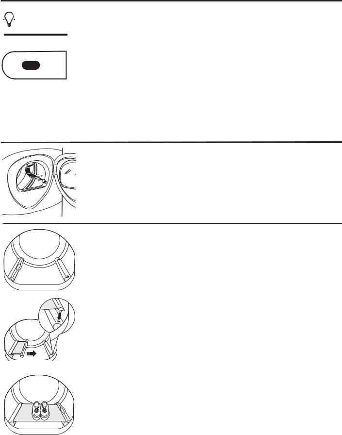
Built-In Rack Dry System
A handy drying rack may be used for drying items such as tennis shoes. Place items flat on the drying rack and block such items as wool sweaters and delicate fabrics. Dry with low heat.
To install the Built-In Rack Dry System
1. Make sure the drum of the dryer is oriented so the rack drying system is on the left side of the dryer.
2.Pull the drying rack screen out from the left side and engage the handle “posts” in the opposite baffle slots.
3. Place the garment on the rack and close the door. 4. Press the DRYER RACK button.
5. Select desired time.
6. Press the START/PAUSE button.
|
NOTE: |
|
Do not use this drying rack when there are other clothes in the dryer. |
Engage the handle posts |
Make sure to detach the drying rack at the end of the cycle and fully retract the screen back |
|
into the baffle. |
10
About dryer features (cont.). |
GEAppliances.com |
To Use the Built-In Hook for |
|
Hanging Garments |
|
1. Make sure the drum of the dryer is |
|
oriented so the hook is on the top |
|
center of the dryer. |
|
2. Using your finger, pull the hook out of the baffle.
3.Hang the garment on a hanger, hang the hanger on the hook and close the door.
4.Press the DRYER RACK button.
5.Select the desired time.
6.Press the START/PAUSE button.
Reverse Tumble™
All Profile front-load matching dryers are equipped with the Reverse Tumble™ feature, as part of the Duo Dry Plus system™. By reversing the direction of drum rotation during the drying cycle, your dryer will tangle the clothes load less, dry more evenly and improve drying times. Typical loads such as bed and bath mixed loads, where sheets, towels and pillow cases are laundered together, benefit from this capability. When the dryer reverses direction, there will be a slight pause and sound change. This is normal. All dryer cycles utilize this feature, except when the rack dry option is selected, in which case the drum does not tumble.
Using the dryer.
Always follow fabric manufacturer’s care label when laundering.
Sorting and Loading Hints
As a general rule, if clothes are sorted properly for the washer, they are sorted properly for the dryer. Try also to sort items according to size. For example, do not dry a sheet with socks or other small items.
Do not add fabric softener sheets once the load has become warm. They may cause fabric softener stains. Bounce® Fabric Conditioner Dryer Sheets have been approved for use in this dryer when used in accordance with the manufacturer’s instructions.
See below for lint filter cleaning instructions.
Do not overload. This wastes energy and causes wrinkling.
Do not dry the following items: fiberglass items,woolens,rubber-coateditems,plastics, items with plastic trim and foam-filled items.
11

Using the dryer.
Fabric Care Labels
Below are fabric care label “symbols” that affect the clothing you will be laundering.
Wash Labels
Machine wash
cycle |
|
|
|
|
|
|
|
|
Normal Permanent Press/ |
|
|
|
Hand wash Do not wash |
Do not wring |
|||
|
Gentle/ |
|
||||||
|
wrinkle resistant |
delicate |
|
|
||||
Front load target water temperature
|
|
Target |
Automatic |
|
|
Category |
Water Temperature |
Temperature Control |
|
|
|
|
|
|
|
Tap Cold |
Inlet Water Temperature |
Not used |
|
|
Cold |
27°C/80°F |
Used |
|
|
Warm |
40°C/105°F |
Used |
|
|
Hot |
50°C/120°F |
Used |
|
|
Sanitize |
70°C/160°F |
Used |
|
|
|
|
|
|
Dry Labels
Tumble dry
Dry |
Normal |
|
|
|
|
Do not dry |
|
|
|
|
|||
Permanent Press/ |
Gentle/ |
Do not tumble dry (used with |
||||
|
|
wrinkle resistant |
delicate |
do not wash) |
||
Heat setting
High |
Medium |
Low |
No heat/air |
Special instructions
Line dry/ |
Drip dry |
Dry flat |
In the shade |
hang to dry |
|
|
|
Bleach Labels
Bleach symbols
Any bleach |
Only non-chlorine bleach |
Do not bleach |
(when needed) |
(when needed) |
|
Care and Cleaning of the Dryer
Dryer Interior and Duct: The interior of the appliance and exhaust duct should be cleaned once a year by qualified service
personnel.
The Exterior: Wipe or dust any spills or washing compounds with a damp cloth. Dryer control panel and finishes may be damaged by some laundry pretreatment soil and stain remover products. Apply these products away from the dryer. The fabric may then be washed and dried normally. Damage to your dryer caused by these products is not covered by your warranty.
Do not touch the surface or the display with sharp objects.
The Lint Filter: Clean the lint filter before each use. Remove by pulling straight up. Run your fingers across the filter. A waxy buildup may form on the lint filter from
12 using dryer-added fabric softener sheets. To remove this buildup, wash the lint screen
in warm, soapy water. Dry thoroughly and replace. Do not operate the dryer without the lint filter in place.
Vacuum the lint from the dryer lint filter if you notice a change in dryer performance.
Stainless Steel: To clean stainless steel surfaces, use a damp cloth with a mild, nonabrasive cleaner suitable for stainless steel surfaces. Remove the cleaner residue, and then dry with a clean cloth.
The stainless steel used to make the dryer drum provides the highest reliability available in a GE dryer. If the dryer drum should be scratched or dented during normal use, the drum will not rust or corrode. These surface blemishes will not affect the function or durability of the drum.
The Exhaust Hood: Check with a mirror that the inside flaps of the hood move freely when operating. Make sure that there is no wildlife (birds, insects, etc.) nesting inside the duct or hood.
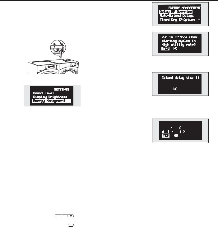
SMART APPLIANCE (on some models) |
GEAppliances.com |
|
Models PFDS450, PFDS455, PFDN440, PFDN445 are compatible with the |
Settings Menu |
|
GE Smart Appliance Module (SAM) which can be purchased separately. |
||
Press SETTINGS; then select |
||
Contact your local utility or visit www.GEAppliances.com/smart-appliances |
||
Energy Management. |
||
to see if your area is using Demand Response (DR) technology. |
||
|
||
Installation |
|
|
The preferred location for the module installation is on top of the clothes |
|
|
dryer. Details on how to connect the cables to the module are in the |
Delay EP Override |
|
instructions that come with the module. |
||
If you are starting a cycle in |
||
|
||
|
a Critical or High utility rate, |
|
|
this option allows the unit |
|
|
to automatically run on an |
|
|
EP Cycle. This setting will |
|
|
operate with less energy than normal cycles. Default setting is YES. |
Wait 5 minutes; then press the Settings button. Scroll and look for the energy management screen as seen below.
This screen means the module is attached correctly and you can begin to use your Smart Appliance following the instructions below.
If the Energy Management Screen is not available, refer to the SAM module troubleshooting guide.
Quick Guide There are 4 power levels available: Critical, High, Medium and Low. On the Medium and Low levels, the unit runs as normal. The following steps show how the unit reacts during startup at Critical and High power levels.
Option 1 (Delay EP) During startups at Critical and High levels, the unit will delay starting until the level becomes Medium or Low. Press the START/PAUSE button.
|
|
|
|
|
|
|
|
|
|
|
|
|
|
Option 2 (Override Delay EP) |
|
|
|
|
||
To start the unit when Delay EP is shown, press the DELAY START button to |
||||||
turn the delay off. Then press START/PAUSE to begin the cycle. |
||||||
During a Critical Rate period, the Critical Response Mode** will also be |
||||||
activated to maximize energy savings. EP will be displayed. |
||||||
|
|
e |
DELAY |
DRYER |
||
|
|
DRY |
START |
RACK |
||
BACK
ENTER
Option 3 (Override “e” DRY) After overriding the delay function, pressing the “e”DRY button will disable the “e”DRY setting. Pressing the START/PAUSE key will begin the selected cycle. During a Critical Rate period, the Critical Response Mode** will be activated to maximize energy savings. EP will be displayed. **Note: The Critical Response Mode can be disabled at any time by pressing and holding the “e”DRY Button for 3 seconds. EP will be removed from the display
Auto-Extend Delays If a timed delay is selected, 


 this option allows for the


 scheduled start to extend
  if the utility rate is Critical or High at the scheduled start. The default setting will automatically extend these cycles.
Critical Rate Option
This option allows your smart 


 appliance to respond to


 Critical Rate information by


 automatically engaging the Critical Response Mode. The Critical Response Mode is designed to maximize energy savings when a cycle is run during a Critical Rate period. The default setting is YES. Setting this option to NO will disable the Critical Response Mode.
Timed Dry EP Option 


 If the unit is running in Timed


 Dry Mode and the utility rate


 switches to Critical or High,

 the unit will conserve energy by decreasing heat if YES (default) is selected. If NO is selected, the unit will operate normally.
NOTE: When YES (default) is selected, your load may be damp at the end of the cycle.
In order for the Smart Appliance features on the appliance to work, additional equipment is required to be installed to interface with the local utility. Such equipment may be sold separately and/or is available through your utility as part of the pilot test program. Check with your utility company to see if a pilot test program is available in your area and for full details.
PLEASE NOTE: If you move to an area where the program is not available, the demand response features cannot be activated and utilized on the appliance. The appliance will function as normal after the demand response equipment has been deactivated or disconnected.
13
Installation |
Dryer |
Instructions |
PFMS450 / PFMS455 / PFMN440 / PFMN445 |
|
PFDS450 / PFDS455 /PFDN440 / PFDN445 / |
Questions? Call 800.GE.CARES (800.432.2737) or visit our Web site at: GEAppliances.com In Canada, call 1.800.561.3344 or visit www.GEAppliances.ca
BEFORE YOU BEGIN
Read these instructions completely and carefully.
• IMPORTANT – Save these instructions for local
electrical inspector’s use.
• IMPORTANT – Observe all governing codes and ordinances.
•Install the clothes dryer according to the manufacturer’s instructions and local codes.
•Note to Installer – Be sure to leave these instructions with the Consumer.
•Note to Consumer – Keep these instructions for future reference.
•Clothes dryer installation must be performed by a qualified installer.
•This dryer must be exhausted to the outdoors.
•Before the old dryer is removed from service or discarded, remove the dryer door.
•Service information and the wiring diagram are located in the control console.
•Do not allow children on or in the appliance. Close supervision of children is necessary when the appliance is used near children.
•Proper installation is the responsibility of the installer.
•Product failure due to improper installation is not covered under the Warranty.
•Install the dryer where the temperature is above 50°F for satisfactory operation of the dryer control system.
•Remove and discard existing plastic or metal foil duct and replace with UL-listed duct.
CALIFORNIA SAFE DRINKING WATER AND |
|
TOXIC ENFORCEMENT ACT |
|
This act requires the governor of California to publish a |
|
list of substances known to the state to cause cancer, |
|
birth defects or other reproductive harm and requires |
|
businesses to warn customers of potential exposure to such |
|
substances. Gas appliances can cause minor exposure to |
|
four of these substances, namely benzene, carbon monoxide, |
|
formaldehyde and soot, caused primarily by the incomplete |
|
combustion of natural gas or LP fuels. Properly adjusted |
|
dryers will minimize incomplete combustion. Exposure to |
|
these substances can be minimized further by properly |
|
venting the dryer to the outdoors. |
14 |
|
FOR YOUR SAFETY:
 WARNING – Risk of Fire
•To reduce the risk of severe injury or death, follow all installation instructions.
•Clothes dryer installation must be performed by a qualified installer.
•Install the clothes dryer according to these instructions and in accordance with local codes.
•This dryer must be exhausted to the outdoors.
•Use only rigid metal 4” diameter ductwork inside the dryer cabinet and use only UL approved transition ducting between the dryer and the home duct.
•DO NOT install a clothes dryer with flexible plastic ducting materials. If flexible metal (semi-rigid or foil-type) duct is installed, it must be UL-listed and installed in accordance with the instructions found in “Connecting the Dryer to House Vent” on page 26 of this manual. Flexible ducting materials are known to collapse, be easily crushed and trap lint. These conditions will obstruct dryer airflow and increase the risk of fire.
•Do not install or store this appliance in any location where it could be exposed to water and/or weather.
•Save these instructions. (Installers: Be sure to leave these instructions with the customer.)
FOR GAS MODELS ONLY:
NOTE: Installation and service of this dryer must be performed by a qualified installer, service agency or the gas supplier.
In the Commonwealth of Massachusetts:
•This product must be installed by a licensed plumber or gas fitter.
•When using ball-type gas shut-off valves, they shall be T-handle-type.
•A flexible gas connector, when used, must not exceed 3 feet.
Installation Instructions
UNPACKING YOUR DRYER
Tilt the dryer sideways and remove the foam shipping pads by pulling at the sides and breaking them away from the dryer legs. Be sure to remove all of the foam pieces around the legs.
Remove the bag containing the literature and serial cable.
LOCATION OF YOUR DRYER
MINIMUM CLEARANCE OTHER THAN ALCOVE OR CLOSET INSTALLATION
Minimum clearance to combustible surfaces and for air openings are:
•0 inch clearance both sides
•1 inch front
•3 inches rear
Consideration must be given to provide adequate clearance for proper operation and service.
DRYER DIMENSIONS
3939.1.″5”
Front View |
(993(100cm).3 cm) |
27”″ |
. |
(68.6 cm) |
53”1″
(134(129.6.5cm)
3939.1″.5”
(993(100cm).3 cm)
Side View
32.34 ″
(84733.cm)5”
(85.1 cm)
15
Installation Instructions
REQUIREMENTS FOR ALCOVE OR CLOSET INSTALLATION
•Your dryer is approved for installation in an alcove or closet, as stated on a label on the dryer back.
•The dryer MUST be vented to the outdoors. See the EXHAUSTING THE DRYER section.
•Minimum clearance between dryer cabinet and adjacent walls or other surfaces is:
0” either side
3” front and rear
•Minimum vertical space from floor to overhead shelves, cabinets, ceilings, etc., is 52”.
•Closet doors must be louvered or otherwise ventilated and have at least 60 square inches of open area equally distributed. If the closet contains both a washer and a dryer, doors must contain a minimum of 120 square inches of open area equally distributed.
•The closet should be vented to the outdoors to prevent gas pocketing in case of gas in the supply line.
•No other fuel-burning appliance shall be installed in the same closet with the dryer (gas models only).
NOTE: WHEN THE EXHAUST DUCT IS LOCATED AT THE REAR OF THE DRYER, MINIMUM CLEARANCE FROM THE WALL IS 5.5 INCHES.
BATHROOM OR BEDROOM INSTALLATION
•The dryer MUST be vented to the outdoors. See EXHAUSTING THE DRYER.
•The installation must conform with local codes or, in the absence of local codes, with the NATIONAL ELECTRICAL CODE, ANSI/NFPA NO. 70 (for electric dryers) or NATIONAL FUEL GAS CODE, ANSI Z223 (for gas dryers).
MOBILE OR MANUFACTURED HOME INSTALLATION
•The installation must conform to the MANUFACTURED HOME CONSTRUCTION & SAFETY STANDARD, TITLE 24, PART 32–80 or, when such standard is not applicable, with AMERICAN NATIONAL STANDARD FOR MOBILE HOME, NO. 501B.
•The dryer MUST be vented to the outdoors with the termination securely fastened to the mobile home structure. (See EXHAUSTING THE DRYER.)
•The vent MUST NOT be terminated beneath a mobile or manufactured home.
•The vent duct material MUST BE METAL.
•FOR GAS MODELS ONLY: KIT 14-D346-33 MUST be used to attach the dryer securely to the structure.
•FOR GAS MODELS ONLY: The vent MUST NOT be connected to any other duct, vent or chimney.
•Do not use sheet metal screws or other refastening devices which extend into the interior of the exhaust vent.
•Provide an opening with a free area of at least 25 sq. in. for introduction of outside air into the dryer room.
GARAGE INSTALLATION (IF ALLOWED BY LOCAL CODES)
•Dryers installed in garages must be elevated 18 inches (46cm) above the floor.
16
Installation Instructions
CONNECTING INLET HOSES
CONNECTING INLET HOSES
To produce steam, the dryer must connect to the cold water supply. Since the washer must also connect to the cold water, a “Y” connector is inserted to allow both inlet hoses to make that connection at the same time.
NOTE: Use the new inlet hoses provided; never use old hoses.
1. Turn the cold water faucet off. Remove the washer inlet hose from the washer fill valve connector (cold).
2. Ensure the rubber flat washer is in place and screw the female coupling of the short hose onto the washer fill valve connector. Tighten by hand until firmly seated.
3. Attach the female end of the ‘’Y’’ connector to the male coupling of the short hose. Ensure the rubber flat washer is in place. Tighten by hand until firmly seated.
4. Insert the filter screen in the coupling of the washer’s inlet hose. If a rubber flat washer is already in place remove it before installing the filter screen. Attach this coupling to one male end of the ‘’Y’’ connector. Tighten by hand until firmly seated.
5. Ensure the rubber flat washer is in place and attach the dryer’s long inlet hose to the other male end of the ‘’Y’’ connector. Tighten by hand until firmly seated.
6. Ensure the rubber flat washer is in place and attach the other end of the dryer’s long inlet hose to the fill valve connector at the bottom of the dryer back panel. Tighten by hand until firmly seated.
CONNECTING INLET HOSES (cont.)
7. Using pliers, tighten all the couplings with an additional two–thirds turn.
NOTE: Do not overtighten. Damage to the couplings may result.
8. Turn the water faucet on.
9. Check for leaks around the ‘’Y’’ connector, faucet and hose couplings.
WATER SUPPLY REQUIREMENTS
Hot and cold water faucets MUST be installed within 42 in. (107 cm) of your washer’s water inlet. The faucets MUST be 3/4 in. (1.9 cm) garden hose-type so inlet hoses can be connected. Water pressure MUST be between 10 and 120 pounds per square inch. Your water department can advise you of your water pressure.
NOTE: A water softener is recommended to reduce buildup of scale inside the steam generator if the home water supply is very hard.
17

Installation Instructions
CONNECTING A GAS DRYER (skip for electric dryers)
TOOLS YOU WILL NEED
10” Adjustable |
Flat-blade |
wrenches (2) |
screwdriver |
|
Level |
8” Pipe wrench
Slip-joint pliers
MATERIALS YOU WILL NEED
4” dia. metal elbow
Pipe compound
Flexible gas line connector
Duct clamps (2) or Spring clamps (2)
Safety glasses
4” dia. metal duct (recommended)
4” dia., UL-listed flexible metal duct (if needed)
Gloves
Soap solution for leak detection
Exhaust hood
Duct tape
FOR YOUR SAFETY:
 WARNING
Before beginning the installation, turn off the circuit breaker(s) or remove the dryer’s circuit fuse(s) at the electrical box. Be sure the dryer cord is unplugged from the wall.
Turn the dryer’s gas shut-off valve in the supply line to the OFF position.
Shut-off
Valve
Disconnect and discard old flexible gas connector and ducting material.
18

Installation Instructions
GAS REQUIREMENTS
 WARNING
•Installation must conform to local codes and ordinances, or in their absence, with the National Fuel Gas Code, ANSI Z223.1/NFPA 54, or the Natural Gas and Propane Installation Code, CSA B149.1.
•This gas dryer is equipped with a Valve and Burner Assembly for use only with natural gas. Using conversion kit 14-A048, your local service organization can convert this dryer for use with propane (LP) gas. ALL CONVERSIONS MUST BE MADE BY PROPERLY TRAINED AND QUALIFIED PERSONNEL AND IN ACCORDANCE WITH LOCAL CODES AND ORDINANCE REQUIREMENTS.
•The dryer must be disconnected from the gas supply piping system during any pressure testing of that system at a test pressure in excess of 0.5 PSI (3.4 KPa).
•The dryer must be isolated from the gas supply piping system by closing the equipment shut-off valve during any pressure testing of the gas supply piping of test pressure equal to or less than 0.5 PSI (3.4KPa).
DRYER GAS SUPPLY CONNECTION
2” (5.1 cm)
3/8” NPT MALE THREAD GAS SUPPLY
25ø8” (6.7 cm) NOTE: Add to vertical dimension the distance between cabinet bottom to floor.
You must use with this dryer a flexible metal connector (listed connector ANSI Z21.24 / CSA 6.10). The length of the connect shall not exceed 3 ft.
GAS SUPPLY
•A 1/8” National Pipe Taper thread plugged tapping, accessible for test gauge connection, must be installed immediately upstream of the gas supply connection to the dryer. Contact your local gas utility should you have questions on the installation of the plugged tapping.
•Supply line is to be 1/2” rigid pipe and equipped with an accessible shutoff within 6 feet of, and in the same room with, the dryer.
•Use pipe thread compound appropriate for natural or LP gas or use Teflon® tape.
•Connect flexible metal connector to dryer and gas supply.
IN THE COMMONWEALTH OF
MASSACHUSETTS
•This product must be installed by a licensed plumber or gas fitter.
•When using ball-type gas shut-off valves, they shall be the T-handle type.
•A flexible gas connector, when used, must not exceed 3 feet.
ADJUSTING FOR ELEVATION
•Gas clothes dryers input ratings are based on sea level operation and need not be adjusted for operation at or below 2000 ft. elevation. For operation at elevations above 2000 ft., input ratings should be reduced at a rate of 4 percent for each 1000 ft. above sea level.
•Installation must conform to local codes and ordinances or, in their absence, with the National Fuel Gas Code, ANSI Z223.1/NFPA 54, or the Natural Gas and Propane Installation Code, CSA B149.1
19
Installation Instructions
CONNECTING A GAS DRYER (cont.)
CONNECTING THE DRYER TO THE GAS SUPPLY
AInstall a female 3/8” NPT elbow at the end of the dryer gas inlet.
Install a 3/8” flare union adapter to the female elbow.
IMPORTANT: Use a pipe wrench to securely hold on to the end of the dryer gas inlet to prevent twisting the inlet.
NOTE: Apply pipe compound or Teflon® tape to the threads of the adapter and dryer gas inlet.
New Metal |
|
Adapter |
Flexible Gas |
|
1/8” NPT |
Line Connector |
|
|
Adapter |
|
Pipe Plug for |
|
Checking Gas |
|
Elbow |
3/8” NPT |
Inlet Pressure |
|
Shut-Off Valve |
|
Items not supplied |
|
|
|
Pipe size at |
|
|
|
|
|
|
least 1/2” |
BAttach the flexible metal gas line connector to the adapter.
Apply pipe compound to the adapter and dryer gas inlet.
CTighten the flexible gas line connection, using two adjustable wrenches.
CONNECTING THE DRYER TO THE GAS
SUPPLY (cont.)
DInstall a 1/8” NPT plugged tapping to the dryer gas line shut-off valve for checking gas inlet pressure.
Install a flare union adapter to the plugged tapping.
NOTE: Apply pipe compound or Teflon® tape to the threads of the adapter and plugged tapping.
Apply pipe compound |
Plugged |
or Teflon® tape to all |
|
male threads. |
Tapping |
Shut-Off
Valve
ETighten all connections, using two adjustable wrenches. Do not overtighten.
F Open the gas shut-off valve.
20
Installation Instructions
TEST FOR LEAKS
 WARNING – Never use an open flame to test for gas leaks.
Check all connections for leaks with soapy solution or equivalent.
Apply a soap solution. The leak test solution must not contain ammonia, which could cause damage to the brass fittings.
If leaks are found, close the valve, retighten the joint and repeat the soap test.
Open Gas
Valve
ELECTRICAL CONNECTION INFORMATION FOR GAS DRYERS
 WARNING – To reduce the risk of fire, electrical shock and personal injury:
•Do not use an extension cord or an adapter plug with this appliance.
•The dryer must be electrically grounded in accordance with local codes and ordinances, or in the absence of local codes, in accordance with the NATIONAL ELECTRICAL CODE, ANSI/NFPA NO. 70 or Canadian Electrical Code, CSA C22.1
ELECTRICAL REQUIREMENTS FOR GAS DRYERS
This appliance must be supplied with 120V, 60Hz, and connected to a properly grounded branch circuit, protected by a 15or 20-amp circuit breaker or time-delay fuse.
If electrical supply provided does not meet the above specifications, it is recommended that a licensed electrician install an approved outlet.
 WARNING – This dryer is equipped with a three-prong (grounding) plug for your protection against shock hazard and should be plugged directly into a properly grounded three-prong receptacle. Do not cut or remove the grounding terminal from this plug.
Ensure proper ground exists before use.
If local codes permit, an external ground wire (not provided), which meets local codes, may be added by attaching to the green ground screw on the rear of the dryer, and to an alternate established ground.
Ensure proper ground exists before use.
Ground
Screw
21
Installation Instructions
CONNECTING AN ELECTRIC DRYER (skip for gas dryers)
TOOLS YOU WILL NEED
|
|
|
|
|
|
|
|
|
|
|
|
|
|
|
|
|
|
|
|
|
|
|
|
|
|
|
|
|
|
|
|
|
|
Phillips screwdriver |
|||||||||||||
|
Slip-joint pliers |
|
|||||||||||||
|
|
|
|
|
|
|
|
|
|
|
|
|
|
|
|
|
|
|
|
|
|
|
|
|
|
|
|
|
|
|
|
|
|
|
|
|
|
|
|
|
|
|
|
|
|
|
|
|
|
|
|
|
|
|
|
|
|
|
|
|
|
|
|
|
|
|
|
|
|
|
|
|
|
|
|
|
|
|
|
|
|
|
|
|
|
|
|
|
|
|
|
|
|
|
|
|
|
|
|
|
|
|
|
|
|
|
|
|
|
|
|
|
|
|
|
|
|
|
|
|
|
|
|
|
|
|
|
Flat-blade crewdriver |
Level |
MATERIALS YOU WILL NEED
4” dia. metal elbow
3/4” strain relief (UL recognized)
4” duct clamps (2) or 4” spring clamps (2)
Safety glasses
4” dia. metal duct (recommended)
4” dia., UL-listed flexible metal duct (if needed)
Gloves
Exhaust hood
Duct tape
Dryer power cord kit (not provided with dryer)
UL rated 120/240V, 30A with 3 or 4 prongs. Identify the plug type as per the house receptacle before purchasing line cord.
FOR YOUR SAFETY:
 WARNING
Before making the electrical connection, turn off the circuit breaker(s) or remove the dryer’s circuit fuse(s) at the electrical box. Be sure the dryer cord
is unplugged from the wall. NEVER LEAVE THE ACCESS COVER OFF THE TERMINAL BLOCK.
ELECTRICAL CONNECTION INFORMATION FOR ELECTRIC DRYERS
 WARNING – To reduce the risk of fire, electrical shock and personal injury:
•Do not use an extension cord or an adapter plug with this appliance.
•The dryer must be electrically grounded in accordance with local codes, or in the absence of local codes, with the National Electrical Code, ANSI/NFPA NO. 70 or Canadian Electrical Code, CSA C22.1.
22
Installation Instructions
ELECTRICAL REQUIREMENTS FOR ELECTRIC DRYERS
This dryer must be connected to an individual branch circuit, protected by the required time-delay fuses or circuit breakers. A threeor four-wire, single-phase, 120/240V or 120/208V, 60Hz, 30-amp circuit is required.
If the electric supply does not meet the above specifications, then call a licensed electrician.
ELECTRICAL REQUIREMENTS FOR ELECTRIC DRYERS (CANADA)
This dryer must be connected to an individual branch circuit, protected by the required time-delay fuses or circuit breakers. The power supply must be of 120/240 volts, 60Hz circuit with the wall receptacle as shown below.
 G
G
YX
W
TYPICAL 30 AMP
RECEPTACLE FOR DRYER
The power supply must be protected with 30 Amp fuses or breakers. It must be well grounded and conform to local codes.
GROUNDING INSTRUCTIONS
This dryer must be connected to a grounded metal, permanent wiring system, or an equipmentgrounding conductor must be run with the circuit conductors and connected to the equipment grounding terminal on the appliance.
GROUNDING INSTRUCTIONS (CANADA)
This appliance must be grounded. In the event of malfunction or breakdown, grounding will reduce the risk of electrical shock by providing a path of least resistance for electrical current. This appliance is equipped with a cord having an equipment-grounding conductor and a grounding plug. The plug must be plugged into an appropriate outlet that is properly installed and grounded in accordance with all local codes and ordinances.
CONNECTING DRYER USING 4-WIRE CONNECTION (MUST BE USED FOR MOBILE HOME INSTALLATION)
NOTE: Since January 1, 1996, the National Electrical Code requires that new constructions utilize a 4-wire connection to an electric dryer. A 4-wire cord must also be used where local codes do not permit grounding through the neutral.
3-wire connection is NOT for use on new construction.
|
|
|
|
Relocatre |
|
||
|
|
Green |
green ground |
4 #10 AWG |
|||
Hot Wire |
screw here |
||||||
Screw Wire |
|||||||
|
|
|
|
|
|
minimum |
|
|
Screw |
|
|
|
|
copper |
|
Remove |
|
|
|
|
conductors |
||
ground strap |
|
|
|
|
or 120/240V |
||
and discard. |
|
|
|
|
30A power |
||
Keep green |
|
|
|
|
supply cord kit |
||
ground |
Neutral |
|
|
|
|
marked for use |
|
screw. |
(white) |
|
|
|
|
with dryers |
|
|
Hot Wire |
|
|
Strain |
and provided |
||
|
|
|
with closed |
||||
|
3/4” UL |
Relief |
|||||
|
|
Screw |
loop or spade |
||||
|
|
Recognized |
Bracket |
||||
|
|
|
Strain Relief |
|
terminals with |
||
|
|
|
|
upturned ends |
|||
(not supplied)
1.Turn off the circuit breaker(s) (30 amp) or remove the dryer’s circuit fuse at the electrical box.
2.Be sure the dryer cord is unplugged from the wall receptacle.
3.Remove the power cord cover located at the lower back.
4.Remove and discard ground strap. Keep the green ground screw for Step 7.
5.Install 3/4 in. UL-recognized strain relief to power cord entry hole. Bring power cord through strain relief.
6.Connect power cord as follows:
A.Connect the 2 hot lines to the outer screws of the terminal block (marked L1 and L2).
B.Connect the neutral (white) line to the center of the terminal block (marked N).
7.Attach ground wire of power cord with the green ground screw (hole above strain relief bracket). Tighten all terminal block screws (3) securely.
8.Properly secure power cord to strain relief.
9.Reinstall the cover.
 WARNING – NEVER LEAVE THE COVER OFF OF THE TERMINAL BLOCK.
23
Installation Instructions
CONNECTING AN ELECTRIC DRYER (cont.)
CONNECTING DRYER USING 3-WIRE CONNECTION
If required, by local code, install external ground (not provided) to grounded metal, cold water pipe, or other established ground determined by a qualified electrician.
|
Hot Wire |
Screw |
|
3 #10 AWG |
|
Screw |
|
|
|
minimum |
|
Ground |
|
|
|
copper |
|
|
|
|
conductors or |
||
Strap |
|
|
|
||
|
|
|
120/240V 30A |
||
|
|
|
|
||
Green |
|
|
|
power supply |
|
ground |
|
|
|
cord kit marked |
|
screw |
|
|
|
for use with |
|
Neutral |
|
|
|
dryers and |
|
(white) |
|
3/4” UL |
Strain |
provided with |
|
Hot Wire |
Screw |
closed loop or |
|||
Recognized |
Relief |
spade terminals |
|||
|
|
||||
|
|
Strain Relief |
Bracket |
with upturned |
ends (not supplied)
3-wire Connection
Not for use in Canada.
DO NOT use for Mobile Home Installations. NOT for use on new construction.
NOT for use on recreational vehicles.
NOT for use in areas where local codes prohibit grounding through the neutral conduction.
CONNECTING DRYER USING 3-WIRE
CONNECTION (cont.)
1.Turn off the circuit breaker(s) (30 amp) or remove the dryer’s circuit fuse at the electrical box.
2. Be sure the dryer cord is unplugged from the wall receptacle.
3.Remove the power cord cover located at the lower back.
4.Install 3/4-in. UL-recognized strain relief to power cord entry hole. Bring power cord through strain relief.
5.Connect power cord as follows:
A.Connect the 2 hot lines to the outer screws of the terminal block (marked L1 and L2).
B.Connect the neutral (white) line to the center of the terminal block (marked N).
6. Be sure ground strap is connected to neutral (center) terminal of block and to green ground screw on cabinet rear. Tighten all terminal block screws (3) securely.
7.Properly secure power cord to strain relief.
8.Reinstall the cover.
 WARNING – NEVER LEAVE THE COVER OFF OF THE TERMINAL BLOCK.
24
Installation Instructions
EXHAUSTING THE DRYER
 WARNING – To reduce the risk of fire or personal injury:
•This clothes dryer must be exhausted to the outdoors.
•Use only 4” rigid metal ducting for the home exhaust duct.
•Use only 4” rigid metal or UL-listed flexible metal (semi-rigid or foil-type) duct to connect the dryer to the home exhaust duct. It must be installed in accordance with the instructions found in “Connecting the Dryer to House Vent” on page 26 of this manual.
•Do not terminate exhaust in a chimney, a wall, a ceiling, gas vent, crawl space, attic, under an enclosed floor, or in any other concealed space of a building. The accumulated lint could cause a potential fire hazard.
•Never terminate the exhaust into a common duct with a kitchen exhaust system. A combination of grease and lint creates a potential fire hazard.
•Do not use duct longer than specified in the exhaust length table. Longer ducts can accumulate lint, creating a potential fire hazard.
•Never install a screen in or over the exhaust duct. This will cause lint to accumulate, creating a potential fire hazard.
•Do not assemble ductwork with any fasteners that extend into the duct. These fasteners can accumulate lint, creating a potential fire hazard.
•Do not obstruct incoming or exhausted air.
•Provide an access for inspection and cleaning of the exhaust system, especially at turns and joints. Exhaust system shall be inspected and cleaned at least once a year.
•This dryer comes ready for rear exhausting. If space is limited, use the instructions on pages 29–31 to exhaust directly from the sides or bottom of the cabinet.
EXHAUST SYSTEM CHECKLIST
HOOD OR WALL CAP
•Terminate in a manner to prevent back drafts or entry of birds or other wildlife.
•Termination should present minimal resistance to the exhaust airflow and should require little or no maintenance to prevent clogging.
•Never install a screen in or over the exhaust duct.
•Wall caps must be installed at least 12” above ground level or any other obstruction with the opening pointed down.
SEPARATION OF TURNS
•For best performance, separate all turns by at least 4 ft. of straight duct, including distance between last turn and dampened wall cap.
SEALING OF JOINTS
•All joints should be tight to avoid leaks. The male end of each section of duct must point away from the dryer.
•Do not assemble the ductwork with fasteners that extend into the duct. They will serve as a collection point for lint.
•Duct joints should be made airand moisture-tight by wrapping the overlapped joints with duct tape or aluminum tape.
•Horizontal runs should slope down towards the outdoors 1/4” per foot.
INSULATION
•Ductwork that runs through an unheated area or is near air conditioning should be insulated to reduce condensation and lint buildup.
TOOLS AND MATERIALS YOU WILL NEED TO INSTALL EXHAUST DUCT
Phillips-head screwdriver
Rigid or UL-listed flexible metal 4” (10.2 cm) duct
Duct tape or duct clamp
Drill with 1/8” drill bit
(for bottom venting) |
Vent hood |
|
|
Hacksaw |
|
25
Installation Instructions
EXHAUSTING THE DRYER (cont.)
CONNECTING THE DRYER TO HOUSE VENT
RIGID METAL TRANSITION DUCT
•For best drying performance, a rigid metal transition duct is recommended.
•Rigid metal transition ducts reduce the risk of crushing and kinking.
UL-LISTED FLEXIBLE METAL (SEMI-RIGID) TRANSITION DUCT
•If rigid metal duct cannot be used, then UL-listed flexible metal (semi-rigid) ducting can be used (Kit WX08X10077).
•Never install flexible metal duct in walls, ceilings, floors or other enclosed spaces.
•Total length of flexible metal duct should not exceed 8 feet (2.4 m).
•For many applications, installing elbows at both the dryer and the wall is highly recommended (see illustrations at right). Elbows allow the dryer to sit close to the wall without kinking and/or crushing the transition duct, maximizing drying performance.
•Avoid resting the duct on sharp objects.
UL-LISTED FLEXIBLE METAL (FOIL-TYPE) TRANSITION DUCT
•In special installations, it may be necessary to connect the dryer to the house vent using a flexible metal (foil-type) duct. A UL-listed flexible metal (foil-type) duct may be used ONLY in installations where rigid metal or flexible metal (semi-rigid) ducting cannot be used AND where a 4” diameter can be maintained throughout the entire length of the transition duct.
•In Canada and the United States, only the flexible metal (foil-type) ducts that comply with the “Outline for Clothes Dryer Transition Duct Subject 2158A” shall be used.
•Never install flexible metal duct in walls, ceilings, floors or other enclosed spaces.
•Total length of flexible metal duct should not exceed 8 feet (2.4 m).
•Avoid resting the duct on sharp objects.
•For best drying performance:
1.Slide one end of the duct over the clothes dryer outlet pipe.
2.Secure the duct with a clamp.
3.With the dryer in its permanent position, extend the duct to its full length. Allow 2” of duct to overlap the exhaust pipe. Cut off and remove excess duct. Keep the duct as straight as possible for maximum airflow.
4.Secure the duct to the exhaust pipe with the other clamp.
FOR TRANSITION VENTING (DRYER TO WALL), DO:
•DO cut duct as short as possible and install straight into wall.
•DO use elbows when turns are necessary.
Elbows
DO NOT:
•DO NOT bend or collapse ducting. Use elbows
if turns are necessary.
•DO NOT use excessive exhaust length. Cut duct as short as possible.
•DO NOT crush duct against the wall.
•DO NOT set dryer on duct.
26
Installation Instructions
 WARNING – USE ONLY METAL 4” DUCT. DO NOT USE DUCT LONGER THAN SPECIFIED IN THE EXHAUST LENGTH TABLE.
Using exhaust longer than specified length will:
•Increase the drying times and the energy cost.
•Reduce the dryer life.
•Accumulate lint, creating a potential fire hazard.
The correct exhaust installation is YOUR RESPONSIBILITY.
Problems due to incorrect installation are not covered by the warranty.
The MAXIMUM ALLOWABLE length of the exhaust system depends upon the type of duct, number of turns, the type of exhaust hood (wall cap) and all conditions noted below.
EXHAUST LENGTH
RECOMMENDED MAXIMUM LENGTH
Exhaust Hood Types
Recommended |
Use only for short-run |
|
installations |
4” DIA |
4” DIA |
|
|
4” DIA |
|
|
4” |
21ø2” |
|
|
|
No. of 90º |
Rigid |
Rigid |
Elbows |
Metal |
Metal |
0 |
150 Feet |
125 Feet |
1 |
135 Feet |
115 Feet |
2 |
125 Feet |
105 Feet |
3 |
115 Feet |
95 Feet |
4 |
105 Feet |
85 Feet |
5 |
95 Feet |
75 Feet |
•For every extra 90° elbow, reduce the allowable vent system length by 10 ft.
•Two 45° elbows will be treated like one 90° elbow.
•For the side exhaust installations, add one 90° elbow to the chart.
•The total vent system length includes all the straight portions and elbows of the system (transition duct included).
27
EXHAUST SYSTEM CHECKLIST
HOOD OR WALL CAP
•Terminate in a manner to prevent back drafts or entry of birds or other wildlife.
•Termination should present minimal resistance to the exhaust airflow and should require little or no maintenance to prevent clogging.
•Never install a screen in or over the exhaust duct. This could cause lint buildup.
•Wall caps must be installed at least 12” above ground level or any other obstruction with the opening pointed down.
SEPARATION OF TURNS
For best performance, separate all turns by at least 4 ft. of straight duct, including the distance between the last turn and the exhaust hood.
TURNS OTHER THAN 90º
•One turn of 45º or less may be ignored.
•Two 45º turns should be treated as one 90º turn.
•Each turn over 45º should be treated as one 90º turn.
SEALING OF JOINTS
•All joints should be tight to avoid leaks. The male end of each section of duct must point away from the dryer.
•Do not assemble the ductwork with fasteners that extend into the duct. They will serve as a collection point for lint.
•Duct joints can be made airand moisture-tight by wrapping the overlapped joints with duct tape.
•Horizontal runs should slope down toward the outdoors 1/4” per foot.
INSULATION
Ductwork that runs through an unheated area or is near air conditioning should be insulated to reduce condensation and lint buildup.
Installation Instructions
EXHAUSTING THE DRYER (cont.)
BEFORE YOU BEGIN
•Remove and discard existing plastic or metal foil duct and replace with UL-listed duct.
•Remove any lint from the wall exhaust opening.
Wall
Internal
Duct
Opening
 Check that exhaust
hood damper opens
and closes freely.
STANDARD REAR EXHAUST
We recommend that you install your dryer before installing your washer. This will permit direct access for easier exhaust connection.
Slide the end of the exhaust duct on the back of the dryer and secure with duct tape or a hose clamp.
RECOMMENDED CONFIGURATION TO MINIMIZE EXHAUST BLOCKAGE
Using duct elbows will prevent duct kinking and collapsing.
Transition
Ducting
Duct
NOTE: We strongly recommend using rigid metal exhaust duct.
•For straight-line installation, connect the dryer exhaust to the wall, using duct tape.
Wall Side
Dryer
Side
28
Installation Instructions
SIDE VENTING:
Dryer Exhaust to right of cabinet for Electric models only.
Dryer Exhaust to left of cabinet for Gas and Electric models.
 WARNING–BEFOREPERFORMING THIS EXHAUST INSTALLATION, BE SURE TO DISCONNECT THE DRYER FROM ITS ELECTRICAL SUPPLY. PROTECT YOUR HANDS AND ARMS FROM SHARP EDGES WHEN WORKING INSIDE THE CABINET. BE SURE TO WEAR GLOVES.
Remove Right screw  and save
Left
Bottom
Remove desired knockout (one only)
Detach and remove the bottom, right or left side knockout as desired. Remove the screw inside the dryer exhaust duct and save. Pull the duct out of the dryer.
Fixing hole
A
13 1ø2”
Cut the duct as shown and keep portion A.
TAB LOCATION
Not for gas
Bend tab up 45°
Through the rear opening, locate the tab in the middle of the appliance base. Lift the tab to about
45°, using a flat-blade screwdriver.
29
ADDING A NEW DUCT
Fixing hole |
Portion “A” |
Left side  exhaust
Reconnect the cut portion (A) of the duct to the blower housing. Make sure that the shortened duct is aligned with the tab in the base. Use the screw saved previously to secure the duct in place through the tab on the appliance base.
ADDING ELBOW AND DUCT FOR EXHAUST TO LEFT OR RIGHT SIDE OF CABINET
Internal duct
Rear opening

 Side opening
•Insert the 4” elbow through the rear opening and connect the elbow to the dryer internal duct.
•Insert the 4” duct through the side opening and connect it to the elbow.
 CAUTION: Do not pull or damage the electrical wires and do not remove the vinyl cover from the electrical components inside the dryer when inserting the duct. A slight interference may occur between the exhaust and the wire components.
Installation Instructions
EXHAUSTING THE DRYER (cont.)
SIDE VENTING (cont.)
ADDING ELBOW AND DUCT FOR EXHAUST TO LEFT OR RIGHT SIDE OF CABINET (cont.)
• Apply |
duct |
tape as |
Duct tape |
|
shown |
on |
the |
joint |
|
between the |
dryer |
|
||
internal duct and the |
|
|||
elbow, |
and |
also the |
|
|
joint |
between |
the |
|
|
elbow |
and |
the |
side |
|
duct. |
|
|
|
|
 CAUTION: Use 4” rigid metal ducting only inside the dryer. Internal duct joints must be secured with tape, otherwise they may separate and cause a safety hazard.
ADDING COVER PLATE TO REAR OF CABINET (SIDE EXHAUST)
Plate

(Kit WE1M454)
Connect standard metal elbows and ducts to complete the exhaust system. Cover back opening with a plate (Kit WE1M454) available from your local service provider. Place dryer in final location.
 WARNING – NEVER LEAVE THE BACK OPENING WITHOUT THE PLATE. (Kit
WE1M454)
BOTTOM VENTING:
Dryer Exhaust to the bottom of cabinet for Gas and Electric models.
 WARNING – BEFORE PERFORMING THIS EXHAUST INSTALLATION, BE SURE TO DISCONNECT THE DRYER FROM ITS ELECTRICAL SUPPLY. PROTECT YOUR HANDS AND ARMS FROM SHARP EDGES WHEN WORKING INSIDE THE CABINET. BE SURE TO WEAR GLOVES.
Remove screw and save
Bottom
Remove desired knockout (one only)
Remove the screw inside the dryer exhaust duct and save. Pull the duct out of the dryer. Detach and remove the bottom knockout.
Fixing hole
A
13 1ø4”
Cut the duct as shown and keep portion A.
30
 Loading...