


 Loading...
EPM 5200, 5300, 5350
DIGITAL MULTIFUNCTION POWER MONITORS
Instruction Manual
GEK-106557A
Copyright © 2004 GE Multilin
g
|
GE Industrial Systems |
|
|
|
|
NORTH AMERICA |
EUROPE |
|
215 Anderson Avenue, Markham, Ontario, L6E 1B3 Canada |
Avenida Pinoa 10 – 48710, Zamudio (Vizcaya) Spain |
|
Tel: (905) 294-6222 Fax: (905) 201-2098 |
Tel: +34 94 485 88 00 Fax: +34 94 485 88 45 |
|
E-mail: info.pm@indsys.ge.com |
|
|
Internet: http://www.GEindustrial.com/multilin |
|
|

TABLE OF CONTENTS
CHAPTER 1: AC POWER |
|
MEASUREMENT ............. |
1 |
1.1: Single Phase System................ |
1 |
1.2: Three-Phase System ................ |
2 |
1.3: Consumption, Demand and |
|
Poor Power Factor.................... |
3 |
1.4: Waveform and Harmonics ........ |
4 |
CHAPTER 2: MECHANICAL |
|
INSTALLATION ............... |
5 |
CHAPTER 3: ELECTRICAL |
|
INSTALLATION ............... |
7 |
3.1: Current Circuit........................... |
7 |
3.2: CT Connection.......................... |
7 |
3.3: Voltage Circuit........................... |
8 |
3.4: Selecting the Voltage Fuses ..... |
8 |
3.5: Connection to the Main Power |
|
Supply ....................................... |
8 |
3.6: Electrical Connection |
|
Installation................................. |
8 |
3.7: Relay, Protection and Pulse |
|
Output ....................................... |
14 |
3.8: KYZ Pulse Outputs: NL2 |
|
Option ....................................... |
15 |
CHAPTER 4: COMMUNICATION |
|
INSTALLATION ............... |
17 |
4:1: RS-232C ................................... |
17 |
4.2: RS-485...................................... |
17 |
4.3: Network and Long Distance |
|
Communication......................... |
20 |
CHAPTER 5: OVERVIEW ......................... |
23 |
5.1: Accessing the Power |
|
Functions .................................. |
24 |
5.2: Accessing Voltage and |
|
Current Phases......................... |
24 |
5.3: Accessing %THD Functions ..... |
24 |
5.4: Viewing Individual Phase |
|
Indication for Power |
|
Functions ................................. |
25 |
5.5: Accessing Max/Min Values....... |
26 |
5.6: Resetting Values....................... |
26 |
5.7: Resetting Hour Readings.......... |
28 |
5.8: Accessing the LM1/LM2 |
|
Set Limits.................................. |
28 |
5.9: Voltage Phase Reversal and |
|
Imbalance ................................ |
29 |
5.10: Access Modes ........................ |
30 |
5:11: Print Operating Data............... |
30 |
5.12: Print Programming Data......... |
31 |
5.13: Accessing Firmware |
|
Version/LED Test ................... |
31 |
CHAPTER 6: OVERVIEW......................... |
33 |
6.1 General Procedure .................... |
33 |
6.2: Switch Packs ............................ |
33 |
6.3: Data Entry................................. |
34 |
6.4: Standard Numeric Data Entry... |
34 |
CHAPTER 7: EPM 5200P...................... |
35 |
CHAPTER 8: ENTERING THE |
|
PROGRAMMING MODE ... |
37 |
8.1: Checksum Error—Protective |
|
Self-Checking Algorithms ......... |
37 |
8.2: Password Entry ........................ |
37 |
CHAPTER 9: PROGRAMMING GROUP 0: |
|
GLOBAL METER SETUP . 39 |
|
9.1: Group 0, Function 0 |
|
The Integration Interval............. |
39 |
9.2: Group 0, Function 1— |
|
The Meter Address ................... |
40 |
9.3: Group 0, Function 2— |
|
BAUD RATE ............................. |
41 |
9.4: Group 0, Function 3— |
|
System Configuration .............. |
42 |
9.5: Modbus Plus Capability............ |
44 |
9.6: Group 0, Function 3— |
|
Programming Procedure .......... |
45 |
9.7: Relay Mode .............................. |
46 |
9.8: Group 0, Functions 4–5—Time |
|
Delay for Relays 1 and 2 |
|
(Option – NL) ............................ |
49 |
9.9: Group 0, Function 6—KYZ |
|
Parameter Selection ................ |
51 |
9.10: Group 0, Function 7— |
|
Number of Phases.................... |
54 |
GE Multilin |
EPM 5000 series Advanced Power Meters |
iii |

CHAPTER 10: PROGRAMMING GROUP 1: |
|
VOLTAGE, AMP AND WATT |
|
SCALE SETTINGS......... |
55 |
10.1: Group 1, Function 0—Full |
|
Scale Voltage Settings, Scale |
|
Factor & Decimal Point |
|
Placement ............................... |
55 |
10.2: Group 1, Function 1— |
|
Amperage Full Scale............... |
58 |
10.3: Group 1, Function 2—Scale |
|
Selection and Decimal |
|
Placement for Watts................ |
59 |
CHAPTER 11: PROGRAMMING GROUP 2: |
|
METER CALIBRATION ....... |
63 |
11.1: Calibration Requirements ....... |
63 |
11.2: Group 2, Functions 0–8— |
|
High End Calibration of Voltage |
|
Channels, High and Low End |
|
Calibration of Amperage |
|
Channels................................. |
64 |
CHAPTER 12: GROUPS 4, 5 AND 6: SET |
|
LIMITS AND RELAYS ... |
67 |
12.1: Trip Relay................................ |
67 |
12.2: Time Delays & Relay Mode .... |
67 |
12.3: Group 4, Functions 0–3— |
|
LM1/LM2 Set Limits ................ |
68 |
12.4: Group 5, Functions 0–7— |
|
LM1/LM2 Set Limits ................ |
69 |
12.5: Group 6, Functions 0–5— |
|
LM1/LM2 Set Limits and |
|
Relay Triggers for Over/Under |
|
%THD Conditions ................... |
72 |
12.6: Limits or Relays Programming |
|
Procedure ............................... |
72 |
CHAPTER 13: PHASE REVERSAL |
|
AND PHASE IMBALANCE |
|
SET LIMITS/RELAYS.......... |
75 |
13.1: Phase Reversal and Phase |
|
Imbalance ............................... |
75 |
13.2: Trip Relay................................ |
75 |
13.3: Group 7, Function 0—Voltage |
|
Phase Reversal Detection ...... |
76 |
13.4: Group 7, Function 1— |
|
Percentage Voltage Phase |
|
Imbalance ............................... |
77 |
CHAPTER 14: EXITING THE PROGRAMMING |
|
MODE ............................. |
79 |
CHAPTER 15: PROGRAMMING QUICK |
|
REFERENCE………………81 |
|
15.1: Entering the Programming |
|
Mode ...................................... |
81 |
15.2: Data Entry Sequence ............. |
81 |
15.3: Programming Groups ............. |
81 |
15.4: Group 0: Global Setup............ |
82 |
15.5: Group 1: Full Scale Setup ...... |
83 |
15.6: Group 2 Calibration ................ |
83 |
15.7: Group 3 Calibration Ratios ..... |
83 |
15.8: Group 4: Volt/Current Limits... |
83 |
15.9: Group 5: Power Function Limits |
|
......................................................... |
84 |
15.10: Group 6: THD Limits............. |
84 |
15.11: Group 7 Imbalance/Reversal |
|
Limits .................................... |
84 |
15.12: Group 8: DC Output |
|
Calibration ............................ |
84 |
CHAPTER 16: ETHERNET OPTION ......... |
87 |
16.1: Ethernet Module |
|
............................................... |
87 |
16.2: Ethernet Option Setup............ |
88 |
16.3: Default IP Address…………….89 |
|
16.4: AutoIP…………………………..89 |
|
16.5: Setting the IP Address………..89 |
|
16.6: Network Configuration………..90 |
|
16.7: Configuration Parameters…….91 |
|
GE Multilin |
EPM 5000 series Advanced Power Meters |
iv |
CHAPTER 1: AC POWER MEASUREMENT
CHAPTER 1
AC POWER MEASUREMENT
The economics of electric power distribution networking dictate several configurations of AC power transmission. The number of phases and voltage levels characterize these configurations.
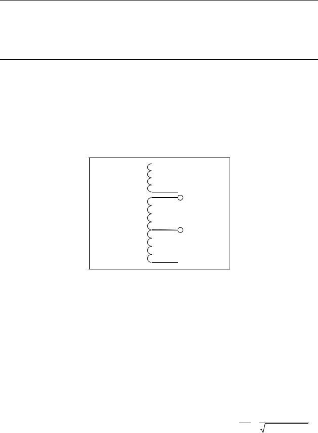
1.1: Single Phase System
A single phase system is a basic two-wire system used in low power distribution applications, such as residential communities or offices. Typically, the voltage is 120V AC. For higher power requirements, such as small commercial facilities, the typical power configuration is two lines of 120V AC opposite in phase (see Figure 1.1 B, below).
This system produces 120 volts from line to neutral for lighting and small appliance use. The line-to-line voltage is 240V AC, used for higher loads such as water heaters, electric dryers, ranges and machinery.
 Line
Line
A)
Single Phase
2 Wires
 Neutral
Line 1
B) |
|
|
Single Phase |
Neutral |
|
3 Wires |
||
|
 Line 2
Figure 1.1: Single Phase System: (A) Two-Wire, (B) Three-Wire
The power (W) in a single phase system is: W =E • I• cosΘ
E = potential, I = current, and cosΘ = phase difference between the potential and the current. Power in a 120/240V AC system is: W = (ELine1 • ILine1 • cosΘ) + (ELine 2 • ILine 2 • cosΘ)
Phase differential between the potential and the current results from a non-resistive load, either reactive or capacitive.
Reactive power (VAR): The additional power consumed that does not produce any work but must be delivered to the load: VAR = E I sinΘ . This is a measure of the inefficiency of the electrical system.
Apparent power (VA): The total power delivered to the load, and the vector sum of real power and reactive power.
Power Factor (PF): The ratio between real power and apparent power: PF = |
W |
= |
W |
|
VA |
|
W 2 + VAR2 |
GE Multilin |
EPM 5000 series Advanced Power Meters |
1 |
CHAPTER 1: AC POWER MEASUREMENT
Apparent Power (VA) |
Reactive |
Power |
|
|
(VAR) |
Real Power (W) |
|
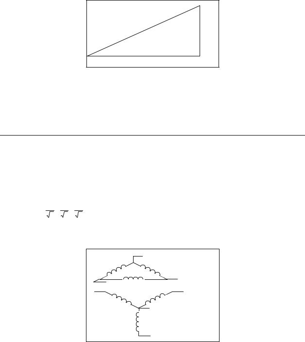
Figure 1.2: Relationship between apparent, real and reactive power
Ideal power distribution should have a PF of 1. This condition can be met only if no reactive power loads exist. In real life applications, many loads are inductive loads. Often, corrective capacitors are installed to correct Poor Power Factor (see Section 1.3).
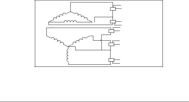
1.2: Three-Phase System
A three-phase system delivers higher levels of power for industrial and commercial applications; the three phases correspond to three potential lines. A 120° phase shift exists between the three potential lines.
A typical configuration has either a Delta connection or a Wye connection (see Figure 1.3, below).
In a three-phase system, the voltage levels between the phases and the neutral are uniform and defined by:
Ean = Ebn = Ecn = Eab3 = Ebc3 = Eac3
A
1) Delta
B
C
A B
2) Wye
N
C
Figure 1.3: Three-Phase System: (1) Delta, (2) Wye
2 |
EPM 5000 series Advanced Power Meters |
GE Multilin |
CHAPTER 1: AC POWER MEASUREMENT
Voltages between the phases vary depending on loading factors and the quality of distribution transformers. The three-phase system is distributed in different voltage levels: 208V AC, 480V AC, 2400V AC, 4160V AC, 6900V AC, 13800V AC, and so on.
Power measurement in a poly phase system is governed by Blondel's Theorem. Blondel’s Theorem states that in a power distribution network which has N conductors, the number of measurement elements required to determine power is N-1. A typical configuration of poly phase system has either a Delta connection or a Wye connection (see Figure 1.4, below).
|
A |
|
X |
EAB IA |
|
|
|
|
|
|
|
|
|
|
||
|
|
|
|
|
|
|
|
|
|
|
|
|
|
|
|
|
1) Delta |
|
|
|
P = EAB IA + ECB I C |
|
|
|
|
|
|
||||||
|
|
|
|
|
|
|
|
|
|
|||||||
C |
|
B |
X |
ECB I C |
|
|
|
|
|
|
|
|
|
|
||
|
|
|
|
|
|
|
|
|
|
|
|
|
|
|||
|
|
|
X |
EAN I A |
|
|
|
|
|
|
|
|
|
|
||
A |
|
B |
|
|
|
|
|
|
|
|
|
|
|
|
|
|
2) Wye |
|
|
X |
EBN I B |
|
|
|
|
|
|
|
|
|
|
||
N |
|
P = E |
I |
|
+ |
E |
|
I |
|
+ |
E |
|
I |
|
||
|
|
|
A |
BN |
B |
CN |
C |
|||||||||
|
|
|
|
AN |
|
|
|
|
|
|
|
|||||
|
C |
|
X |
ECN I C |
|
|
|
|
|
|
|
|
|
|
||
|
|
|
|
|
|
|
|
|
|
|
|
|
||||
Figure 1.4: Poly Phase System: (1) Delta, (2) Wye
1.3: Consumption, Demand and Poor Power Factor
CONSUMPTION: WH = W × T W = instantaneous power T = time in hours The total electric energy usage over a time period is the consumption of WH.
Typically, the unit in which consumption is specified is the kilowatt-hour (KWH): one thousand watts consumed over one hour. Utilities use the WH equation to determine the overall consumption in a billing period.
DEMAND: Average energy consumed over a specified time interval. The utility determines the interval, typically 15 or 30 minutes. The utility measures the maximum demand over a billing period. This measurement exhibits a deviation from average consumption, causing the utility to provide generating capacity to satisfy a high maximum consumption demand. The highest average demand is retained in the metering system until the demand level is reset.
POOR POWER FACTOR: Results in reactive power consumption. Transferring reactive power over a distribution network causes energy loss. To force consumers to correct their Power Factor, utilities monitor reactive power consumption and penalize the user for Poor Power Factor.
GE Multilin |
EPM 5000 series Advanced Power Meters |
3 |
CHAPTER 1: AC POWER MEASUREMENT
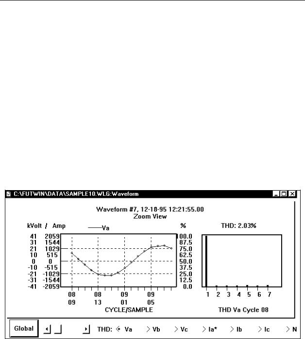
1.4: Waveform and Harmonics
Ideal power distribution has sinusoidal waveforms on voltages and currents. In real-life applications, where inverters, computers, and motor controls are used, distorted waveforms are generated. These distortions consist of harmonics of the fundamental frequency.
SINUSOIDAL WAVEFORM: A • sin (ω t)
DISTORTED WAVEFORM: A • sin(ω• t) + A1 • sin(ω1 • t) + A2 • sin(ω2 • t) + A3 • sin(ω3 • t) +L
TOTAL HARMONIC DISTORTION (THD):
% of THD = |
RMS of Total Harmonic Distortion Signal |
× 100 |
|
RMS of the Fundamenta l Signal |
|
HARMONIC DISTORTION: A destructive force in power distribution systems. It creates safety problems, shortens the life span of distribution transformers, and interferes with the operation of electronic devices. The Futura+ monitors the harmonic distortion to the 31st harmonic. A waveform capture of distorted waveform is also available.
% THD GRAPH
4 |
EPM 5000 series Advanced Power Meters |
GE Multilin |

CHAPTER 2: MECHANICAL INSTALLATION
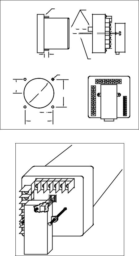
CHAPTER 2
MECHANICAL INSTALLATION
These diagrams display the various possible mechanical installations and Communication Converter installation. The various models use the same hookup and installation.
|
|
|
|
|
|
|
4.50 |
|
|
|
|
|
|
|
SQ. |
MAX |
|
|
AC VOLTS |
||||
MIN |
|
|
A B C |
A |
B |
C |
|
|
|
N N N |
B |
C |
A |
||
LM1 |
|
|
|||||
|
|
|
|
|
|
|
|
MAX |
|
|
AC AMPS |
||||
THD |
|
|
|||||
K |
|
|
|
A B C N |
|
||
|
|
|
|
|
|
|
|
|
|
|
|
POWER |
|||
|
|
|
|
|
PF |
2.0 |
|
|
|
|
|
|
KW |
|
|
|
|
|
|
|
KVA |
||
KVAH |
KWH |
FREQ |
|
KVAR |
|||
MAX/MIN |
VOLTS |
AMPS |
POW ER |
PHASE |
3.0 |
||
LIMITS |
NEXT |
|
|
||||
|
|
4.375 |
|
|
|
|
0.890 |
|
|
SQ. |
|
|
|
|
|
Diagram 2.1: Standard installation
3.50 |
|
|
|
3 FOOT CABLE |
|
|
|
|
|
0.80 |
|
MAX |
|
AC VOLTS |
|
|
|
MIN |
|
A B C A B C |
|
|
|
|
N N N B C A |
|
|
||
LM1 |
|
|
|
|
|
LM2 |
|
|
AC AMPS |
4.50 |
|
THD |
|
|
A B C N |
|
|
K |
|
|
|
SQ. |
|
|
|
|
POWER |
|
|
|
|
|
PF |
|
0.336 |
|
|
|
KW |
|
|
|
|
|
KVA |
|
|
KVAH |
KWH |
FREQ |
KVAR |
|
|
MAX/MIN |
|
|
PHASE |
|
2.45 |
VOLTS AMPS |
POWER |
2.425 |
|
||
LIMITS |
NEXT |
|
|||
|
4.375 |
|
0.890 |
(4) 8-32 SCREWS |
0.714 |
|
SQ. |
|
|||
|
|
|
5.00 |
|
|
|
|
|
|
|
|
Diagram 2.2: Installation with K-110 option for limited space conditions
GE Multilin |
EPM 5000 series Advanced Power Meters |
5 |
CHAPTER 2: MECHANICAL INSTALLATION
SIDE VIEW
(4) 8-32 SCREWS |
FIRST PUT (16) PIN |
|
CONNECTOR TOGETHER. |
||
|
0.80
RECOMMENDED
CUTOUT
0.198 DIA.
1.6875
(2) 8-32 SCREWS WILL LINE UP WITH 2 PEMS ON THE BACK PLATE.
4.0 DIA. |
3.375 |
|
1.6875
3.375
BACK VIEW
Diagram 2.3: Standard cutout
W Port |
Diagram 2.4: Optional Communication Converter or DC Output Module Installation * Recommended wire gauge is 20 AWG for DC Output or RS-485 options.
Note: Carefully line up the guide screw and 8 pin port connector to prevent pin breakage.
6 |
EPM 5000 series Advanced Power Meters |
GE Multilin |
CHAPTER 3: ELECTRICAL INSTALLATION
CHAPTER 3
ELECTRICAL INSTALLATION
3.1: Connecting the Current Circuit
Install the wiring for the current at 600V AC insulation as a minimum. The cable connector should be rated for 6 Amps or greater and have a cross-sectional area of 16 AWG minimum.
Mount the current transformers (CTs) as close as possible to the meter for best accuracy. The following table illustrates the maximum recommended distances for various CT sizes, assuming the connection is via 16 AWG cable.
CT Size |
Maximum Distance (CT to Meter) |
2.5 VA |
10 FEET |
5.0 VA |
15 FEET |
7.5 VA |
30 FEET |
10.0 VA |
40 FEET |
15.0 VA |
60 FEET |
30.0 VA |
120 FEET |
Table 3.1: CT Size and Maximum Distance
WARNING:
DO NOT leave secondary of the CT open when primary current is flowing. This causes high voltage that will overheat the secondary of the CT. Use a shorting block on the secondary of the CT.
3.2: CT Connection
If the meter is connected directly to the current (up to 10 Amps max.), maintain the exact connection to avoid incorrect polarity.
When the meter is connected using the CTs, you must maintain the correct CT polarities. CT polarities are dependent upon correct connections of CT leads, and upon the direction the CTs are facing when clamped around conductors. The dot on the CT must face the line side; the corresponding secondary connection must connect to the appropriate input on the meter. Failure to connect CTs properly results in inaccurate power readings. If your meter is not reading power properly, it is more than likely the CT is incorrectly wired.
Note: CTs are shorted if connected to the terminal block model DSP2 or 3 even if it is detached from the meter.
HELPFUL DEBUGGING TOOLS
OPTION 1: ISOLATING A CT CONNECTION REVERSAL POWER READING
If your meter does not read the correct watts after installation, it almost always means that the CT’s have been wired in the wrong polarity. To check the polarity of the CT after the monitor has been installed, look at the single phase WATT readings to see that each of the readings are positive (assuming you are consuming power). If one of the WATT readings is negative, that particular phase CT is reversed.
To check the single phase WATT reading, press the Power button twice while the annunciator is positioned to WATTS. Then press the Phase/Next button to cycle through the phases. After connecting the polarity of the CTs, the WATT and VAR readings should be correct.
GE Industrial Systems |
5300P Advanced Power Meter |
7 |

CHAPTER 3: ELECTRICAL INSTALLATION
OPTION 2: ISOLATING A CT CONNECTION REVERSAL USING VOLTAGE READINGS
!Remove potential connections to terminals 6 and 7. Observe the KW reading. It should be positive.
!If negative, reverse the CT wires on terminals 8 and 9.
Connect terminal number 6 potential. If KW decreases to about zero, reverse CT wires on terminals 10 and 11.
Connect terminal number 7 potential. If KW is one-third of expected reading, reverse CT wires to terminals 12 and 13.
3.3: Connecting the Voltage Circuit
For proper meter operation, the voltage connection must be maintained. The voltage must correspond to the correct terminal.
The cable required to terminate the voltage sense circuit should have an insulation rating greater than 600V AC and a current rating greater than 0.1 A.
3.4: Selecting the Voltage Fuses
We strongly recommend using fuses on each of the sense voltages and the control power, although connection diagrams do not show them. Use a 1 Amp fuse on each voltage input.
The meter can handle a maximum voltage of 150V phase to neutral. PTs are required for higher voltages. Suffix -G extends the maximum direct voltage to 300V phase to neutral, 600 volt phase to phase.
3.5: Connection to the Main Power Supply
The meter requires separate control power to operate. Listed are the five different power supply options and corresponding suffixes.
CONTROL POWER |
OPTION SUFFIX |
CURRENT |
120V AC |
115 A |
0.1 AAC |
240V AC |
230 A |
0.05 AAC |
12V DC |
D4 |
0.10 ADC |
24-48V DC |
D |
0.25-0.5 ADC |
125V AC/DC (universal) |
D2 |
0.10 AAC or DC |
Table 3.2: Control Power and Current
Note: For DC-powered units, polarity should be observed. Connect the negative terminal to L and positive terminal to L1. An earth ground connection to chassis is mandatory for normal operation (terminal three). Do not ground the unit through the negative of the DC supply.
Note: Externally fuse power supply with a slow-blow 3 Amp fuse.
3.6: Electrical Connection Installation
Choose the diagram that best suits your application and maintain the CT polarity. Follow the outlined procedure to verify correct connection. IMPORTANT: For PT connections only, short terminals 3 and 4. Connect local ground to terminal 3. This protects the unit from spikes and transients.
8 |
EPM 5000 series Advanced Power Meters |
GE Multilin |
CHAPTER 3: ELECTRICAL INSTALLATION
•The meter and terminal module DSP3 are factory calibrated together; the serial numbers are matched on both. The DSP3 input module and the meter base MUST MATCH!
•Mismatching of the meter and DSP3 input module will cause inaccurate readings because calibration ratios are stored in the meter’s memory, not in the DSP3 input module.
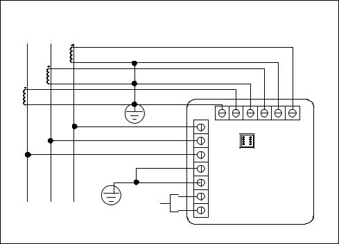
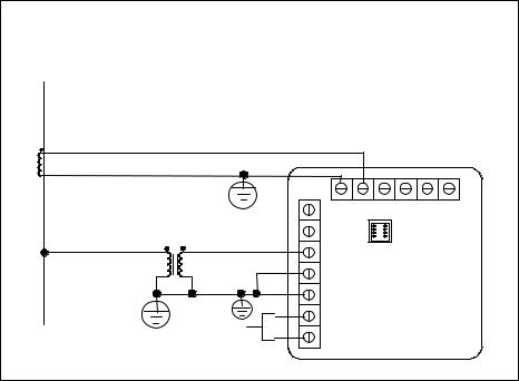
LIST OF CONNECTION DIAGRAMS
NOTE: See phase reversal if a message of CBA appears after installation.
IThree-Phase, Three-Wire System Delta with Direct Voltage and CTs
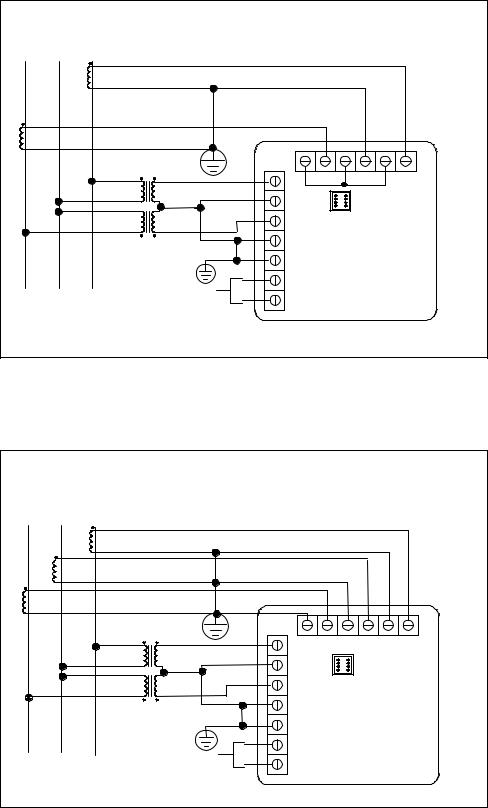
IIThree-Phase, Three-Wire Open Delta with two CTs and two PTs
(Open Delta System should only be used if the electrical system is a 3-wire 2 PT OPEN DELTA Open Delta can be enabled or disabled in Programming GROUP 0, FUNCTION 3, Chapter 9, section 9.4)
III Three-Phase, Three-Wire Open Delta with three CTs and two PTs
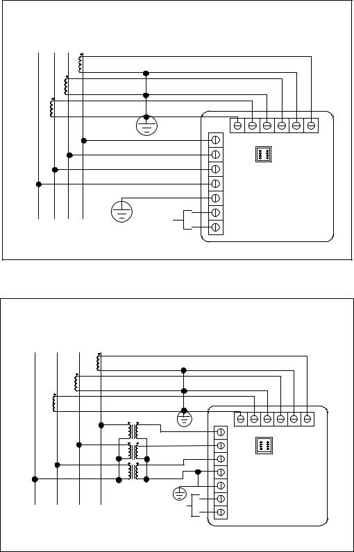
IV Three-Phase, Four-Wire Wye with Direct Voltage and CTs
V Three-Phase, Four-Wire Wye with CTs and PTs
VI Single Phase with CT and PT Connection
VII Dual-Phase System
VIII Three Phase System
|
LINE |
|
|
|
|
BACK VIEW |
|
|||
A |
B |
C |
|
|
|
|
||||
|
|
|
|
7 |
8 |
9 |
10 |
11 |
12 |
13 |
|
|
|
|
6 |
|
|
|
|
|
|
|
|
|
|
5 |
|
PORT |
|
|
|
|
|
|
|
|
|
|
|
|
|
|
|
|
|
|
|
4 |
|
|
|
|
|
|
|
|
|
|
3 |
|
|
|
|
|
|
|
|
CONTROL |
+ |
2 |
L1 |
|
|
|
|
|
|
|
POWER |
|
|
|
|
||||
|
LOAD |
|
|
|
|
|
|
|
|
|
|
|
- |
1 L |
|
|
|
|
|
||
I. Three Phase, Three-Wire System Delta with Direct Voltage and CTs
Note: Remember to make sure Open Delta bit is programmed in the meters (See Chapter 9).
GE Multilin |
EPM 5000 series Advanced Power Meters |
9 |
CHAPTER 3: ELECTRICAL INSTALLATION
|
LINE |
|
BACK VIEW |
|
|
||||
A |
B |
C |
|
|
|||||
|
|
|
|
|
|
|
|||
|
|
|
7 |
8 |
9 |
10 |
11 |
12 |
13 |
|
|
|
6 |
|
|
|
|
|
|
|
|
|
5 |
|
|
PORT |
|
|
|
|
|
|
|
|
|
|
|
|
|
|
|
|
4 |
|
|
|
|
|
|
|
|
|
3 |
|
|
|
|
|
|
|
|
+ |
2L1 |
|
|
|
|
|
|
|
LOAD |
POWER |
|
|
|
|
|
|
|
|
- |
1 L |
|
|
|
|
|
|
|
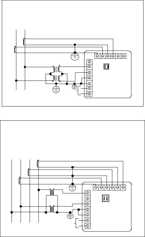
II. Three-Phase, Three-Wire Open Delta with two CTs and two PTs
Note: Remember to make sure Open Delta bit is programmed in the meter (see section 9.4).
|
LINE |
|
BACK VIEW |
|
|
|||
A |
B |
C |
|
|
||||
|
|
|
|
|
|
|||
|
|
|
7 8 |
9 |
10 |
11 |
12 |
13 |
|
|
|
6 |
|
|
|
|
|
|
|
|
5 |
PORT |
|
|
|
|
|
|
|
4 |
|
|
|
|
|
|
|
|
3 |
|
|
|
|
|
|
|
+ |
2 L1 |
|
|
|
|
|
|
LOAD |
POWER |
1 L |
|
|
|
|
|
|
- |
|
|
|
|
|
||
III. Three-Phase, Three-Wire Open Delta with three CTs and two PTs
Note: Remember to make sure Open Delta bit is programmed in the meter (see Chapter 9).
10 |
EPM 5000 series Advanced Power Meters |
GE Multilin |
CHAPTER 3: ELECTRICAL INSTALLATION
|
LINE |
|
|
|
BACK VIEW |
|
|
|||
N |
A B |
C |
|
|
|
|
||||
|
|
|
|
7 |
8 |
9 |
10 |
11 |
12 |
13 |
|
|
|
|
6 |
|
|
|
|
|
|
|
|
|
|
5 |
|
|
PORT |
|
|
|
|
|
|
|
4 |
|
|
|
|
|
|
|
|
|
|
3 |
|
|
|
|
|
|
|
|
CONTROL |
+ |
2 |
L1 |
|
|
|
|
|
|
|
POWER |
|
|
|
|
|
|||
|
LOAD |
|
|
|
|
|
|
|
|
|
|
|
- |
1 |
L |
|
|
|
|
|
|
|
|
|
|
|
|
|
|
|||
IV. Three-Phase Four-Wire Wye with Direct Voltage and CTs
|
LINE |
|
|
BACK VIEW |
|
|
||||
N |
A |
B |
C |
|
|
|
||||
|
|
|
|
|
|
|
||||
|
|
|
|
7 |
8 |
9 |
10 |
11 |
12 |
13 |
|
|
|
|
6 |
|
|
|
|
|
|
|
|
|
|
5 |
|
PORT |
|
|
|
|
|
|
|
|
4 |
|
|
|
|
|
|
|
|
|
|
3 |
|
|
|
|
|
|
|
|
|
+ |
2 L1 |
|
|
|
|
|
|
|
|
|
POWER |
|
|
|
|
|
|
|
|
LOAD |
|
- |
1 L |
|
|
|
|
|
|
|
|
|
|
|
|
|
|
|||
V. Three Phase Four-Wire Wye with CT and PTs
GE Multilin |
EPM 5000 series Advanced Power Meters |
11 |
CHAPTER 3: ELECTRICAL INSTALLATION
The EPM 5300P-S
The EPM 5300P -S is essentially the 5300P, where through the Programming Mode calculations are changed to reflect either Single Phase or Dual Phase readings.
Single Phase—The connection MUST be identical to Diagram VI.
Dual Phase—The connection MUST be identical to Diagram VII.
Program 1 for Single Phase or 2 for Dual Phase in GROUP 0, FUNCTION 7 to remove Three-Phase indicators from view.
LINE |
|
|
BACK VIEW |
|
|
|||
A |
|
|
|
|
||||
|
|
|
|
|
|
|
|
|
|
|
7 |
8 |
9 |
10 |
11 |
12 |
13 |
|
|
6 |
|
|
|
|
|
|
|
|
5 |
|
|
PORT |
|
|
|
|
|
|
|
|
|
|
|
|
|
|
4 |
|
|
|
|
|
|
|
|
3 |
|
|
|
|
|
|
|
+ |
2 |
L1 |
|
|
|
|
|
LOAD |
POWER |
|
|
|
|
|
|
|
- |
1 L |
|
|
|
|
|
||
VI. Single Phase with CT and PT Connection
12 |
EPM 5000 series Advanced Power Meters |
GE Multilin |
CHAPTER 3: ELECTRICAL INSTALLATION
LINE |
|
|
BACK VIEW |
|
|
||||
A |
B |
|
|
|
|
||||
|
|
|
|
|
|
|
|
||
|
|
|
7 |
8 |
9 |
10 |
11 |
12 |
13 |
|
|
|
6 |
|
|
|
|
|
|
|
|
|
5 |
|
PORT |
|
|
|
|
|
|
|
4 |
|
|
|
|
|
|
|
|
|
3 |
|
|
|
|
|
|
|
|
+ |
2 L1 |
|
|
|
|
|
|
LOAD |
POWER |
1 L |
|
|
|
|
|
||
- |
|
|
|
|
|
||||
VII. Dual-Phase with CTs and PTs
|
LINE |
|
|
|
|
|
|
|
|
|
|
N |
A |
B |
C |
|
|
BACK VIEW |
|
|
|||
|
|
|
|
|
|
|
|
||||
|
|
|
|
|
7 |
8 |
9 |
10 |
11 |
12 |
13 |
|
|
|
|
|
6 |
|
|
|
|
|
|
|
|
|
|
|
5 |
|
PORT |
|
|
|
|
|
|
|
|
|
4 |
|
|
|
|
|
|
|
|
|
|
|
3 |
|
|
|
|
|
|
|
|
|
CONTROL |
+ |
2 |
L1 |
|
|
|
|
|
|
|
|
|
|
|
|
|
|
|||
|
LOAD |
POWER |
- |
1 |
L |
|
|
|
|
|
|
|
|
|
|
|
|
|
|||||
|
|
|
|
|
|
|
|
||||
VIII. Three-Phase Four-Wire WYE with 2.5 Element
Note: The 2.5 element option must be custom configured from the factory. You must pre-order this configuration.
GE Multilin |
EPM 5000 series Advanced Power Meters |
13 |

CHAPTER 3: ELECTRICAL INSTALLATION
3.7: Relay, Protection and Pulse Output
(This section applies only to the -NL or -NL2 Relay Option.)
EPM 5300P RELAY OVERVIEW
The EPM 5300P offers dry contact relay output capability. The EPM 5200P only offers KYZ pulse outputs and cannot be configured to trip contacts on events.
FAIL-SAFE MODE: The EPM 5300P -NL option gives the user an adjustable tripping bandwidth. The user specifies a range over which functions, such as frequency, phase relation and voltage, are acceptable. The relay releases during times of normal operation, and engages when functions are outside specified normal levels. The relay can be programmed to engage during normal operating conditions, and release outside specified normal range (particularly when power is lost). This is the fail-safe mode.
HYSTERISIS: The EPM 5300P -NL option also includes adjustable hysterisis. In addition to a time delay on activating any contact, the user may specify a lower level to release the relay, rather than releasing after the initial alarm point. This is ideal during load shedding when an alarm activates at a certain level and the user does not want to turn off the alarm until a much lower, safer level.
SETABLE DELAYS: After reaching the alarm point, a change in relay status may be delayed for 255 seconds. The user also has the option of allowing the device to change relay status without any delay. After the alarm condition passes, the relay can be stopped from returning to a normal condition for a programmable time. Each delay time is independent of one another.
AND/OR LOGIC: If several parameters are assigned to one relay, the user can trip the relay if all functions are out of limit (and programming), or if one function is out of limit (or programming). For example, if limits on Voltage, Kilowatts, and Phase Imbalance are programmed and tied to Relay 1, the user can either trip the relay if one function is out of limit, or if all functions are out of limit.
2 RELAYS & 1 KYZ PULSE OUTPUT -NL OPTION
The EPM 5300P's flexibility accesses a variety of relay options through the Programming Mode (see programming sections). The relay option package consists of three relays: two can be dedicated to alarm or controlled through communication (or both) and one for KYZ pulse output.
If the relays are controlled through communication, there are two different modes:
|
Lock ON |
Relay will not be affected by any alarm condition. |
|
Lock OFF |
Relay will not be affected by any alarm condition. |
If the relays are used for communication and alarm, there are four different modes:
|
Lock ON |
Relay stays on regardless of any alarm condition. |
|
Lock OFF |
Relay stays off regardless of any alarm condition. |
|
Free ON |
Relay turns on unless other conditions force it off. |
|
Free OFF |
Relay turns off unless other conditions force it on. |
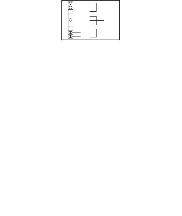
Relay connection (see Figure 3.1, below): Form C relays, rated 250V, 5A–2 each.
KYZ relay output (Form C), rated 200V, 100mA–1 each.
14 |
EPM 5000 series Advanced Power Meters |
GE Multilin |
CHAPTER 3: ELECTRICAL INSTALLATION
20 |
|
|
|
|
N.O. |
ALARM #1 |
21 |
|
|
|
|
N.C. |
|
|
|
|
|
22 COM
COM
23 N.O.
N.O.
24 |
|
|
N.C. |
ALARM #2 |
|
|
25 COM
COM
26 K
K
27 |
Y |
PULSE |
28 |
Z |
OUTPUT |
|
Figure 3.1: Close-up of the Relay and KYZ pulse output on the rear panel.
Note: The relays shown in the figure above are in the NOT energized state.
THE INSTRUMENT DETECTS TWO LEVELS OF ALARM FOR THE FOLLOWING FUNCTIONS:
|
Voltage: |
AN, BN, CN, AB, BC, CA |
|
Current: |
A, B, C, N |
Over and Reverse Power
Under PF/KVAR Lead or Lag
Over KVA
Voltage Imbalance (One level only)
Over/Under Frequency
Voltage Phase Reversals (One level only)
Over/Under %THD (Available only with option –H)
Over/Under K-Factor
KYZ RELAYS: Provides pulses for energy management systems or any other type of recording device. These pulses represent accumulated watt-hour, negative watt-hour, or VA-hour. Accomplish this assignment through the Programming Mode (see programming sections). The pulse value is determined by the decimal increment of the power function assigned to the pulse. The EPM 5200P can be equipped with KYZ pulse outputs.
NOTE: Unless otherwise specified, standard KYZ setup represents positive watt hour. See table below for standard rate. The scale factor for wattage (KW or MW) and Full Scale Decimal Point Placement is selectable in Programming Mode GROUP 1, FUNCTION 2. Follow the Decimal Point Placement corresponding to the Change in Level. A multiplication or division factor can be programmed. See Programming GROUP 0, FUNCTION 6 for a different rate.
STANDARD RATE TABLE FOR WATTS*
DECIMAL POINT PLACEMENT |
CHANGE IN LEVEL |
(KW/MW) |
|
9999.000 |
1.0 Units W-Hour |
999.900 |
0.1 Units W-Hour |
99.990 |
0.01 Units W-Hour |
9.999 |
0.001 Units W-Hour |
*Units could be KiloWatts or MegaWatts.
3.8: KYZ Pulse Outputs: NL2 Option
The -NL2 option for the meter is equipped with three KYZ outputs. KYZ relays provide pulses for energy management systems or any other type of recording device. These pulses represent accumulated positive watt-hour, negative watt-hour, VA-hour, positive VAR-hour, or negative VAR-hour. Accomplish this through Programming Mode GROUP 0, FUNCTION 6. The pulse value is dependent upon the Decimal Point Placement and is determined by the decimal increment of the power function assigned to the pulse. Refer to the situation that applies to the meter setting.
GE Multilin |
EPM 5000 series Advanced Power Meters |
15 |

CHAPTER 3: ELECTRICAL INSTALLATION
Note: Unless otherwise specified, standard KYZ setup for Pulse Output 0 is positive Watt Hour, Pulse Output 1 is negative Watt-Hour, and Pulse Output 2 is VA-hour. See table below for standard rate.
Note: With Option R (available only with the EPM 5200P) the setup for Pulse Output 0 is positive Watt-Hour, Pulse output 1 is positive VAR-hour, and Pulse output 2 is negative VAR-hour.
The scale factor for Wattage (KW or MW) and Full Scale Decimal Point Placement is selectable in Programming Mode GROUP 1, FUNCTION 2. Follow the Decimal Point Placement corresponding to the Change in Level. A multiplication or division factor can be programmed. See Programming GROUP 0, FUNCTION 6 for a different rate.
STANDARD RATE TABLE FOR WATTS*
DECIMAL POINT PLACEMENT |
CHANGE IN LEVEL |
(KW/MW) |
|
9999.0 |
1.0 Units W Hour |
999.9 |
0.1 Units W Hour |
99.99 |
0.01 Units W Hour |
9.999 |
0.001 Units W Hour |
*Units could be KiloWatts or MegaWatts.
2 0 |
|
|
|
|
K |
|
|
|
|
|
|
|
|
|
|
||
|
|
|
|
|
|
|
||
2 1 |
|
|
|
|
Y |
|
|
P U L S E |
|
|
|
|
|
|
|||
|
|
|
|
|||||
|
|
|
|
|
|
|||
2 2 |
|
|
|
|
Z |
|
|
O U T P U T 2 |
|
|
|
|
|
||||
|
|
|
|
|
||||
|
|
|
|
|
|
|
||
2 3 |
|
|
|
|
K |
|
|
|
|
|
|
|
|
|
|||
|
|
|
|
|
||||
|
|
|
|
|
|
|||
2 4 |
|
|
|
|
Y |
|
P U L S E |
|
|
|
|
|
|
||||
|
|
|
|
|
|
|
|
|
2 5 |
|
|
|
|
Z |
|
|
O U T P U T 1 |
|
|
|
||||||
|
|
|
|
|||||
2 6 |
|
|
|
|
K |
|
|
|
|
|
|
|
|
|
|||
|
|
|
|
|
||||
|
|
|
|
|
|
|||
2 7 |
|
|
|
|
Y |
|
P U L S E |
|
|
|
|
|
|
||||
|
|
|
|
|
|
|
|
|
2 8 |
|
|
|
|
Z |
|
O U T P U T 0 |
|
|
|
|
||||||
|
|
|
|
|||||
|
|
|
|
|
|
|
|
|
|
|
|
|
|
|
|
|
|
Figure 3.2: KYZ Relay Connection for -NL2 Option
KYZ relay output (Form C), rated 200V, 100mA: 3 separate KYZ Outputs (labeled 0 through 2).
16 |
EPM 5000 series Advanced Power Meters |
GE Multilin |
CHAPTER 4: COMMUNICATION INSTALLATION
CHAPTER 4
COMMUNICATION INSTALLATION
4.1: RS-232C
(This section applies to the RS-232C or RS-485.)
All EPM 5300P and 5200P instruments can be equipped with RS-232C or RS-485 communication.
RS-232C communication links a single instrument with a computer or device such as an RTU or PLC. Its capability is up to 100 feet. A standard 9-pin female serial port connector mounts on the instrument for direct connection to a computer with a 9-pin cable.
BACK VIEW
RS-232 COMMUNICATION CONNECTION
8 9 10 11 12 13
7 |
|
|
CONNECTION FOR DB-9 FEMALE |
||||
|
20 |
|
|
|
|
||
|
|
PIN 2 - RECEIVE OF THE HOST/COMPUTER |
|||||
6 |
|
21 |
|||||
5 |
COMMUNICATION |
22 |
PIN 3 - TRANSMIT OF THE HOST/COMPUTER |
||||
PIN 5 - GROUND OF THE HOST/COMPUTER |
|||||||
4 |
CONVERTER |
23 |
|||||
|
|
|
|
|
|||
Model |
24 |
|
|
|
|
||
3 |
5 |
4 3 2 1 |
|||||
SF-232DB3 |
25 |
||||||
|
|
|
|
||||
2 |
|
|
|
|
DETAIL OF DB-9 |
||
|
26 |
|
|
|
|||
|
|
|
9 8 |
7 |
6 |
||
1 |
|
27 |
|
||||
|
|
|
|
|
|||
|
|
|
|
|
|
||
|
|
28 |
|
|
|
|
|
LAPTOP
DB-9 CONNECTOR
A DIRECT PIN-TO-PIN CABLE CAN BE USED.
NO NULL MODEM IS REQUIRED.
Figure 4.1: RS-232C Communication Connection Installation
Note: To avoid ground loops, the neutral and safety ground (pin 3) should be connected together at only one point.
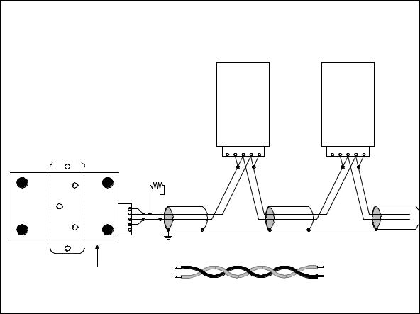
4.2: RS-485
Each EPM 5300P or 5200P instrument has a unique address up to four digits long. This allows the user to communicate with up to 10,000 instruments. Available standard baud rates are 1200, 2400, 4800, and 9600. To select the proper baud rate, apply the following rules:
The unit operates up to 9600 baud. For a smaller number of instruments over a long distance, use a lower baud rate. Optimal recommended baud rate is 1200 baud, if noisy conditions exist.
GE Multilin |
EPM 5000 series Advanced Power Meters |
17 |
CHAPTER 4: COMMUNICATION INSTALLATION
RS-485 Hookup Diagram (2 wire) Half Duplex |
5300P Instruments (rear view) |
RS-485 |
Communications Port |
Model#SF485DB |
RT |
RT |
RS-485 |
UNICOM 2500 |
(Bottom View Shown) |
RS-232 |
PC |
(+) (-) |
Figure 4.2: 2-Wire RS-485 Communication Connection Installation half duplex —Detail view on following page
18 |
EPM 5000 series Advanced Power Meters |
GE Multilin |
CHAPTER 4: COMMUNICATION INSTALLATION
RS-485 Hookup Diagram (2 wire) Half Duplex (Closed Loop)
5300P Instruments (rear view)
RS-485 |
Communications Port |
Model #SF485DB |
RS-232 |
RS-485 |
UNICOM 2500
(Bottom View Shown)
Figure 4.3: 2-Wire RS-485 Communication Connection Installation half duplex (closed loop)
GE Multilin |
EPM 5000 series Advanced Power Meters |
19 |
CHAPTER 4: COMMUNICATION INSTALLATION
|
RS-485 Hookup Diagram (2 wire) Half Duplex: Detail View |
||
|
|
RS-485 |
RS-485 |
|
|
Communications |
Communications |
|
|
Port |
Port |
|
|
Model# |
Model# |
|
|
SF485DB |
SF485DB |
|
|
G R+ T+ R- T- |
G R+ T+ R- T- |
|
|
RT |
|
RS |
RS |
|
|
232- |
485- |
T- |
|
R- |
|
||
T+ |
|
||
|
|
|
|
|
|
R+ |
|
|
|
Gnd |
|
|
|
)-( |
|
|
UNICOM 2500 |
(+) |
|
|
|
|
|
|
(Bottom View Shown) |
|
|
Figure 4.4: 2-Wire RS-485 Communication Connection Installation half duplex, detail view
20 |
EPM 5000 series Advanced Power Meters |
GE Multilin |
CHAPTER 4: COMMUNICATION INSTALLATION
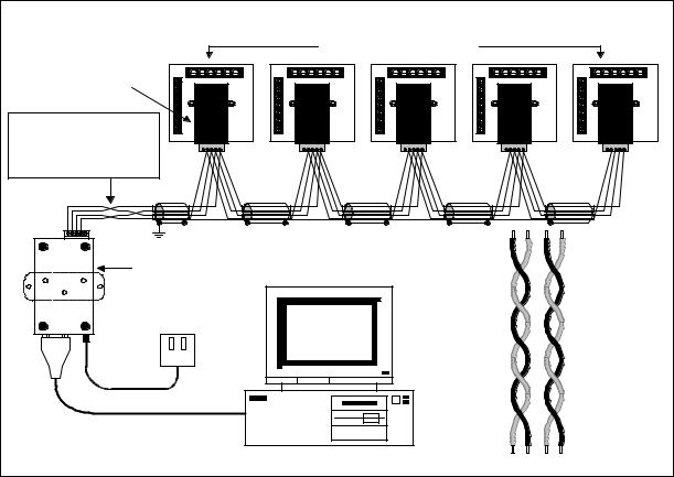
RS-485 Hookup Diagram (4 wire) Full Duplex
5300P Instruments (rear view)
RS-485
Communications Port
Model#SF485DB
Note: This does not represent a twisted pair. It shows the cross-over from R to T between the Unicom and the rest of the bus.
RS-485 |
RS-232 |
UNICOM 2500
(Bottom View Shown)
PC
R+ R- T+ T-
Figure 4.5: 4-Wire RS-485 Communication Connection Installation full duplex —Detail view on following page
Connecting 4-Wire bus to RS-485 Port:
•Connect the T- wire of the Unicom 2500 to the R- on the RS-485 port
•Connect the R- wire of the Unicom 2500 to the T- on the RS-485 port
•Connect the T+ wire of the Unicom 2500 to the R+ on the RS-485 port
•Connect the R+ wire of the Unicom 2500 to the T+ on the RS-485 port
GE Multilin |
EPM 5000 series Advanced Power Meters |
21 |
CHAPTER 4: COMMUNICATION INSTALLATION
RS-485 Hookup Diagram (4 wire) Full Duplex: Detail View
Note: This does not represent a twisted pair. It shows the cross-over from R to T between the Unicom and the rest of the bus.
-RS |
-RS |
T- |
|
232 |
485 |
||
R- |
|||
|
|
T+ |
|
|
|
R+ |
|
|
|
Gnd |
UNICOM 2500
(Bottom View Shown)
RS-485
Communications
Port
Model#
SF485DB
G |
R+ |
T+ |
R- |
T- |
RS-485
Communications
Port
Model#
SF485DB
G |
R+ |
T+ |
R- |
T- |
Enlarged view of twisted pair segments
|
Receive Pair |
-R |
R- |
R+ |
R+ |
|
Transmit Pair |
-T |
T- |
T+ |
T+ |
Figure 4.6: 4-Wire RS-485 Communication Connection Installation full duplex, detail view
Connecting 4-Wire bus to RS-485 Port:
•Connect the T- wire of the Unicom 2500 to the R- on the RS-485 port
•Connect the R- wire of the Unicom 2500 to the T- on the RS-485 port
•Connect the T+ wire of the Unicom 2500 to the R+ on the RS-485 port
•Connect the R+ wire of the Unicom 2500 to the T+ on the RS-485 port
22 |
EPM 5000 series Advanced Power Meters |
GE Multilin |
CHAPTER 4: COMMUNICATION INSTALLATION
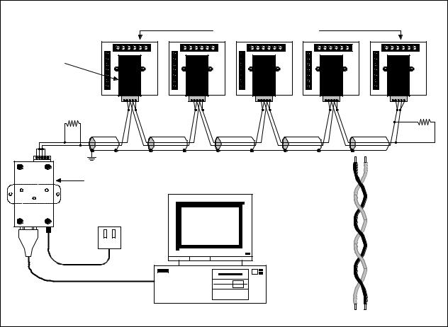
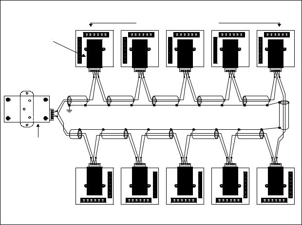
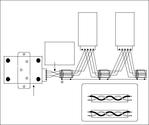
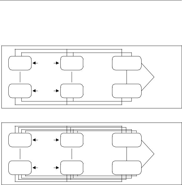
4.3: Network of Instruments and Long Distance Communication
The RS-485 Transceiver is required for a large network of instruments.
•In a two-wire connection, a maximum of 900 instruments can be included in the same network (Figure 4.7)
•In a four-wire connection, a maximum of 3600 instruments can be included in the same network (Figure 4.8).
|
|
|
RS-485 |
|
DEVICE |
32 UNITS |
DEVICE |
TRANSCEIVER |
|
|
|
|
(Acts as Repeater) |
|
|
|
|
32 |
COMPUTER |
|
|
|
TRANSCEIVERS |
|
|
|
|
|
|
|
|
|
RS-485 |
|
DEVICE |
32 UNITS |
DEVICE |
TRANSCEIVER |
|
|
|
|
(Acts as Repeater) |
|
Figure 4.7: 2-Wire RS-485 Communication Installation Connection with Transceiver
DEVICE |
32 UNITS |
DEVICE |
RS-485 |
|
TRANSCEIVER |
|
|||
|
|
|
(Acts as Repeater) |
|
|
|
|
32 |
COMPUTER |
|
|
|
TRANSCEIVERS |
|
|
|
|
|
|
DEVICE |
32 UNITS |
DEVICE |
RS-485 |
|
TRANSCEIVER |
|
|||
|
|
|
(Acts as Repeater) |
|
Figure 4.8: 4-Wire RS-485 Communication Installation Connection with Transceiver
Use modems (dedicated or dial-up) when the instruments are located at great distances. However, set the modem to auto answer at the recommended value of 1200 baud rate, if noise conditions exist. Also, flow control must be disabled.
GE Multilin |
EPM 5000 series Advanced Power Meters |
23 |
CHAPTER 4: COMMUNICATION INSTALLATION
YOU MAY WANT TO USE A MODEM MANAGER RS485-RS232 CONVERTER
When speaking to most RS-485 or RS-232C based devices, the remote modem must be programmed for the communication to work. This task is often quite complicated because modems are quirky when talking to remote devices. To make this task easier, EIG has designed a Modem Manager RS-485 to RS-232C converter. This device automatically programs the modem to the proper configuration. Also, if you have poor telephone lines, modem manager acts as a line buffer, making the communication more reliable.
I. MODEM CONNECTED TO COMPUTER (ORIGINATE MODEM)
Programming the Modem
Comply with the modem’s instruction manual and follow these instructions:
RESTORE MODEM TO FACTORY SETTINGS:
•This procedure erases all previously programmed settings.
SET MODEM TO DISPLAY RESULT CODES:
•The device uses the result codes.
SET MODEM TO VERBAL RESULT CODE:
•The device uses the verbal codes.
SET MODEM TO IGNORE DTR SIGNAL:
•Necessary for the device to ensure connection with originate modem.
SET MODEM TO DISABLE FLOW CONTROL:
• Necessary to communicate with remote modem connected to device.
TELL MODEM TO WRITE THE NEW SETTINGS TO ACTIVATE PROFILE:
•Places these settings into nonvolatile memory; the settings take effect after the modem powers up.
II. MODEM CONNECTED TO THE DEVICE (REMOTE MODEM)
Programming the Modem
Comply with the modem’s instruction manual and follow these instructions:
RESTORE MODEM TO FACTORY SETTINGS:
•This procedure erases all previously programmed settings.
SET MODEM TO AUTO ANSWER ON N RINGS:
• Sets the remote modem to answer the call after n rings.
SET THE MODEM TO AUTO NEGOTIATE MODE:
•Sets the remote to auto negotiate to communicate successfully with EPM 5300P and other devices in the modem.
SET MODEM TO RETURN NUMERIC RESULT CODES:
•Increases speed connection with EPM 5300P.
SET MODEM TO IGNORE DTR SIGNAL:
•Necessary for device to ensure connection with originate modem.
SET MODEM TO DISABLE FLOW CONTROL:
• Necessary to communicate with remote modem connected to EPM 5300P.
TELL THE MODEM TO WRITE THE NEW SETTINGS TO ACTIVATE PROFILE:
•Places new settings into nonvolatile memory; settings take effect after the modem powers up.
24 |
EPM 5000 series Advanced Power Meters |
GE Multilin |
CHAPTER 4: COMMUNICATION INSTALLATION
Debugging Communication Problems
If you experience NO communication, check these conditions:
•Is the Baud Rate set correctly (see Part II: Programming Section)?
•Is the Meter Address set correctly (see Part II: Programming Section)?
•Is the correct protocol set? Modbus, DNP 3.0?
•Set the meter for the appropriate protocol for the internal software.
GE Multilin |
EPM 5000 series Advanced Power Meters |
25 |
CHAPTER 4: COMMUNICATION INSTALLATION
26 |
EPM 5000 series Advanced Power Meters |
GE Multilin |
Loading...