


CSG14U
www GarrettCom com
..
Magnum CSG14 Gigabit Converter Switches
CSG14U
CSG14
Installation and User Guide

CSG14 Series Gigabit Converter Switch Installation and User Guide (05/09)
i
www GarrettCom com
..
Magnum
TM
CSG14 Series Gigabit Converter Switch
Installation and User Guide
Part #: 84-00102Z Rev. G
Trademarks
GarrettCom is a registered trademark and Magnum, Dymec, DynaStar, Personal
Switch, Link-Loss-Learn, S-Ring, Convenient Switch and Converter Switch
are trademarks of GarrettCom, Inc.
Ethernet is a trademark of Xerox Corporation
NEBS is a trademark of Telcordia Technologies
UL is a registered trademark of Underwriters Laboratories

CSG14 Series Gigabit Converter Switch Installation and User Guide (05/09)
ii
www GarrettCom com
..
Important: The Magnum CSG14 Series 10/100/1000 Mb/s Converter
Switches contain no user serviceable parts. Attempted service by unauthorized
personnel shall render all warranties null and void. If problems are
experienced with Magnum CSG14 10/100/1000 Mb/s Converter Switch
products, consult Section 5, Troubleshooting, of this User Guide.
Copyright © 2008 GarrettCom, Inc. All rights reserved. No part of this publication may
be reproduced without prior written permission from GarrettCom, Inc.
Printed in the United States of America
GarrettCom, Inc. reserves the right to change specifications, performance characteristics
and/or model offerings without notice.

CSG14 Series Gigabit Converter Switch Installation and User Guide (05/09)
iii
www GarrettCom com
..
Federal Communications Commission
Radio Frequency Interference Statement
This equipment generates, uses and can radiate frequency energy and if not
installed and used properly, that is in strict accordance with the manufacturer's
instructions, may cause interference to radio communication. It has been tested and
found to comply with the limits for a Class A computing device in accordance with the
specifications in Subpart J of Part 15 of FCC rules, which are designed to provide
reasonable protection against such interference when operated in a commercial
environment. Operation of this equipment in a residential area is likely to cause
interference, in which case the user, at his/her own expense, will be required to take
whatever measures may be required to correct the interference.

CSG14 Series Gigabit Converter Switch Installation and User Guide (05/09)
iv
www GarrettCom com
..
Electrical Safety requirements:
1. This product is to be installed Only in Restricted Access Areas
(Dedicated Equipment Rooms, Electrical Closets, or the like).
2. 48VDC products shall be installed with a readily accessible disconnect
device in the building installation supply circuit to the product.
3. This product shall be provided with a maximum 10A DC Listed fuse or
circuit breaker in the supply circuit when connected to a 48V
centralized source.
4. The external power supply for DC units shall be Listed, Direct Plug In
power unit, marked Class 2, or listed ITE Power Supply, marked LPS,
which has suitably rated output voltage (i.e. 24VDC or 48VDC) and suitable
rated output current.
5. Product does not contain user replaceable fuses. Any internal fuses can
ONLY be replaced by GarrettCom personnel through the RMA process.

CSG14 Series Gigabit Converter Switch Installation and User Guide (05/09)
v
www GarrettCom com
..
Contacting GarrettCom, Inc
Please use the mailing address, phone and fax numbers and email address listed below:
GarrettCom, Inc.
47823 Westinghouse Drive
Fremont, CA 94539
Phone (510) 438-9071
Fax (510) 438-9072
Website: http://www.GarrettCom.com
Email: support@garrettcom.com

CSG14 Series Gigabit Converter Switch Installation and User Guide (05/09)
vi
www GarrettCom com
..
TABLE OF CONTENTS Page
1.0 SPECIFICATIONS ............................................................................... 1
1.1 Technical Specifications ...................................................................... 1
1.2 Summary of models and descriptions: ............................................... 11
2.0 INTRODUCTION ............................................................................... 16
2.1 Inspecting the Package and the Product ............................................. 16
2.2 Product Description ........................................................................... 17
2.2.1 CSG14H / CSG14P Product Description ................................... 17
2.2.2 CSG14UH / CSG14UP Product Description ............................. 23
2.3 Frame Buffering and Latency ............................................................ 29
2.4 Features and Benefits ......................................................................... 32
2.5 Applications for CSG14 Series Converter Switches .......................... 35
3.0 INSTALLATION ................................................................................. 44
3.1 Locating the Converter Switch Unit ................................................. 44
3.2 MC14-TRAY for Rack Mounting of CSG14 Series Switches .......... 46
3.3 MC14-TR+PS9 and MC14-TR+PS9X2 for Rack Mounting ............. 47

CSG14 Series Gigabit Converter Switch Installation and User Guide (05/09)
vii
www GarrettCom com
..
3.4 DIN-Rail mounting option ................................................................. 49
3.5 Power Requirements for CSG14 Series Switches .............................. 50
3.6 Powering the CSG14 with 12V, 24V or –48VDC power input ......... 51
3.7 CSG14 Series, DC-powered, -48, 24 and 12VDC Installation ........ 53
3.8 Connecting Ethernet Media ............................................................... 55
3.8.1 Connecting Twisted Pair (RJ-45, CAT 3, CAT 5 or CAT 6, ........
Unshielded or Shielded) ............................................................ 56
3.8.2 Connecting Fiber Optic LC-type, “Small Form factor (SFF)” ... 57
3.8.3 Connecting Fiber Optic SC-type, "Snap-In" .............................. 58
3.8.4 Installing LC-type SFP module,“Small Form Pluggable (SFP)” 58
3.8.5 Connecting Single-Mode Fiber Optic ........................................ 58
3.8.6 Power Budget Calculations for CSG14 Series, Fiber Media ..... 59
3.8.7 Connections to NICs which support Auto-Negotiation ............. 61
4.0 OPERATION ....................................................................................... 62
4.1 Triple-Speed Functionality, and Switching ....................................... 62
4.2 Auto-cross (MDIX), Auto-negotiation and Speed-sensing ................ 64
4.3 Dual LEDs, Top-front and in End with ports .................................... 65

CSG14 Series Gigabit Converter Switch Installation and User Guide (05/09)
viii
www GarrettCom com
..
5.0 TROUBLESHOOTING ...................................................................... 66
5.1 Before Calling for Assistance ............................................................ 67
5.2 When Calling for Assistance ............................................................. 68
5.3 Return Material Authorization (RMA) Procedure ............................. 70
5.4 Shipping and Packaging Information ................................................. 72
APPENDIX A: WARRANTY INFORMATION ......................................... 73
Revisions
Rev G 05/09: updated Latency specification (pg. 2), corrected Operating temp. (pg. 3)
Rev F 04/09: revised Fiber Port connector spec. to “Single-mode” for “LX10” and
“LX25” on pages 12 and 13
Rev E 02/09: updated 100Base-FX SFP part nos. (page 15)
Rev D 12/08: added CSG14U model
Rev C 11/08: removed PCSG14P model,
added mounting hole location drawing (page 43)
Rev B 08/08: added PCSG14P (PoE version)
Rev A 05/08: Initial release of this user manual for CSG14 Converter Switches

CSG14 Series Gigabit Converter Switch Installation and User Guide (05/09)
1
www GarrettCom com
..
1.0 SPECIFICATIONS
1.1 Technical Specifications
Ports Performance
Data Rate: 10Mbps, 100Mbps, 1000Mbps
Network Standards
1000Mb: Ethernet IEEE 802.3ab and 802.3z
1000Base-T, -SX, -LX and -ZX
100Mb: Ethernet IEEE 802.3u, 100BASE-TX, 100BASE-FX
10 Mb: Ethernet IEEE 802.3, 10BASE-T
Auto-sensing for speed: IEEE 802.3z
Packet-Processing Between Domains
Filter and Forward Rate from 1000Mbps ports: 1,488,000 pps max.
Filter and Forward Rate from 100Mbps ports: 148,800 pps max.
Filtering and Forwarding Rate from 10 Mbps ports: 14,880 pps max.
Processing type: Store and Forward, non-blocking
Auto-learning: 1K-address table
Address buffer age-out time: 300 sec.

CSG14 Series Gigabit Converter Switch Installation and User Guide (05/09)
2
www GarrettCom com
..
Packet buffers memory: 64KB, dynamically shared on all domains
Latency (not including packet time): 1000 to 1000Mbps: <3μs
100 to 100Mbps: <5μs 10 to 10Mbps: <18μs
100 to 10 Mbps: <5μs 10 to 100Mbps: <15μs
Path Delay Value: 50 BT on all ports
Maximum Ethernet Segment (or Domain) Lengths
10BASE-T (Unshielded twisted pair) 100 m (328 ft)
10BASE-FL, Fiber optic 2 km (6,562 ft)
10BASE-FL, Single-mode Fiber optic 10 km (32,810ft)
100BASE-TX (CAT 5 UTP) 100 m (328 ft)
100BASE-FX, half-duplex: (multi-mode) 412 m (1350 ft)
100BASE-FX, full duplex: (multi-mode) 2 km (6,562 ft)
100BASE-FX, half-duplex: (single-mode) 412 m (1350 ft)
100BASE-FX, full duplex: (single-mode) 20 km (65,620 ft)
100BASE-FX, full duplex: (single-mode, long reach) 40 km (131,240 ft)
1000BASE-T (CAT5E OR CAT6 recommended) 100 m (328 ft)
1000BASE-SX, full duplex, multi-mode (62.5um) 220 m (722 ft)
1000BASE-SX, full duplex, multi-mode (50um) 550 m (1804 ft)

CSG14 Series Gigabit Converter Switch Installation and User Guide (05/09)
3
www GarrettCom com
..
1000BASE-LX, full duplex, single-mode (9um) 5 km (16404 ft)
1000BASE-ZX, full duplex, single-mode (9um) >70 km (229,659 ft)
Operating Environment
CSG14H / CSG14UH: -13ºF to 140ºF (-25ºC to 60ºC) Long term per agency tests (UL)
-40ºF to 185ºF (-40ºC to 85ºC) Short term per IEC Type tests
CSG14P / CSG14UP: -40ºF to 167ºF (-40ºC to 75ºC) Long term per agency tests (UL)
-40ºF to 185ºF (-40ºC to 85ºC) Short term per IEC Type tests
Storage Temperature
,
All models: -40ºF to 212ºF (-40ºC to 100ºC)
Cold Start
:
CSG14H / CSG14UH to -20ºC
CSG14P / CSG14UP to -40ºC
Ambient Relative Humidity: 5% to 95% (non-condensing)
Altitude (All models): -200 to 50,000ft. (-60 – 15,000 m)
Conformal Coating (optional) for humidity protection

CSG14 Series Gigabit Converter Switch Installation and User Guide (05/09)
4
www GarrettCom com
..
Note: CSG14 models are designed for NEBS compliance, including, vibration, shock
and altitude.
Packaging:
Enclosure: Rugged sheet metal (Aluminum)
Dimensions of the Switch unit:
3.5 in H x 3.0 in W x 1.0 in D (8.9 cm x 7.6 cm x 2.5 cm)
Weight: CSG14H / CSG14P: 9 oz. (255g)
CSG14UH / CSG14UP: 6.1 oz. (173g)
Power supply, –Hd, and Hi: 5.8 oz (165g)
–Pd, and -Pi: 7.9 oz (225g)
Cooling Method
:
Convection on the CSG14 Series models. The hardened (H) factory floor and premium (P)
temperature un-controlled location models have closed cases to withstand dirt and use
special thermal techniques to transfer heat to the outside of the case for cooling.

CSG14 Series Gigabit Converter Switch Installation and User Guide (05/09)
5
www GarrettCom com
..
POWER SUPPLY
AC POWER SUPPLY
(using an external power adapter):
All models have a (8-15) VDC output with 6ft long cord and a 2.5mm center +ve jack. The
power supplies are temperature rated to match the Converter Switch ratings.
Factory Floor (H) Ratings
(-25 to 60°C)
North America (-Hd) models. Hardened, factory floor temperature rated. Input: 6ft AC
power cord to IEC 320 connector on the 100-240vac 47-63Hz external power adapter.
Output: 12vdc, 1.25Amps
International (-Hi) models. Factory floor temperature rated. Input: IEC 320 connector on
the 100-240vac 47-63Hz external power adapter. Requires a user supplied power cord
Output: 12vdc, 1.25Amps.
CSG14 Series Gigabit Converter Switch Installation and User Guide (05/09)
6
www GarrettCom com
..
Temperature un-controlled Premium (P) Ratings (-40 to 75°C)
North America (-Pd) models. Outdoor temperature rated.
Input: 6ft AC power cord to IEC 320 connector on the100-
240vac 47-63Hz external power adapters.
Output: 12vdc, 2Amps.
International (-Pi) models. Outdoor temperature rated.
Input: IEC 320 connector on the 100-240vac 47-63Hz
external power adapter. Requires a user supplied power cord.
Output: 12vdc, 2Amps.
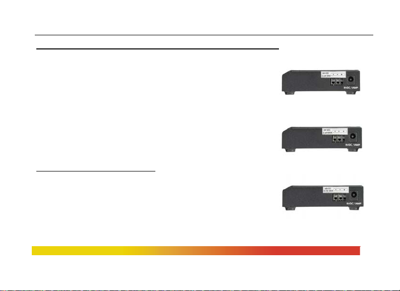
Direct DC POWER SUPPLY:
built-in terminal block for
+, -, ground along with 12VDC jack
12V DC internal (range of 8.0 to 15V DC)
24V DC internal (range of 18 to 36V DC).
-48V DC internal (range of 36 to 60V DC), -, ground

CSG14 Series Gigabit Converter Switch Installation and User Guide (05/09)
7
www GarrettCom com
..
Power Consumption: See Section 3.6.
Note 1: the 8-15V DC jack can be used for dual source DC input using an AC adapter and
the DC terminal block. Power supply protection is provided by internal diodes.
Note 2: The Direct DC power floats. The user may ground either “+” or “-” if desired.
Port Connectors (CSG14H / CSG14P
:
Two RJ-45 Ports: supports 10/100/1000Mbps with auto cross (MDIX).
They are shielded 8-pin female connectors for shielded (STP) and unshielded
(UTP) Cat 3, 4, 5 cables.
One Fiber optic port: The CSG14 series is 1000Base-SX / -LX / -ZX with a
“fiber flavor” choice of multimode or singlemode SC, SLC, SFP connectors.
Port Connectors (CSG14UH / CSG14UP
:
One RJ-45 Port: supports 10/100/1000Mbps with auto cross (MDIX).
It is shielded 8-pin female connector for shielded (STP) and unshielded (UTP)
Cat 3, 4, 5 cables.
Two Fiber optic ports: The CSG14U series is 100Base-FX or 1000Base-SX /-LX
/ -ZX with a “fiber flavor” choice of multimode or singlemode SFP connectors.

CSG14 Series Gigabit Converter Switch Installation and User Guide (05/09)
8
www GarrettCom com
..
Switches (CSG14H / CSG14P)
Fiber port default is FDX (Full-Duplex)
RJ45’s are triple-speed auto-negotiating
Switches (CSG14UH / CSG14UP)
Eac h SFP port is fa c t ory set to Gb speed
User may select 100Mb speed via DIP switch on the back of the unit
Eac h SFP port is individua lly speed-selectable
NOTE: After changing the speed switch setting, power cycle the unit for the speed
setting to take effect.
CSG14 Series Gigabit Converter Switch Installation and User Guide (05/09)
9
www GarrettCom com
..
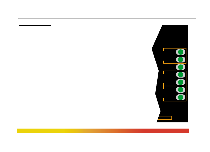
LED Indicators (Two sets) top-front and end with ports
Top-Front: (shown)
POWER: Steady ON when power applied
Gb per port: Steady ON for 1000Mbps; OFF for
100Mbps or 10Mb speed
LK/ACT per port: Steady ON for LINK (LK) with no
traffic, BLINKING for Activity
End with Ports:
POWER: Steady ON when power applied
10/100/Gb per RJ45 port: Steady ON for 100Mb,
OFF for 10Mb,
BLINKING for Gb
Fiber port: LK/ACT: Steady ON for Link with no
traffic, BLINKING for Activity
POWER
LK/ACT
Gb
LK/ACT
Gb
LK/ACT
PORT 1 PORT 2 PORT 3
PORT 3
Gb

CSG14 Series Gigabit Converter Switch Installation and User Guide (05/09)
10
www GarrettCom com
..
Mounting options
Metal mounting clips for panel mounting: included
DIN-Rail mounting option: Model # DIN-RAIL MC2 (see Section 3.4)
Rack-mount option: MC14-TRAY, see
http://www.garrettcom.com/mc_tray.htm
Mean Time Between Failure (MTBF) – over15 years, Telcordia (Bellcore) Method
Agency Approvals and Standards Compliance:
UL Listed (UL 60950), cUL, CE,
Emissions meets FCC Part 15 Class A.
NEBS L3 and ETSI compliant.
P model: IEEE P1613 Env. Std for Electric Power Substations
P model: NEMA TS-2 and TEES for traffic control equipment
P model: designed for UL 2043 above-the-ceiling installation
IEC61850 EMC and Operating Conditions Class C Power Substations
Warranty:
Three years, return to factory Made in USA

CSG14 Series Gigabit Converter Switch Installation and User Guide (05/09)
11
www GarrettCom com
..
1.2 Summary of models and descriptions:
CSG14H (Hardened Model) for 1000Mb fiber
CSG14H-ff-Hd, Hi = Hardened (H), two 10/100/1000Mb RJ-45+ one 1000Mb Fiber port for
factory floor (-25 to 60C) using a direct DC ( 8-15VDC) and/or external
AC hardened power supply (included).
CSG14H-ff-12VDC = Same as CSG14H model,
except AC hardened power supply is not included
CSG14H-ff-24VDC = Same as CSG14H-12VDC model,
except 24VDC power input replaces 12VDC.
CSG14HR-ff-24VDC = Same as CSG14H-24VDC model,
but includes DIN-RAIL-MC2 mounting option.
CSG14H-ff-48VDC = Same as CSG14H-24VDC m odel,
except -48VDC power input replaces 24VDC

CSG14 Series Gigabit Converter Switch Installation and User Guide (05/09)
12
www GarrettCom com
..
CSG14P (Premium Model) for 1000Mb fiber
CSG14P-ff-Pd, Pi = Premium (P), two 10/100/1000Mb RJ-45+ one 1000Mb Fiber port for un-
controlled(outdoor) (-40 to 75C) using direct DC (8-15VDC) and/or
external AC premium power supply (included).
CSG14P-ff-12VDC = Same as CSG14P-Pd, Pi, except AC Premium Power Supply is not
included.
CSG14P-ff-24VDC = Same as CSG14P-12VDC model,
except 24VDC power input replaces 12VDC.
CSG14PR-ff-24VDC = Same as CSG14P-24VDC model,
but includes DIN-RAIL-MC2 mounting option.
CSG14P-ff-48VDC = Same as CSG14P-24VDC model, except -48VDC input replaces 24VDC.
Fiber Port Connectors (CSG14H / CSG14P):
The “ff” field is for selection of the desired “fiber flavor” as listed below.
“SX” = 1000Base-SX-SC: 850nm multi-mode fiber optic with SC type connector, 550 m.
“ESX”= 1000Base-SX Extended: 1310nm multi-mode fiber optic with SC type connector, 2 km
“LX10”= 1000Base-LX-SLC: 1310nm single-mode fiber optic with L C type connector, 10 km

CSG14 Series Gigabit Converter Switch Installation and User Guide (05/09)
13
www GarrettCom com
..
“LX25” = 1000Base-LX-SLC: 1310nm single-mode fiber optic with LC type connector, 25 km
“ZX40” = 1000Base-ZX-SLC: 1550nm single-mode fiber optic with LC type connector, 40 km
“ZX70”= 1000Base-ZX-SLC: 1550nm single-mode fiber optic with LC type connector, 70 km
“SFP” = open SFP transceiver slot in the fiber position. (order SFP as a separate item)
“SFP-SX”= 1000Base-SX-LC: 850nm multi-mode SFP, 550 m
“SFP-ESX”= 1000Base-SX Extended: 1310nm multi-mode fiber optic with LC type connector, 2 km
“SFP-LX10”= 1000Base-LX-SLC: 1310nm single-mode SFP, 10 km
“SFP-LX25”= 1000Base-LX-SLC: 1310nm single-mode SFP, 25 km
“SFP-ZX40”= 1000Base-ZX-SLC: 1550nm single-mode SFP, 40 km
“SFP-ZX70”= 1000Base-ZX-SLC: 1550nm single-mode SFP, 70 km
CSG14UH (Hardened Model) for 1000Mb fiber
CSG14UH-ff-Hd, Hi = Hardened ( H ), one 10/100/1000Mb RJ-45+ two 1000Mb Fiber ports for
factory floor (-25 to 60C) using a direct DC ( 8-15VDC) and/or external
AC hardened power supply (included).
CSG14UH-ff-12VDC = Same as CSG14UH model,
except AC hardened power supply is not included
CSG14UH-ff-24VDC = Same as CSG14UH-12VDC model,

CSG14 Series Gigabit Converter Switch Installation and User Guide (05/09)
14
www GarrettCom com
..
except 24VDC power input replaces 12VDC.
CSG14UHR-ff-24VDC = Same as CSG14UH-24VDC model,
but includes DIN-RAIL-MC2 mounting option.
CSG14UH-ff-48VDC = Same as CSG14UH-24VDC model,
except -48VDC power input replaces 24VDC
CSG14UP (Premium Model) for 1000Mb fiber
CSG14UP-ff-Pd, Pi = Premium (P), one 10/100/1000Mb RJ-45+ two 1000Mb Fiber ports for un-
controlled(outdoor) (-40 to 75C) using direct DC (8-15VDC) and/or
external AC premium power supply (included).
CSG14UP-ff-12VDC = Same as CSG14UP-Pd, Pi, except AC Premium Power Supply is not
included.
CSG14UP-ff-24VDC = Same as CSG14UP-12VDC model,
except 24VDC power input replaces 12VDC.
CSG14UPR-ff-24VDC = Same as CSG14UP-24VDC model,
but includes DIN-RAIL-MC2 mounting option.
CSG14UP-ff-48VDC = Same as CSG14UP-24VDC model, except -48VDC input replaces 24VDC

CSG14 Series Gigabit Converter Switch Installation and User Guide (05/09)
15
www GarrettCom com
..
Fiber Port Connectors (CSG14UH / CSG14UP):
The “ff” field is for selection of the desired “fiber flavor” as listed below.
“SFP” = open SFP transceiver slot in the fiber position. (order SFP as a separate item)
“SFP-SX”= 1000Base-SX-LC: 850nm multi-mode SFP, 550 m
“SFP-ESX”= 1000Base-SX Extended: 1310nm multi-mode fiber optic with LC type connector, 2 km
“SFP-LX10”= 1000Base-LX-SLC: 1310nm single-mode SFP, 10 km
“SFP-LX25”= 1000Base-LX-SLC: 1310nm single-mode SFP, 25 km
“SFP-ZX40”= 1000Base-ZX-SLC: 1550nm single-mode SFP, 40 km
“SFP-ZX70”= 1000Base-ZX-SLC: 1550nm single-mode SFP, 70 km
“SFP100P-FXMM2”= 100Base-FX, multi-mode SFP, 2Km
“SFP100P-FXSM15”= 100Base-FX, single-mode SFP, 15Km
“SFP100P-FXSM40”= 100Base-FX, single-mode SFP, 40Km
Accessories
MC14-TRAY = 19” Rack-mount tray for 14-series Switch models, up to 16 units
Other Tray configurations with power supplies and power cabling included - See Section 3.3
DIN-RAIL-MC2 = Metal DIN-Rail mounting bracket for one CSG14 Series Switch,
See Section 3.4
Conformal Coating (for high humidity and “tropical” applications) - re quest quote.

CSG14 Series Gigabit Converter Switch Installation and User Guide (05/09)
16
www GarrettCom com
..
2.0 INTRODUCTION
This section describes CSG14 Series models, including appearance, features and
typical applications.
2.1 Inspecting the Package and the Product
Examine the shipping container for obvious damage prior to installing this
product; notify the carrier immediately of any damage, which you believe occurred during
shipment or delivery. Inspect the contents of this package for any signs of damage and
ensure that the items listed below are included.
This package should contain:
1 Magnum CSG14 Series Converter Switch unit,
1 External Power Supply, (for -Hd, -Hi, -Pd and -Pi models only)
1 set Metal panel mounting clips and screws (2 each)
1 User Guide (this manual)
 Loading...