


INSTALLATION, OPERATING & SERVICE INSTRUCTIONS FOR THE GARLAND ELECTRIC XPRESS GRILL, MODELS XE24, XE36
FOR YOUR SAFETY
DO NOT STORE OR USE GASOLINE OR OTHER FLAMMABLE VAPORS OR LIQUIDS IN THE VICINITY OF THIS OR ANY OTHER APPLIANCE.
WARNING:
IMPROPER INSTALLATION, ADJUSTMENT, ALTERATION, SERVICE OR MAINTENANCE CAN CAUSE PROPERTY DAMAGE, INJURY OR DEATH. READ THE INSTALLATION, OPERATION AND MAINTENANCE INSTRUCTIONS THOROUGHLY BEFORE INSTALLING OR SERVICING
THIS EQUIPMENT.
PLEASE READ ALL SECTIONS OF THIS MANUAL AND RETAIN FOR FUTURE REFERENCE.
THIS PRODUCT HAS BEEN CERTIFIED AS COMMERCIAL COOKING EQUIPMENT AND MUST BE INSTALLED BY PROFESSIONAL PERSONNEL AS SPECIFIED.
For Your Safety:
Post in a prominent location, instructions to be followed in the event the user smells gas. This information shall be obtained by consulting your local gas supplier.
Users are cautioned that maintenance and repairs must be performed by a Garland authorized service agent using genuine Garland replacement parts. Garland will have no obligation with respect to any product that has been improperly installed, adjusted, operated or not maintained in accordance with national and local codes or installation instructions provided with the product, or any product that has its serial number defaced, obliterated or removed, or which has been modified or repaired using unauthorized parts or by unauthorized service agents. For a list of authorized service agents, please refer to the Garland web site at http://www.garland-group.com. The information contained herein, (including design and parts specifications), may be superseded and is subject to change without notice.
Continuous product improvement is a Garland policy, therefore design and specifications are subject to change without notice.
GARLAND COMMERCIAL INDUSTRIES |
GARLAND COMMERCIAL RANGES, |
Enodis UK LTD. |
|
185 East South Street |
LTD. |
Swallowfield Way, Hayes, Middlesex UB3 1DQ ENGLAND |
|
Freeland, Pennsylvania 18224 |
1177 Kamato Road, Mississauga, Ontario L4W 1X4 |
Telephone: 081-561-0433 |
|
Phone: (570) 636-1000 |
Fax: 081-848-0041 |
||
CANADA |
|||
Fax: (570) 636-3903 |
|
||
Phone: 905-624-0260 |
|
||
|
|
||
|
Fax: 905-624-5669 |
|
Part # 4517125 (09/03) |
© 2003 Garland Commercial Industries, Inc. |
INTRODUCTION
The Garland Xpress Grill provides a method for e cient two-sided cooking, while accommodating a variety of products. The unit will also serve as a flat grill, and meets all standards for safety, e ciency, and cleanliness.
Standard Features:
•Stainless steel front, top & sides
•4.3kW input for each twelve-inch section of griddle
•208V/240V, three phase or 400V, three phase top heaters
•¾" thick, Carbon steel griddle plate, machine ground, highly polished
•Swivel casters complete with front brakes (4)
•Die cast aluminum electric top heating elements rated 208V, 240V or 400V
•Automatic lifting and lowering top heaters
•Towel bar with bun pan lip
•Stainless steel dual side grease collectors
•Separate programmable controller for each twelve-inch section
•Multi-colored LED indicator lights to identify operational mode
•One year limited parts and labor warranty (USA & Canada)
Page 2 |
Part # 4517125 (09/03) |

TABLE OF CONTENTS
Introduction........................................................... |
2 |
Standard Features: ............................................................ |
2 |
Dimensions & Specifications, XE18....................... |
4 |
Dimensions & Specifications, XE24 ...................... |
5 |
Safety Precautions.................................................. |
6 |
Installation............................................................. |
7 |
National Codes Requirements: ......................................... |
7 |
Electrical Connections:..................................................... |
8 |
Grill Controls ........................................................ |
8 |
Master Power Switch: ....................................................... |
8 |
Indicator Lights:................................................................ |
8 |
Display: ............................................................................ |
8 |
Gap Setting Buttons (1-5):................................................ |
8 |
Gap Button:...................................................................... |
8 |
Power Button:................................................................... |
9 |
Program Button:............................................................... |
9 |
Temperature Button:......................................................... |
9 |
Up/Down Arrow Buttons; 2 Functions: ........................... |
9 |
Enter Button:.................................................................... |
9 |
Cancel/Raise Platen Button, (Green): .............................. |
9 |
Black Button: ................................................................... |
9 |
Operation ............................................................ |
10 |
Installing Release Material:............................................. |
10 |
Lighting Instructions:..................................................... |
11 |
To Cook in Two-Sided Mode:......................................... |
11 |
To Perform and Additional Cook Cycle:......................... |
11 |
To Cook in Flat Grill Mode:........................................... |
11 |
Enter Standby Mode:...................................................... |
12 |
Exit Standby Mode:........................................................ |
12 |
To Display the Current Temperatures:............................ |
12 |
To View Settings for a Menu Item: ................................. |
12 |
To Clean the Grill:.......................................................... |
12 |
Cleaning & Maintenance..................................... |
13 |
Cleaning During Operation:........................................... |
13 |
Daily Cleaning:............................................................... |
13 |
Platen Zeroing:................................................................ |
14 |
Programming....................................................... |
16 |
Programming Modes/Menu Sequence:........................... |
16 |
Menu Items |
|
To Change the Cook Time of a Product:........................ |
18 |
To Turn Platen, (2-Sided), Cooking On/O : ................. |
18 |
To Change Upper Platen Set Temperature:..................... |
18 |
To Change Grill Set Temperature:.................................. |
18 |
To Change a Product Name:........................................... |
19 |
System Info |
|
To View Recovery Time - Upper Platen:......................... |
19 |
To View Recovery Time - Grill:...................................... |
19 |
To View the Garland Part Number:................................ |
20 |
To View the Flash Number:............................................ |
20 |
To View the Software Number: ...................................... |
20 |
To View the Download Number:.................................... |
20 |
System Setup |
|
To Change temperature Units, (°F or °C): ...................... |
21 |
To Change Gap Setting Display Units:........................... |
21 |
To Change the Alarm Volume:....................................... |
21 |
To Change Probe Calibration - Upper:........................... |
21 |
To Change Probe Calibration - Grill:.............................. |
22 |
To Change Platen Set:..................................................... |
22 |
To Change Instant-On Time:......................................... |
22 |
To Change Control Type:............................................... |
23 |
To Turn Extended Time On/O :................................... |
23 |
To Change the Grill Function:........................................ |
23 |
To Change the Start Delay:............................................. |
23 |
To Change the Alarm Mode:.......................................... |
24 |
To Turn Clean Mode On/O :........................................ |
24 |
Service Mode |
|
To Change SCK Address:................................................ |
24 |
To Perform Limit Switch Test:........................................ |
25 |
Gap Button |
|
To Change Gap Setting: ................................................. |
25 |
Calibration........................................................... |
26 |
Bi-Weekly Calibration:.................................................... |
26 |
Probe Locations: ............................................................. |
27 |
Troubleshooting................................................... |
28 |
Error Messages |
|
PROBE ERROR:............................................................ |
28 |
PLATEN DOWN ERROR:........................................... |
28 |
PLATEN UP ERROR:................................................... |
28 |
HEATING ERROR:...................................................... |
28 |
COMM ERROR:........................................................... |
28 |
MOTOR OVER CURRENT: ....................................... |
28 |
MOTOR ERROR:......................................................... |
28 |
Wiring Diagrams................................................. |
29 |
Part # 4517125 (09/03) |
Page 3 |
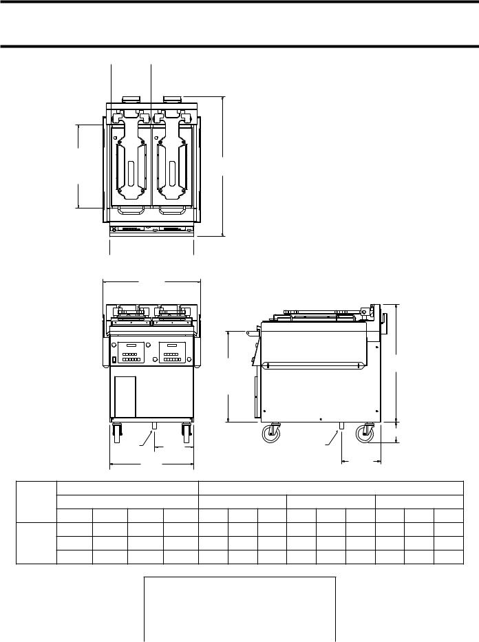
DIMENSIONS AND SPECIFICATIONS, MODEL XE24
11-1/2"  (292mm)
TOP
HEATER TOP VIEW (2 PLACES)
24" |
|
|
(610mm) |
40-1/4" |
|
GRILL |
||
(1022mm) |
||
PLATE |
||
|
||
DEPTH |
|
24"
 (610mm)
  GRILL PLATE WIDTH
28-3/16" (716mm)
|
|
|
|
|
26-1/8" |
|
|
|
|
33-3/4" |
|
|
|
|
|
|
|
|
|
|
|
|
(858mm) |
|
|
||
|
|
|
|
|
(663mm) |
|
|
|
|
|
|
||
|
|
|
|
|
|
|
|
|
|
|
|
||
|
|
|
|
|
GRILL |
|
|
|
|
|
|
|
|
|
|
|
|
|
PLATE |
|
|
|
|
|
|
|
|
|
|
|
|
|
HEIGHT |
|
|
|
|
|
|
|
|
|
|
|
FRONT VIEW |
|
|
|
RIGHT SIDE VIEW |
|
|
|
|
||
|
|
|
|
|
|
|
|
|
|
|
6" (152mm) |
|
|
|
|
|
GAS |
11-1/4" |
|
|
|
GAS |
|
|
|
|
|
|
|
|
INLET |
(286mm) |
|
|
|
INLET |
11-3/16" |
|
|
|
|
|
|
|
|
|
|
|
|
|
|
|
|
||
|
|
|
24-1/8" |
|
|
|
|
|
|
(285mm) |
|
|
|
|
|
|
|
|
|
|
|
|
|
|
|
|
|
|
|
|
(614mm) |
|
|
|
|
|
|
|
|
|
|
|
|
Loading kW Per Phase |
|
|
|
Nominal Amps Per Line |
|
|
|
||||
Model |
|
208/220/240V 3-Phase |
208V 3-Phase Delta |
220V 3-Phase Delta |
240V 3-Phase Delta |
||||||||
|
* |
X-Y |
X-Z |
Y-Z |
X |
Y |
Z |
X |
Y |
Z |
X |
Y |
Z |
|
TB1 |
3.67 |
4.00 |
3.67 |
32.03 |
30.70 |
32.03 |
30.28 |
29.02 |
30.28 |
27.76 |
26.60 |
27.76 |
XE24 |
TB2 |
1.84 |
1.84 |
1.84 |
15.43 |
15.43 |
15.43 |
14.60 |
14.60 |
14.60 |
13.38 |
13.38 |
13.38 |
|
CAN |
5.51 |
5.84 |
5.51 |
47.46 |
46.13 |
47.46 |
44.88 |
46.62 |
44.88 |
41.14 |
39.98 |
41.14 |
* TB1 and TB2 are for dual supply units for the USA only.
CAN is for single supply units, typically used in Canada only.
Clearances
Entry |
Installation |
||
|
|
|
|
Crated |
Uncrated |
Sides |
Rear |
|
|
|
|
47-1/2" |
32" |
6" |
3" |
(1207mm) |
(813mm) |
(152mm) |
(76mm) |
|
|
|
|
Page 4 |
Part # 4517125 (09/03) |

DIMENSIONS AND SPECIFICATIONS, MODEL XE36
11-1/2" (292mm)
 TOP
TOP 
HEATER TOP VIEW (3 PLACES)
24" |
|
(610mm) |
38-1/2" |
GRILL |
|
PLATE |
(978mm) |
DEPTH
36" (914mm)
GRILL PLATE WIDTH
40-3/16" (1021mm)
|
|
|
|
|
|
26-3/16" |
|
|
|
|
33-7/8" |
|
|
|
|
|
|
|
|
|
|
|
|
(861mm) |
|
||
|
|
|
|
|
|
(665mm) |
|
|
|
|
|
||
|
|
|
|
|
|
|
|
|
|
|
|
||
|
|
|
|
|
|
GRILL |
|
|
|
|
|
|
|
|
|
|
|
|
|
PLATE |
|
|
|
|
|
|
|
|
|
|
|
|
|
HEIGHT |
|
|
|
|
|
|
|
|
|
|
FRONT VIEW |
|
|
|
RIGHT SIDE VIEW |
|
|
|
|||
|
|
|
|
|
|
|
|
|
|
|
|
6" (152mm) |
|
|
|
|
36-5/32" |
|
|
|
|
|
|
|
|
|
|
|
|
|
(918mm) |
|
|
|
|
|
|
|
|
|
|
|
|
Loading kW Per Phase |
|
|
|
|
Nominal Amps Per Line |
|
|
|
|||
Model |
|
208/220/240V 3-Phase |
|
208V 3-Phase Delta |
220V 3-Phase Delta |
240V 3-Phase Delta |
|||||||
|
* |
X-Y |
X-Z |
Y-Z |
X |
Y |
Z |
X |
Y |
Z |
X |
Y |
Z |
|
TB1 |
5.53 |
6.01 |
5.53 |
48.04 |
46.04 |
48.04 |
45.42 |
46.53 |
45.42 |
41.64 |
39.90 |
41.64 |
XE24 |
TB2 |
2.78 |
2.78 |
2.78 |
23.14 |
23.14 |
23.14 |
21.88 |
21.88 |
21.88 |
20.06 |
20.06 |
20.06 |
|
CAN |
8.31 |
8.79 |
8.31 |
71.18 |
69.18 |
71.18 |
67.30 |
65.41 |
67.30 |
61.70 |
59.96 |
61.70 |
* TB1 and TB2 are for dual supply units for the USA only.
CAN is for single supply units, typically used in Canada only.
Clearances
Entry |
Installation |
||
|
|
|
|
Crated |
Uncrated |
Sides |
Rear |
|
|
|
|
47-1/2" |
32" |
6" |
3" |
(1207mm) |
(813mm) |
(152mm) |
(76mm) |
|
|
|
|
Part # 4517125 (09/03) |
Page 5 |

SAFETY PRECAUTIONS
Always follow these safety precautions when operating the Xpress Grill.
•THIS GRILL MUST be operated by persons who have been given adequate training.
•THIS EQUIPMENT MUST ONLY BE OPERATED UNDER AN APPROVED HOOD SYSTEM.
•DO NOT operate the grill without reading this operation manual.
•DO NOT operate the Xpress grill unless all service and access panels are in place and fastened properly.
The Garland Xpress Grill is a semi-automatic cooking appliance. The upper platen is lowered automatically, following the manual, two-handed initiation of the cookingcycle,andtheupperplatenisraisedautomatically upon completion of the cooking cycle.
When two sided cooking, the area between the upper platen and the griddle plate should be regarded as a “danger zone.” During two sided cooking the operator must not be within this danger zone. When used as a flat grill, then this area is no longer a danger zone, the platens do not move.
For whatever reason, be it cleaning, maintenance, or normaloperation,anyexposedpersonmustuseextreme caution if within this danger zone.
In two side cooking the upper platen remains in the lowered position by nature of its own weight. It is not lockeddown.Itcanberaisedbyliftinguponthehandle on the front of the platen.
TheXpressGrillmayduringitsoperationemitairborne noise equivalent to a continuous A weighted sound pressure level of 73dB(A).
WARNING: To avoid serious personal injury:
•DO NOT attempt to repair or replace any part of the Xpress Grill unless all main power supplies to the grill have been disconnected.
•USE EXTREME CAUTION in setting up, operating and cleaning the Xpress Grill to avoid coming in contact with hot grill surfaces or hot grease. Suitable protective clothing should be worn to prevent the risk of burns.
•DO NOT clean this appliance with a water jet.
•DO NOT apply ICE or COLD WATER to a HOT grill surface.
•NOTE all warning labels and markings a xed to the grill.
WARNING: After turning the master power switch to the START position, the grill will go through initialization. If the upper platens are in the lowered position they will return to their raised upper position. This movement takes approximately 8 seconds.
Page 6 |
Part # 4517125 (09/03) |

INSTALLATION
IMPORTANT: Rating plates for this appliance are located in two places: 1) inside back panel on left side, 2) under front control panel on center.
Thisequipmentmustbeinstalledbyacompetentfactory trained,certified,licensedand/orauthorizedserviceor installation person.
WARNING: This appliance must be properly grounded.
Priortoinstallation,thefourcasters,suppliedloosewith the grill, must be securely located on the underside of thebase.Thecastersfittedwithabrakemustbelocated at the front of the grill.
This appliance should be connected to a potential equalization system. A labeled equipotential bonding point is fitted to the rear of the grill.
It is recommended that this grill be connected to a residualcurrent,,(earthleakage),,devicewithatripping currentnotexceeding30mA.Theleakagecurrentofthis grill will not exceed 5mA.
CAUTION: Prior to installation, check the electrical supply to ensure input voltage and phase match the equipment voltage rating and phase. See data plate located rear left side of grill and lower front panel.
Grill is to be located directly under ventilation system.
Once installed in the grill station underneath the ventilationsystem,theplatens,intheirhighestposition, must not interfere with the lower lip of the ventilation system hood. The raised position of each platen is adjusted by raising or lowering the upper of the two microswitches, (limit switches), in the rear of the grill. The lower microswitch position must not be adjusted.
Grill plate must be level front to back, side to side and diagonally. This leveling must be done with the unit under the hood and in it’s normal operational position to prevent warping of the grill plate.
NOTE: Fuses are installed to prevent damage in the event of failure of the upper microswitch.
National Codes Requirements:
In Canada, electrical connection must comply with applicable sections of the Canadian Electrical Code, C22.1 - 1990, latest edition, “Safety Standard for Installation, Part 1” and C22.2- No. O-M 1982 latest edition , “General Requirements, Part 2”.
Electrical Connections:
All electrically operated appliances must be electrically grounded in accordance with local codes; or in the absenceoflocalcodes,withthelatesteditionofNational WiringRegulations.Awiringdiagramislocatedonthe rear panel of the grill. See rating plate in rear of grill, or lower front panel for proper voltages.
Part # 4517125 (09/03) |
Page 7 |
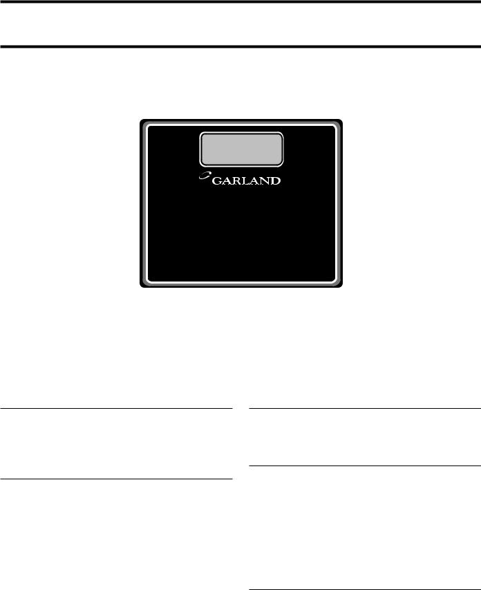
GRILL CONTROLS
WHEN PUSHED SIMULTANEOUSLY:
COOK TIME COUNTDOWN" (flat grill
R "LOWER PLATEN" (two-sided cookin
READY
INDICATO
CANCEL/ |
|
GAP |
|
RAISE PLATEN |
|
SETTING |
|
BUTTON |
|
BUTTONS |
|
|
|
GAP |
|
ON |
|
BUTTON |
|
|
|
||
OFF |
|
|
|
|
POWER |
ENTER |
|
MASTER BUTTON |
BUTTON |
||
POWER |
PROGRAM |
DOWN ARROW |
|
SWITCH |
|||
BUTTON |
BUTTON |
||
|
|||
|
TEMPERATURE |
UP ARROW |
|
|
BUTTON |
BUTTON |
|
Master Power Switch:
Controls power to the grill and must be turned “ON” to start operation. The controller display will be active when the switch is “ON”.
Indicator Lights:
There are two, (2), indicator lights, indicating the temperature status of each control’s heat zones; one, (1), on the upper platen, (top light), and one, (1), on the grill surface. Each light can display three, (3), di erent colors, indicating temperature status for the corresponding zone.
Red: The zone is too hot, (more than 79°F/45°C over the set temperature), or heat zone failure.
Amber: The zone is calling for heat.
Green: The zone is at or above the set temperature.
Display:
Thecontrollerdisplaywillcontaininformationrelevant to each operation in both cook and program modes.
Gap Setting Buttons (1-5):
For two-sided recipes, the desired gap button is pressed beforethecookcyclebeginstosetthegap.Holdbuttons 1-5 to apply gap settings 6-10. The chosen gap button and its value will be displayed. Until a di erent menu itemisselected,(orthecurrentitemischangedandthen returned to), the Gap Button only needs to be pressed before the initial cook.
Gap Button:
When in programming mode, press the Gap Button to setthevaluesforGapButtons1-10.PressEntertoaccept thechanges.Aftergoingthroughallten,youwillreturn to Programming Mode.
Page 8 |
Part # 4517125 (09/03) |

GRILL CONTROLS continued
Power Button:
After the main power switch is turned on, this button will put the control into cook mode. If pressed again, the control will go back to displaying “OFF.”
Program Button:
The primary function is to access Programming and Calibrationofthegrill.Pushandholdforfive(5)seconds. Display will ask for the code. After entering code, four programming features will be accessible “MENU ITEMS,”“SYSTEMINFO,”“SYSTEMSETUP,”and “SERVICE MODE.”
Temperature Button:
In the Cook mode, each time the button is pressed the current temperature for one zone will be displayed. The grill temperature is displayed first followed by the platen temperature. After five (5) seconds, the display will return to the menu item selected.
Up/Down Arrow Buttons; 2 Functions:
1.In the cook mode, the Up/Down Arrow Buttons will cycle through the di erent menu items.
2.Intheprogrammode,theUp/DownArrowButtons will change the value of the current setting.
Enter Button:
Function is to accept programming steps.
Cancel/Raise Platen Button, (Green):
During the cooking cycle, pressing this button will cancel the cooking timer and return the grill to the “IDLE” mode. This button will also bring the grill out of STANDBY.
Black Button:
When both Black and Green “CANCEL/RAISE” buttons are pressed simultaneously, the upper platen will lower to the griddle surface.
Part # 4517125 (09/03) |
Page 9 |
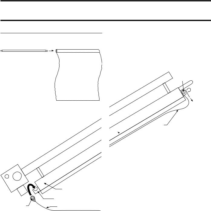
OPERATION
Installing Release Material:
Slide release material rod through hemmed end of the release material sheet.
around the top and down over the front of the bar as shown.
Place locking clips over release material sheet and press into place over release material bar.
RELEASE
MATERIAL
BAR RELEASE
MATERIAL
LOCKING
 CLIP (1)
Hookreleasematerialrodonbracketslocatedattherear of the upper plate
RELEASE
MATERIAL
 UPPER PLATEN (side view)
FRONT OF GRILL 
|
UPPER PLATEN (side view) |
|
RELEASE MATERIAL HOOK |
RELEASE |
RELEASE MATERIAL SHEET |
MATERIAL ROD |
|
 REAR OF GRILL
Holdingthebottomofthereleasematerialsheetinplace, gently pull the sheet toward the front of the platen.
Threadthefrontedgeofthereleasematerialsheetbehind the release material bar on the front of the platen, then
Checkalignmentandtightnessofreleasematerialagainst upper platen.
NOTE: Make sure release material fits smoothly over upper platen. Installing release material sheets too tight may cause premature failure of the sheet.
Release sheets are reversible and should be flipped over and reattached on a daily basis. For instructions on cleaning release sheets, see Step 17., at top of Page 15.
A release material sheet must be replaced when:
•Product sticks to release material.
•Carbon build-up causes problems in taste or appearance.
•Tearing occurs in the sheet’s cooking area.
•Release material coating is worn o sheet.
Page 10 |
Part # 4517125 (09/03) |
 Loading...