


TS-331A

WIRED TRAWL SONAR
TS-331A

Thepaperusedinthismanual
iselementalchlorinefree.
Your Local Agent/Dealer Your Local Agent/Dealer
9-52 Ashihara-cho,9-52 Ashihara-cho,
Nishinomi
y
a 662-8580, JAPANNishinomi
y
a 662-8580, JAPAN
Tele
p
hone :Tele
p
hone : 0798-65-21110798-65-2111
FaxFax 0798-65-42000798-65-4200
::
IRST EDITION :
IRST EDITION : JANJAN.. 20052005
Printed in JapanPrinted in Japan
A
ll ri
g
hts reserved.
A
ll ri
g
hts reserved.
Pub. No.Pub. No. OME-13210OME-13210
*
00015138400
*
*
00015138400
*
*
00015138400
*
*
00015138400
*
(( DAMIDAMI ))
TS-331ATS-331A
* 0 0 0 1 5 1 3 8 4 0 0 ** 0 0 0 1 5 1 3 8 4 0 0 *
*
OME
13210
A
00
*
*
OME
13210
A
00
*
*
OME
13210
A
00
*
*
OME
13210
A
00
*
* O M E 1 3 2 1 0 A 0 0 ** O M E 1 3 2 1 0 A 0 0 *
i
SAFETY INSTRUCTIONS
Do not place liquid-filled containers on
the top of the surface processor unit.
Fire or electrical shock can result if a liquid
spills into the unit.
Immediately turn off the power at the
switchboard if the surface processor
unit is emitting smoke or fire.
Continued use can cause fatal damage to
the equipment. Contact a FURUNO
agent for service.
Make sure no rain or water splash leaks
into the surface processor unit.
Fire or electrical shock can result if water
leaks in the unit.
Use the proper fuse.
Use of a wrong fuse can result in damage
to the equipment or cause fire.
Use the proper battery in the surface
processor unit.
The mother board in the surface processor
unit has a battery which stores settings
when the power is off. Use the correct
battery and install it properly to prevent
explosion of the battery.
WARNING
Do not disassemble or modify the
equipment.
Fire, electrical shock or serious injury can
result.
Immediately turn off the power at the
switchboard if water leaks into the
surface processor unit.
Continued use of the equipment can cause
fire or electrical shock. Contact a FURUNO
agent for service.
Install batteries in the catch sensor with
correct polarity.
Improper polarity or size may cause the
batteries to explode.
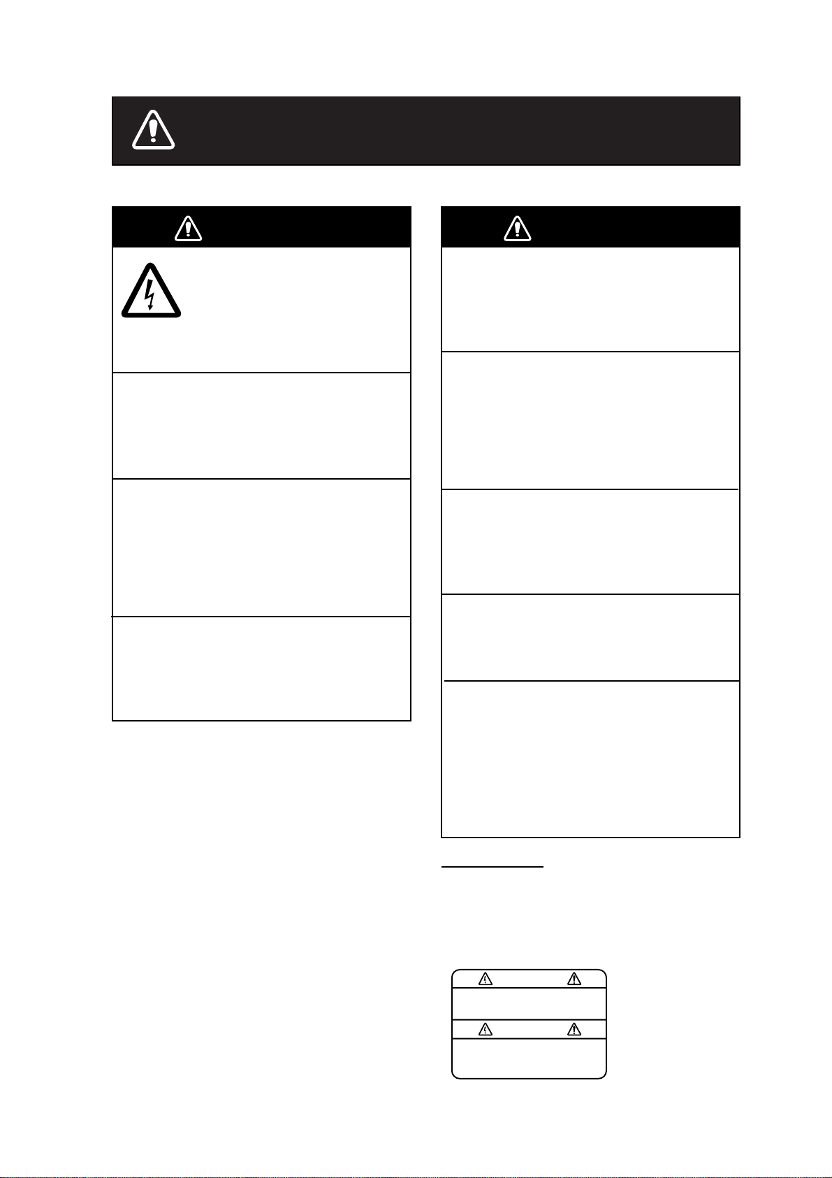
WARNING
ELECTRICAL SHOCK HAZARD
Do not open the surface
processor unit.
Only qualified personnel should
work inside the equipment.
A warning label is attached to the surface
processor unit. Do not remove the label.
If the label is missing or damaged,
contact a FURUNO agent or dealer about
replacement.
WARNING
To avoid electrical shock, do not
remove cover. No user-serviceable
parts inside.
Name: Warning Label (1)
Type: 86-003-1011-1
Code No.: 100-236-231
WarningLabel

ii
TABLE OF CONTENTS
FOREWORD...........................................iii
SYSTEM CONFIGURATION ...................iv
OPERATIONAL INFORMAT ION ..............v
1. OPERATIONAL OVERVIEW.................1
1.1
Surface Processor Unit...........................1
1.2
Underwater Unit......................................2
1.2.1 Components of the underwater
unit...........................................2
1.2.2 Trawl system............................2
1.2.3 Mounting the underwater unit
on the trawl...............................3
1.3
St arting U p, Sh utting Dow n.....................4
1.3.1 Starting up................................4
1.3.2 Shutting down ..........................4
1.4
Catch Sensor CS-400 (option)................5
1.5
Screen Layout......................................... 6
1.5.1 Menu bar .................................. 7
1.5.2 Toolbars...................................7
1.6
Display Indications..................................9
1.7
Pop-up Windows................................... 10
2. SONAR OPERATION ......................... 11
2.1
Choosing a Sonar Mode........................11
2.1.1 Polar mode ............................ 11
2.1.2 Sector mode...........................12
2.1.3 Locked mode.........................13
2.2
Adjusting the Sonar Image from the
Vertical Sonar Settings Dialog Box........ 14
2.2.1 Choosing the display range ....14
2.2.2 Adjusting gain ........................ 15
2.2.3 Choosing train angl e ..............15
2.2.4 Choosing scan sector............. 15
2.2.5 Choosing scanning speed ...... 15
2.2.6 Choosi ng s onar frequency......15
2.2.7
Freezing th e dis p lay...............15
2.2.8
Reversi ng the scan direction .. 15
2.3
Monitoring Trawl Position...................... 16
2.4
Drawing Lines and Symbols................. 18
2.4.1 Drawing a symbol...................18
2.4.2 Drawing a l i ne........................ 18
2.4.3 Choosing line/symbol c olor..... 19
2.4.4 Clearing line/symbol art..........19
2.5
Findi ng Range and Be aring from Own
Ship to a Point........................................ 20
2.6
Zoom..................................................... 20
2.7
Choosing Display Color........................ 21
2.8
Grid....................................................... 22
2.9
Unit of Depth, Range Measurement..... 23
2.10
Noise Filter............................................ 23
2.11
Recording Sonar Data.......................... 24
2.12
Playing Back Sonar Data...................... 24
2.13
Saving, Loading System Configuration.26
2.13.1 Saving system confi guration...26
2.13.2 Loading system configuration. 26
3. ECHO SOUNDER OPERATION......... 27
3.1
Echo Sounder Image............................27
3.2
Adjusting the Echo Sounder Image
from the Sounder Settings Dialog Box... 28
3.2.1 Choosing the display range ....28
3.2.2 Adjusting data gain.................28
3.2.3 Adjusting echo sounder gai n ..28
3.2.4 Freezing the dis p lay...............28
3.3
Using the Echo Sounder Image to
Monitor Trawl Location...........................29
3.4
Drawing Lines and Symbols..................30
3.5
Grid........................................................30
3.6
Zoom.....................................................30
3.7
Colors....................................................30
4. DEPTH/TEMPERATURE DISPLAY.... 31
4.1
Unit of Temper at ur e, D e pt h
Measurement..........................................31
4.2
Setting Depth/Temperature Limits.........32
4.3
Depth/Temperature Offset..................... 32
4.4
Depth/Temperature Scale Text Size......33
5. MENU DESCRIPTION........................ 35
5.1
File Menu...............................................35
5.2
View Menu.............................................36
5.3
Communication Menu...........................37
5.4 Sonar Menu...........................................37
5.5
Options Menu........................................38
5.6
Help Menu.............................................39
6. CATCH SENSOR OPERATION.......... 41
6.1
Catch Sensor Dialog Box......................41
6.2
Catch Sensor Window...........................42
6.3
Testing for Switch Activ ation..................43
6.4
Flashing LED Sequence .......................43
6.5
Catch Sensor Transmission Frequency 43
6.6
Installing the Batteries and O-ring.........44
7. MAINTENANCE &
TROUBLESHOOTING........................... 47
7.1
General Maintenance............................47
7.2
Replacement of Fuse............................47
7.3 Replacement of Internal Battery............48
7.4
Testing the Underwater Unit..................48
7.5
Troublesho oting.....................................50
7.6
Diagnostic Test......................................51
7.6.1 Executing the diagnostic test.. 51
7.6.2 Diagnostic test description......52
MENU TREE..........................................53
SPECIFIC ATIONS.............................. SP-1
INDEX..................................................IN-1

iii
FOREWORD
Introduction
FURUNO Electric Company thanks you for
considering and purchasing the TS-331A
Wired Trawl Sonar. We are confident you
will discover why the FURUNO name has
become synonymous with qualit y and
reliability.
The TS-331A is a wired trawl monitoring
system designed to improve control and
efficiency in pelagic and semi-bottom
trawling. Mainly consisting of an
Underwater Unit, a Surface Processor Unit
and a Mouse, the TS-331A presents data
received from a trawl-mounted transducer
on high quality and low-noise images.
No machine can perform to the utmost of its
ability unless properly installed, maintained
and operated. Please read and follow the
recommended procedures for operation
and maintenance to get the most out of the
equipment.
Features
The TS-331A is a third wire, head rope
mounted system incorporating a high
resolution scanning sonar designed
especially for monitoring the opening of the
trawl net and surrounding areas. Also
included are depth and tem perature
sensors, a 120kHz downward looking echo
sounder, four catch indicators, and a pitch
and roll indicator for monitoring the attitude
of the trawl unit. The trawl unit is connected
to the Surface Processor Unit by a
2-conductor cable. This cable provides 130
VDC power to the trawl unit as well as
two-way communications.
Some of the main features are
• High resolution net profile
• Graphic presentation of net attitude
• Three display modes: polar (0°-360°),
locked (echo sounder) and sector (0°-
180°)
• Four catch sensors (option) may be
mounted on the codend to monitor cat ch.
Notice
• No part of this manual may be copied or
reproduced without written permission.
• If this manual is lost or worn, contact your
dealer about replacement.
• The contents of this manual and
equipment specifications are subj ect to
change without notice.
• The example screens (or illustrations)
shown in this manual may not match t he
screens you see on your display. The
screen you see depends on your system
configuration and equipm ent settings.
• This manual is intended for use by native
speakers of English.
• FURUNO will assume no responsibility
for the damage caused by improper use
or modification of the equipment or
claims of loss of profi t by a thi rd party.
iv
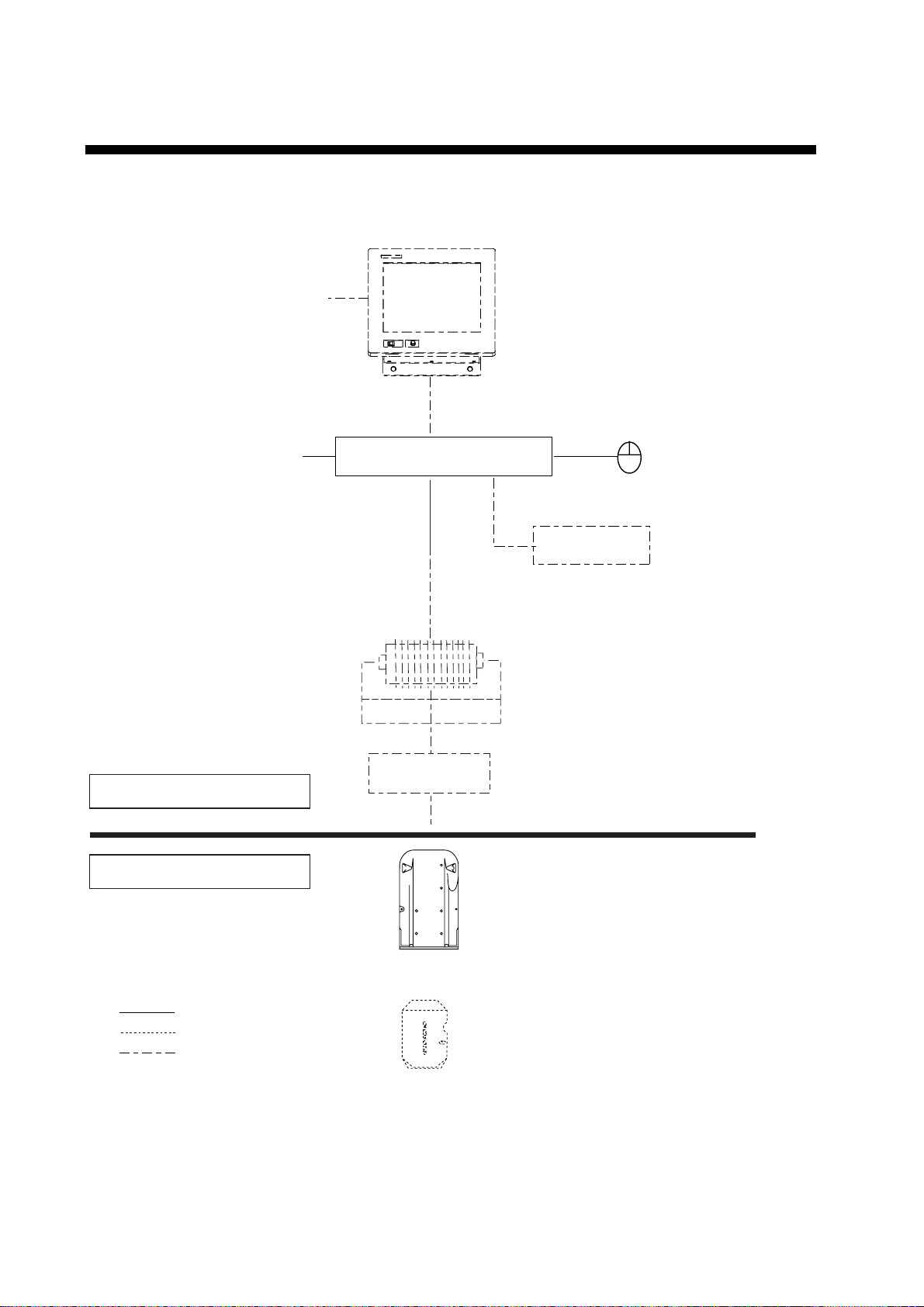
SYSTEM CONFIGURATION
PC Monitor
(User supply)
Surface Processor Unit
Winch
Power
source
100-240VAC
1
φ
, 50-60 Hz
Underwater Unit
Catch Sensor (option)
(4 max.)
: Standard supply
: Optional supply
: Local, user supply
Cable Block
UNDERWATER SECTION
SHIPBOARD SECTION
Mouse
Keyboard
System configuration

v
OPERATIONAL INFORMATION
The following may occur during operation. Follow the recommended procedure to restore
normal operation.
Cannot restore unit of temperature measurement to Celsius
Remedy
1. Choose Load Configuration from the File menu.
2. Find the file Default.cfg in the Imagenex program files and click Open.
If Fahrenheit is selected and Save Configuration is executed, the file Default.cfg will be
overwritten, which will prevent changing of unit of temperature measurement. If this occurs,
contact your dealer.
“Application error” results when the range is changed in the Settings
Dialog box after clicking the Pitch/Roll window
Remedy
1. Click “Don’t send” in the error message box at the bottom of the screen.
2. The application is quitted; click the TS331A icon to start up the application.
To change a sonar or echo sounder setting after application error occurs, first click the
corresponding window or run the corresponding diagnostic, and then change the setting.
“Application error” results when Total Length of Cod-End in the Catch
Sensor Setup dialog box is set to zero (0)
Remedy
1. Click “Don’t send” in the error message box at the bottom of the screen.
2. The application is quitted; click the TS331A icon to start up the application.
Set the Total Length of Cod-End to a value larger than 1 to prevent application error.

vi
This page intentionally left blank.
1
1. OPERATIONAL OVERVIEW
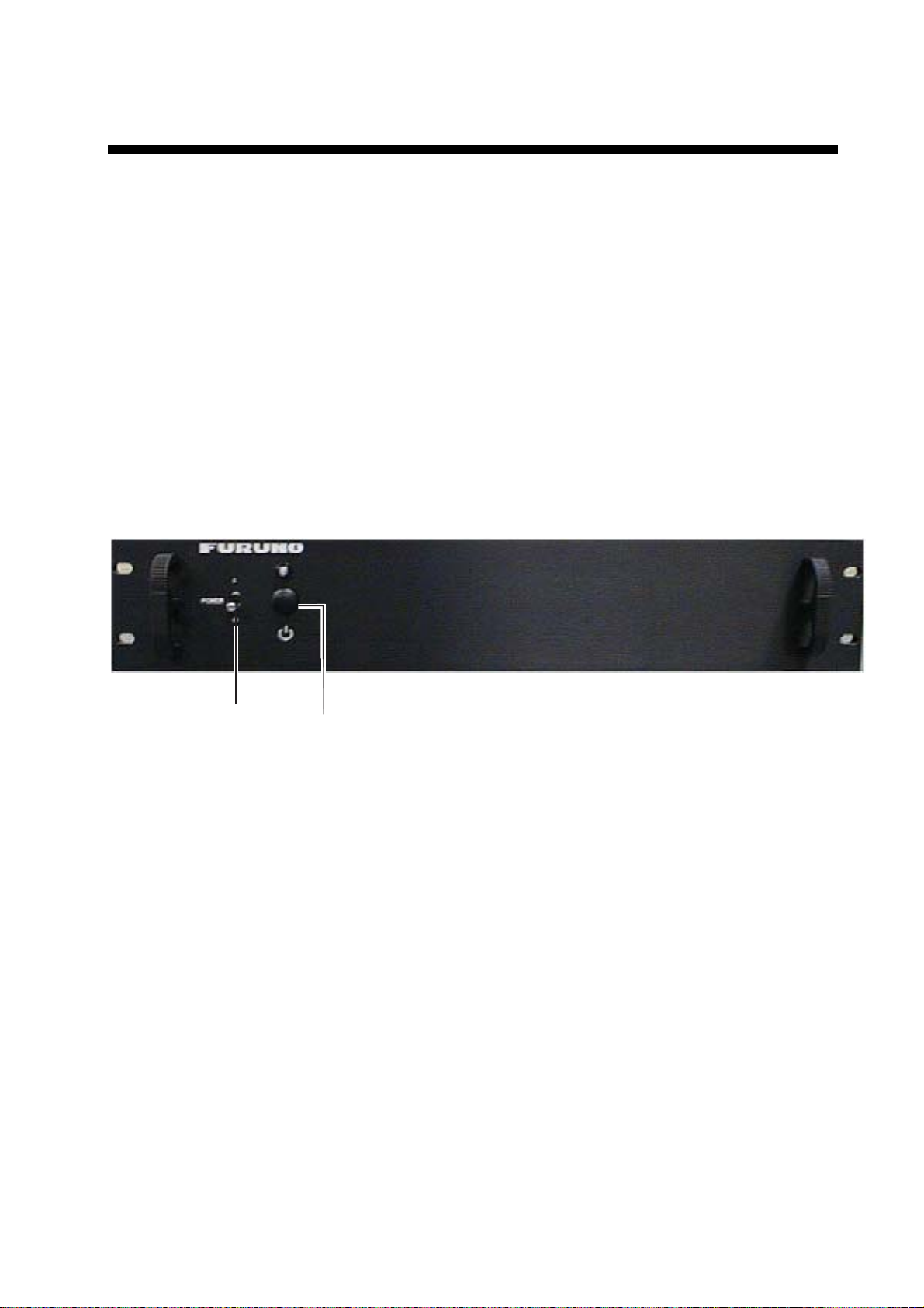
1.1 Surface Processor Unit
The Surface Processor Unit (sometimes referred to as “Processor”) has a built-in
PC mother board, Windows XP
®
* operating system, and a hard drive with at
least 2GB disk space. The system provides a control and display application
TS331A.exe (installed on the Processor), which is a very convenient tool for
users to control system parameters such as acoustic operating range, scan
speed, scan area, etc. It also displays real-tim e data such as depth/temperature,
vertical sonar images, echo sounder images, pitch and roll, and catch sensor
information on the screen in resizable windo ws .
The mouse connects at the rear of the Processor and funct ions t o control the
system, from various menus. Note that the system can also be controlled from a
keyboard (local supply).
POWER
Switch
Windows Startup
Switch
Surface processor unit
*: Windows XP is a registered trademark of Microsoft, Inc.
1. OPERATIONAL OVERVIEW
2
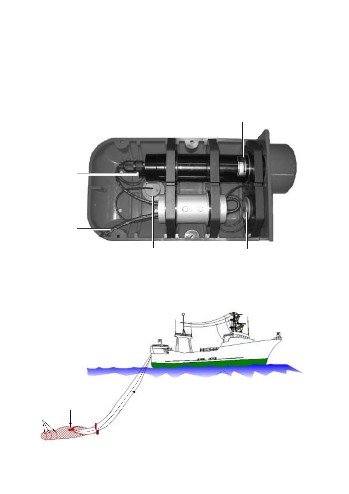
1.2 Underwater Unit
1.2.1 Components of the underwater unit
The underwater unit mainly consists of a red polyurethane case and three
transducers. The vertical sonar transducer is the cylindrical red housing which
extends from the back of the case. The (gray) echo sounder transducer is
mounted near the front of the unit. The catch sensor receiver transducer is
located at the back of the unit, to the right of the vertical sonar transducer.
Pressure
Sensor
Echo Sounder
Transducer
Third Wire
Cable
Catch Sensor
Receiver Transducer
Vertical Sonar Transducer
Underwater unit, cover removed
1.2.2 Trawl system
Underwater
Unit
Third Wire
Cable
Catch
Sensor
(option)
Trawl system
1. OPERATIONAL OVERVIEW
3
1.2.3 Mounting the underwater unit on the trawl
Usually the underwater unit is fixed either on the head rope of the trawl or on the
belly just above the ground rope.
The advantage of the former position is that the underwater unit is held
horizontal almost throughout the towing operation and consequently a good,
stable image can be expected. Its disadvantage is that it is difficult to detect the
ground rope, especially in bottom trawling since the ground rope in the bottom
trawl becomes positioned farther back than the head rope. In mid-water and
pelagic trawls, the ground rope usually becomes positioned below the head rope
and hence the ground rope is easily detected with the underwater unit on the
head rope.
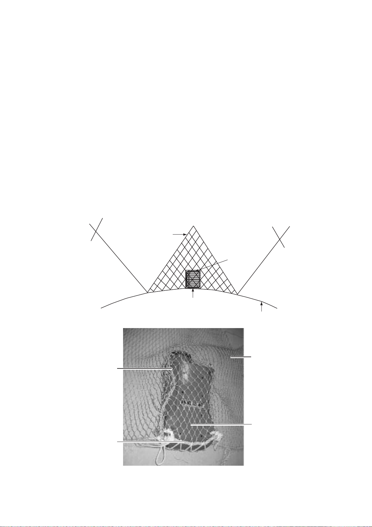
The underwater unit is typically enclosed in a “pouch” made of fine mesh netting
and attached to the head rope with ropes. The pouch is attached to a small
mesh net (smaller trawlers) with ropes to stabilize the underwater unit. (Smaller
trawlers may not require the small mesh net for stabilization.) The small mesh
net is attached to the trawl with ropes.
Underwater
Unit
Pouch for
underwater
unit
Small mesh net
Head Rope
"Pouch" made of
fine mesh netting
Underwater
Unit
Small mesh net for
stabilizing underwater
unit
Head Rope
Typical installation of underwater unit (for larger trawler)

1. OPERATIONAL OVERVIEW
4
1.3 Starting Up, Shutting Down
1.3.1 Starting up
1. Chec k the connection bet ween the underwat er unit and the winch.
2. Mount the underwater unit on the trawl, ref er r ing to paragraph 1.2.3.
3. S hoot the trawl.
4. Turn on the processor unit and t he m onitor. Adjust display brilliance referring
to the owner’s manual of t he m onitor.
5. P us h t he Windows St ar tup switch on the Processor t o s tart up Windows
®
.
The system will start up loading the Windows
®
XP* operating system and
then the TS331A progr am .
You can exit this application by clicking the “close window” button (X) at the
upper right corner of the screen or use t he m enu command Fi le->Exit.
When the power is turned on, the normal screen displ ay s hould appear. Then,
the sonar head calibrates it s elf by moving its trans ducer to the center or zero
angle and waits for the “scan comm and” from the Processor. The head then
scans based on the last-used settings of MODE, SECTOR, TRAIN and SPEED.
If the message “ No Communication” appears, check connections.
1.3.2 Shutting down
1. S ince the Processor is running a Windows
®
* operating system, before you
turn off the Processor, shut down the computer first. Click Start->Turn Off
Computer-> S hut Down. Wai t a few seconds until the system shuts dow n.
Then, t ur n off the power of the Proces sor.
2. Turn off the monitor.
3. Haul the net.
*: Windows and Windows XP are regist ered trademarks of Micr os oft, Inc.
1. OPERATIONAL OVERVIEW
5
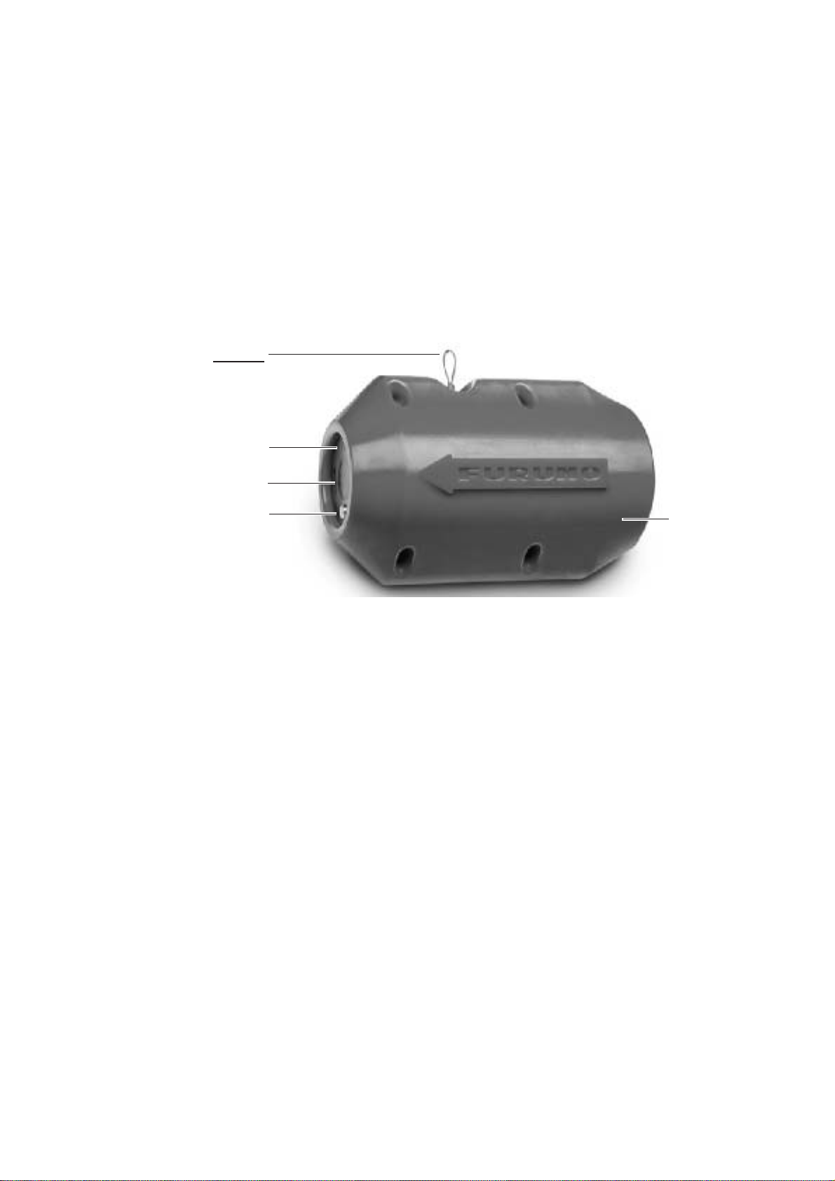
1.4 Catch Sensor CS-400 (option)
Mounted on the cod end of the trawl, the catch sensor monitors the catch of fish.
Four catch sensors may be mounted. The data from each catch sensor is
transmitted to the underwater unit via the acoustical link and sent to the
Processor. Tx frequency for each sensor is selectable with an internal jumper
block.
The catch sensor is powered by three “D” alkaline batteries. If they have
not been installed, see page 44 for ho w to install them.
Note: If the unit will not be used for a long period of time, remove the batteries.
A
coustic transducer
LED
Electrode
Lanyard
(Secured to
codend
of net.)
Polyurethan
e
Housing
Catch Sensor CS-400
1. OPERATIONAL OVERVIEW
6
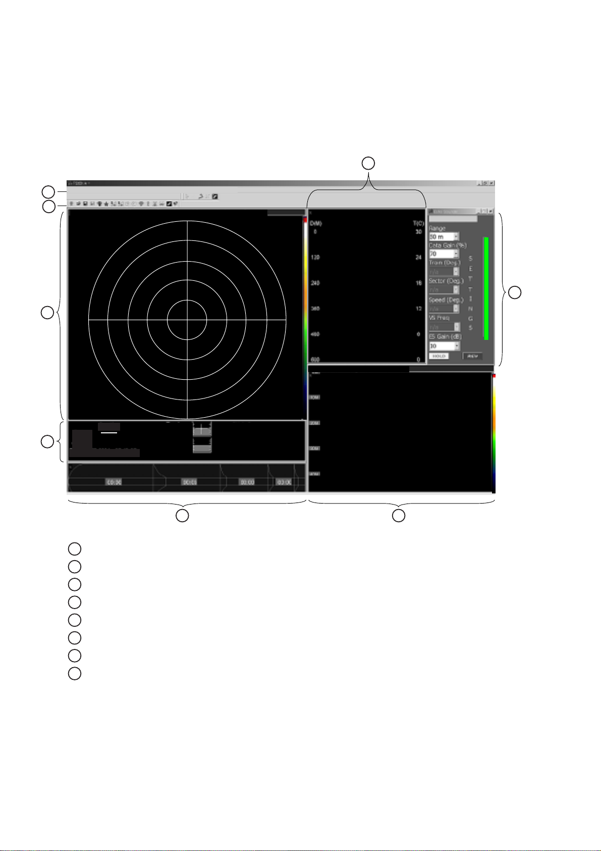
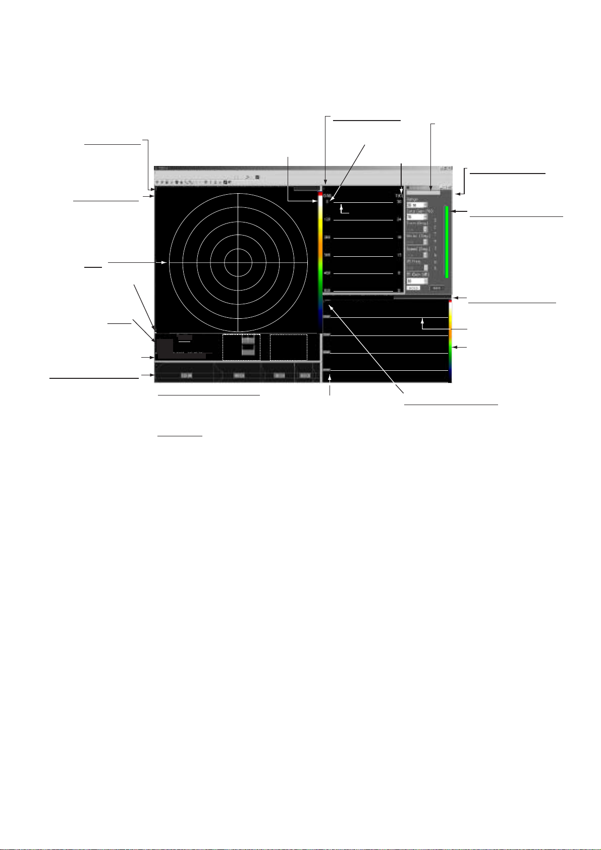
1.5 Screen Layout
The fully configured TS-331A provides five viewing windows (Vertical sonar
image, Depth/water temperature information, Echo sounder image, Catch sensor
information, and Pitch/roll information) plus a Settings dialog box*.
* The Vertical Sonar Settings dialog box is initially shown.
Menu bar
Toolbar
Vertical sonar image
Pitch/roll information
Catch sensor information
Echo sounder image
Settings dialog box*
Depth/water temperature information
DateTime 24-SEP-04 1:23:01
Ship's Course :
Ship's Speed :
Trawl Direction:
Tr. Water spd :
CE Water spd :
Trawl
Pitch: +0.0
Roll : +0.0
Cod End
Pitch:----
Roll :----
Depth
Bottom:
Trawl:
CodEnd:
3
2
3 2 1 1 6 6 1 1 2 3
3
2
1
1
6
6
1
1
2
1
2
3
4
5 6
7
8
1
2
3
4
5
6
7
8
* Items available depend on active window.
Items not available appear in gray.
*Vertical
6M/DIV
*
*
File View Color Table Grids Draw Mode Communication Diagnostics Sonar Options Help
Echo Sounder: Range: 50 M, Gain:10 dB
Sonar settings: Range: 30 M, Gain: 70%, Speed: 03', Mode: Sector, Freq: High
Screen layout
Note 1: You can drag a window’s border to resize the window to your desired size or drag
the window’s title bar to move the entire window.

1. OPERATIONAL OVERVIEW
7
Note 2: Certain devices or sensors can be manually disabled by turning them off from the
Options menu. See the figure below. The vertical sonar image cannot be disabled; it is
always displayed.
These displays can be
turned on or off.
Options menu, Echo Sounder selected
1.5.1 Menu bar
The menu bar is the horizontal strip below the title bar at the top of the screen
and it contains the titles of the TS-331A’s drop-down menus. To open a menu,
sub menu or choose an option, click it with the left mouse button. A sub menu
which has an arrow (►) means it contains an options selection window, such as
the Echo Sounder sub menu shown above.
File View Color Table Grids Draw Mode Communication Diagnostics Sonar Options Help
Menu bar
1.5.2 Toolbars
The main toolbar and the draw toolbar are displayed across the top of the
application window, below the menu bar in the normal display mode. The
toolbars provide quick mouse access to many tools used in TS-331A program.
To hide or display a toolbar, uncheck or check appropriate tool bar on the View
menu.
Main toolbar Draw toolbar
Toolbars
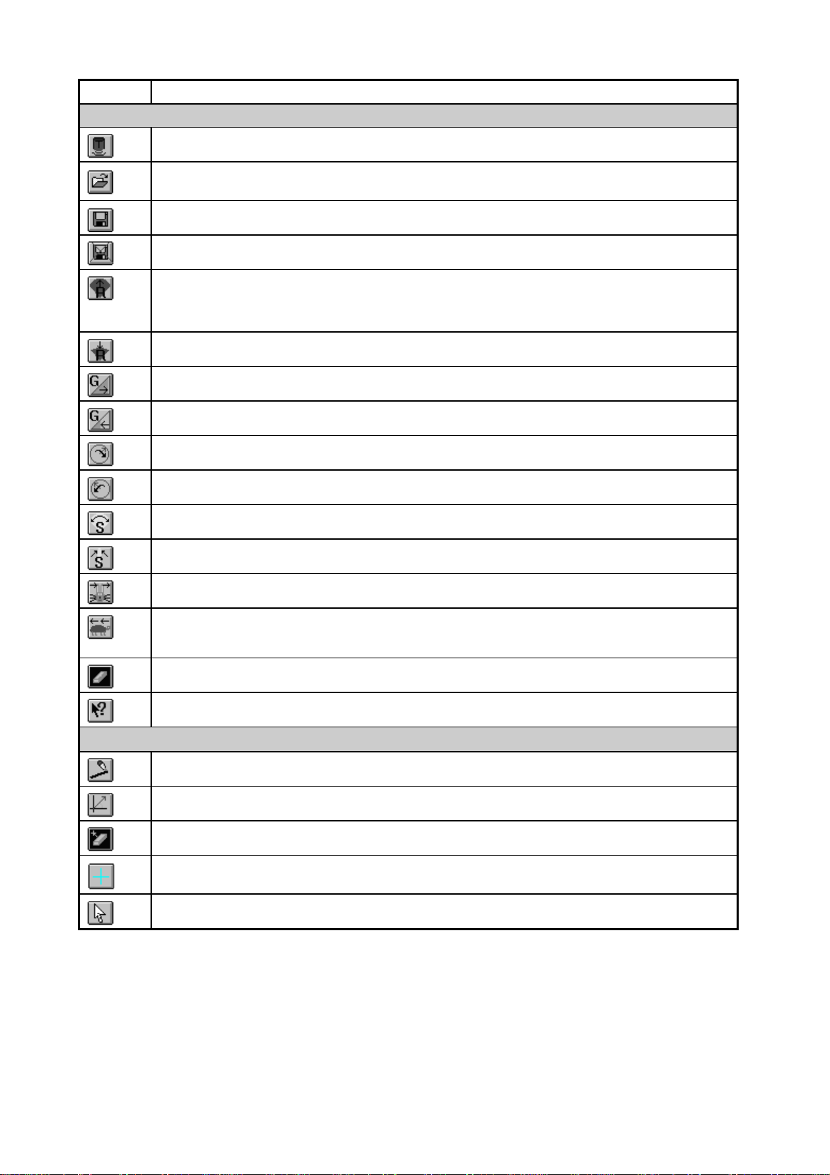
Toolbar description
1. OPERATIONAL OVERVIEW
8
Tool Function
Main Toolbar
Connects to sonar head.
Opens an existing .331 data file to play back.
Saves real-time acquired sonar data to a .331 file.
Stop saving real-time data.
Increases operating range by one level. Vertical sonar range: 10, 20, 30, 40, 50, 60,
80, 100, 150, 200, 250 (meters) or equivalent feet/fathoms. Echo sounder range: 50,
100, 150, 200, 300 (meters) or equivalent feet/fathoms.
Decreases operating range by one level.
Increases data (display) gain by 1 per cent for vertical sonar and echo sounder.
Decreases data (display) gain by 1 per cent for vertical sonar and echo sounder.
Increases train angle by 10 degrees (vertical sonar only).
Decreases train angle by 10 degrees (vertical sonar only).
Increases sector size by 10 degrees (vertical sonar only).
Decreases sector size by 10 degrees (vertical sonar only).
Increases sonar scan speed (vertical sonar only).
Decreases sonar scan speed (vertical sonar only).
Clears the screen (vertical sonar, echo sounder, and depth/temp windows).
Context sensitive help.
Draw Toolbar
Draws a line on the screen, with distance shown.
Draws a line on the screen, with range and bearing shown.
Deletes all lines and symbols drawn on the screen.
+
Draws a “+” symbol on the screen at the current mouse position.
Stops drawing objects on the screen.
1. OPERATIONAL OVERVIEW
9
1.6 Display Indications
Below are all the indications which appear on the displa y screen.
2
Ship's Course :
Ship's Speed :
Trawl Direction:
Tr. Water spd :
CE Water spd :
Trawl
Pitch: +0.0
Roll : +0.0
Cod End
Pitch:----
Roll :----
Sonar settings
Range, gain,
speed, mode,
frequency
Scale
Depth
Bottom
Trawl
Cod End
Date, Time
*1 Pitch and Roll Indicator
Analog and digital indications
of net attitude at trawl and
cod end.
*2 Nav data
Course, speed, trawl direction,
trawl water speed, cod end
water speed. Requires appropriate
sensors.
*1
*2
Grid
(Circular or
square)
6
3 2 1 1 6 6 1 1 2 3
3
2
1
1
6
1
1
2
3
6M/DIV
Scale
Color
indicator
Echo sounder settings
Range, gain
Depth
scale
Temp.
scale
Settings dialog box
Item not available with
active window is shown
in gray.
Active window indicator
Color changes according
to active window.
Med. blue : Sonar
Green : Depth/temp
Red : Echo sounder
Light blue : Catch sensor
Purple : Pitch/roll
Catch sensor indicator
Time figure is how long
since sensor has
been activated.
Color inside each
section changes with
catch sensor status.
Triggered: Red
Standby: Yellow
Sleep: Bkgd color
DateTime 24-SEP-04 1:23:01
Depth
Bottom:
Trawl:
CodEnd:
Vertical
*
Asterisk(blinking)
Green: Receiving
signal from under-
water unit
Red: No signal
*
*
Asterisk(blinking)
Green: Receiving signal
from echo sounder
Red: No signal
Asterisk(blinking)
Blinks when depth/water
temp. data is received.
FURUNO logo
appears here.
Color
indicator
Grid
Grid
File View Color Table Grids Draw Mode Communication Diagnostics Sonar Options Help
Sonar settings: Range: 30 M, Gain: 70%, Speed: 03', Mode: Sector, Freq: High
Echo Sounder: Range: 50 M, Gain:10 dB
Indications
1. OPERATIONAL OVERVIEW
10
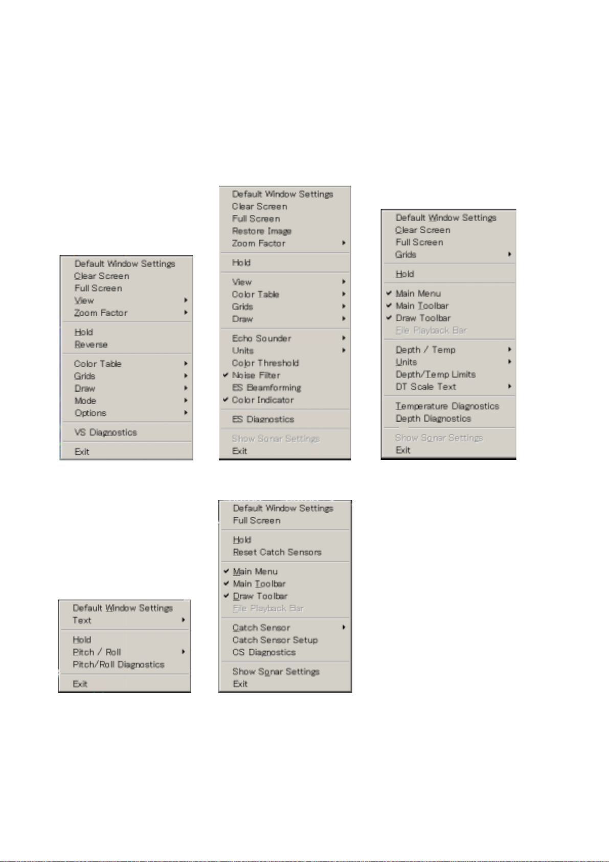
1.7 Pop-up Windows
The TS-331A provides convenient pop-up windows from which to conduct
various operations for the vertical sonar window, echo sounder window,
depth/temperature window, pitch/roll window and catch sensor window. To
activate a pop-up window, place the cursor in the window corresponding to the
pop-up menu you want to use and then click the screen with the right mouse
button.
Vertical sonar Echo sounder Depth/temperature
Pitch/roll Catch sensor
Pop-up windows
11
2. SONAR OPERATION
2.1 Choosing a Sonar Mode
The TS-331A has three sonar display modes: polar, sector and locked. Choose
desired mode from the Mode menu.
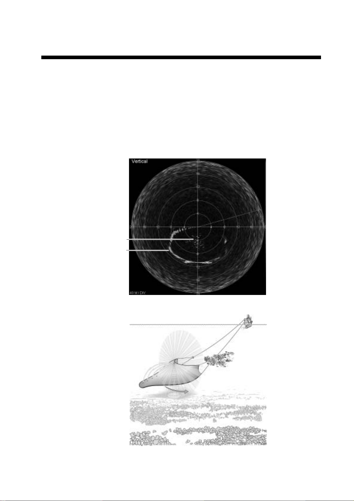
2.1.1 Polar mode
This mode is used for operating the sonar to scan a 360° area. The transducer
location is in the middle of the sonar image display with the zero heading
vertically down on the display.
Ground rope
of trawl
Fishintrawl
Polar mode display
Polar mode concept
2. SONAR OPERATION
12
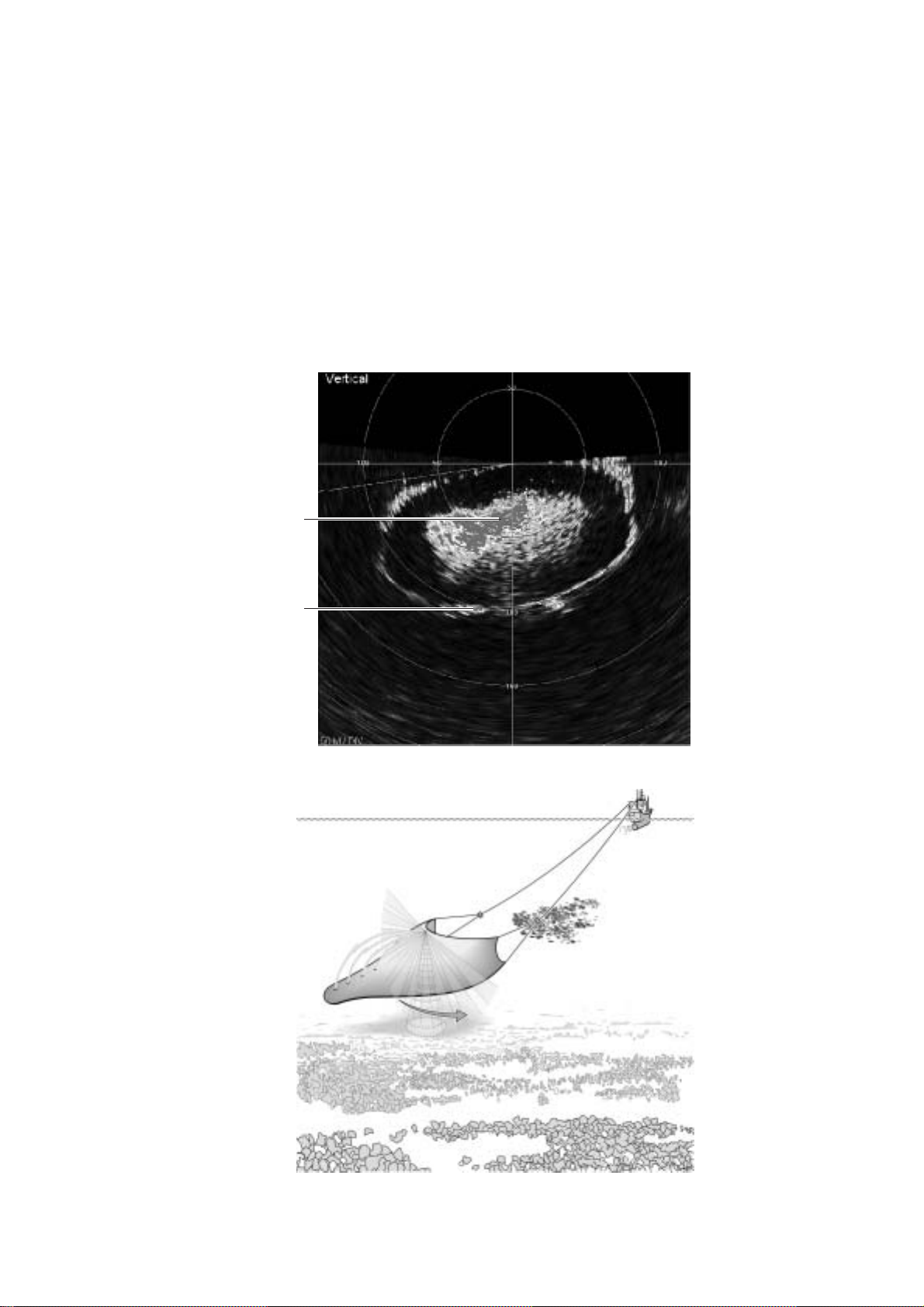
2.1.2 Sector mode
This mode is used for operating the sonar to scan in a sector area. The
transducer location is in the middle of the sonar image display with the zero
heading vertically down on the display. The user can adjust the scan sector size
by selecting the desired sector size from the Sector combo box in the Vertical
Sonar settings dialog box. Sector size can be from 0° to 360° in 10° increments.
The user can move the mid-point of the sector to any angle in 10° increments by
selecting the desired train angle from the Train combo box in the vertical sonar
settings dialog box. The user can use the Zoom Factor command in the View
menu to enlarge or shrink sonar images and the mouse can be dragged to
position the image where desired.
Ground rope
of trawl
Fishintrawl
Sector mode display
Sector mode concept
 Loading...