


 Loading...
Back
DGPS NAVIGATOR
GPS NAVIGATOR


 GP-37 /GP-32

9-52 Ashihara-cho,
Nishinomiya 662-8580, JAPAN
Telephone : |
0798-65-2111 |
|
Fax |
: |
0798-65-4200 |
All rights reserved. |
Printed in Japan |
Pub. No. OME-44200
( TATA ) GP-32/37
The paper used in this manual is elemental chlorine free.
Your Local Agent/Dealer
FIRST EDITION :MAY. 2002
E1 : MAY. 10, 2005
*00080928801*
*00080928801*
* 0 0 0 8 0 9 2 8 8 0 1 *
*OME44200E10*
*OME44200E10*
* O M E 4 4 2 0 0 E 1 0 *


 SAFETY INSTRUCTIONS
Safety Instructions for the Operator
 WARNING
Do not open the equipment.
Only qualified personnel should work inside the equipment.
Do not disassemble or modify the equipment.
Fire, electrical shock or serious injury can result.
Immediately turn off the power at the switchboard if the equipment is emitting smoke or fire.
Continued use of the equipment can cause fire or electrical shock. Contact a FURUNO agent for service.
Use the proper fuse.
Use of a wrong fuse can damage the equipment or cause fire.
NOTICE
Be sure the power supply is compatible with the equipment.
Incorrect power supply may cause the equipment to overheat.
The useable temperature range for the antenna unit is -25° C to 70° C;
-15° C to 55° C for the display unit.
Use of the equipment out of those ranges may damage the equipment.
i

Safety Instructions for the Installer
 WARNING
Do not open the cover unless totally familiar with electrical circuits and service manual.
Improper handling can result in electrical shock.
Turn off the power at the switchboard before beginning the installation.
Fire or electrical shock can result if the power is left on.
Be sure that the power supply is compatible with the voltage rating of the equipment.
Connection of an incorrect power supply can cause fire or equipment damage. The voltage rating of the equipment appears on the label above the power connector.
Use the proper fuse.
Use of a wrong fuse can damage the equipment or cause fire.
NOTICE
Observe the following compass safe distances to prevent interference to a magnetic compass:
|
Standard |
Steering |
|
|
compass |
compass |
|
|
|
|
|
Display |
0.80 m |
0.55 m |
|
unit |
|||
|
|
||
|
|
|
ii

TABLE OF CONTENTS
FOREWORD ................................... |
v |
|
SYSTEM CONFIGURATION.......... |
vi |
|
WHAT IS WAAS?.......................... |
vii |
|
EQUIPMENT LISTS ..................... |
viii |
|
1. OPERATIONAL OVERVIEW...... |
1 |
|
1.1 |
Controls ...................................... |
1 |
1.2 |
Turning On and Off Power .......... |
2 |
1.3Adjusting Brilliance and Contrast 2
1.4 |
Display Modes ............................ |
3 |
1.5 |
Menu Overview........................... |
7 |
1.6 |
Simulation Display ...................... |
8 |
2. PLOTTER DISPLAY OVERVIEW9
2.1 |
Choosing the Display Range |
....... 9 |
2.2 |
Shifting the Cursor ...................... |
9 |
2.3 |
Shifting the Display ................... |
10 |
2.4Centering Own Ship’s Position.. 10
2.5Changing Track Plotting Interval,
|
Stopping Plotting....................... |
10 |
2.6 |
Erasing Track............................. |
11 |
3. WAYPOINTS (MARKS) ............ |
13 |
|
3.1 |
Entering Waypoints................... |
13 |
3.2 |
Entering the MOB Mark ............ |
15 |
3.3 |
Displaying Waypoint Name ....... |
16 |
3.4Operations on the Waypoint List 16
3.5 Erasing Waypoints .................... |
17 |
3.6Speed for Calculating Time-to-Go,
|
|
Estimated Time of Arrival .......... |
18 |
4. |
ROUTES ................................... |
19 |
|
|
4.1 |
Creating Routes........................ |
19 |
|
4.2 |
Editing Routes .......................... |
23 |
|
4.3 |
Erasing Routes ......................... |
25 |
5. |
DESTINATION.......................... |
27 |
|
5.1 Setting Destination by Cursor ... 27
5.2Setting Destination by Waypoint 27
5.3 |
Setting Route as Destination..... |
28 |
5.4 |
Setting User Waypoint as |
|
|
Destination................................ |
28 |
5.5 |
Canceling Destination............... |
28 |
6. ALARMS................................... |
29 |
6.1Arrival Alarm, Anchor Watch
Alarm......................................... |
29 |
6.2XTE (Cross Track Error) Alarm..30
6.3 |
Speed Alarm.............................. |
31 |
6.4 |
WAAS/DGPS Alarm .................. |
31 |
6.5 |
Time Alarm ................................ |
31 |
6.6 |
Trip Alarm.................................. |
32 |
6.7 |
Odometer Alarm ........................ |
32 |
6.8 |
Buzzer Type Selection............... |
32 |
7. OTHER FUNCTIONS ............... |
33 |
|
7.1Calculating Range, Bearing,
|
TTG and ETA ............................ |
33 |
7.2 |
WAAS Setup ............................. |
34 |
7.3 |
DGPS setup .............................. |
35 |
7.4 |
Bearing Reference..................... |
37 |
7.5 |
Magnetic Variation..................... |
38 |
7.6 |
Geodetic Chart System ............. |
38 |
7.7 |
Units of Measurement ............... |
38 |
7.8 |
Position Display Format............. |
39 |
7.9Time Difference (using local time),
|
Time Format .............................. |
39 |
7.10 |
GPS Setup ................................ |
40 |
7.11 |
User Display Setup.................... |
41 |
7.12 |
Resetting Trip and Odometer |
|
|
Distances .................................. |
42 |
7.13 |
Uploading, Downloading |
|
|
Waypoint, Route Data................ |
43 |
7.14 |
Language .................................. |
46 |
8. MAINTENANCE & |
|
|
TROUBLESHOOTING ............. |
47 |
|
8.1 |
Maintenance.............................. |
47 |
8.2Displaying the Message Board ..47
8.3 |
Replacing the Fuse.................... |
48 |
8.4 |
Replacing the Battery ................ |
48 |
8.5 |
Satellite Monitor Display ............ |
49 |
8.6 |
Diagnostics................................ |
49 |
8.7 |
Clearing Data ............................ |
50 |
iii
9. INSTALLATION ........................ |
53 |
OUTLINE DRAWINGS |
|
|
9.1 |
Installation of Display Unit......... |
53 |
INTERCONNECTION DIAGRAMS |
|
9.2 |
Installation of Antenna Unit ....... |
54 |
INDEX |
Index-1 |
9.3 |
Wiring ....................................... |
55 |
||
9.4 |
Initial Settings ........................... |
56 |
Declaration of Conformity |
|
APPENDIX |
AP-1 |
|
||
|
|
|||
SPECIFICATIONS ..................... |
SP-1 |
|
|
|
iv

FOREWORD
A Word to the Owner of the GP-37, GP-32
Congratulations on your choice of the GP-37 DGPS Navigator, GP-32 GPS Navigator.
For over 50 years FURUNO Electric Company has enjoyed an enviable reputation for innovative and dependable marine electronics equipment. This dedication to excellence is furthered by our extensive global network of agents and dealers.
Your navigator is designed and constructed to meet the rigorous demands of the marine environment. However, no machine can perform its intended function unless installed, operated and maintained properly. Please carefully read and follow the recommended procedures for installation, operation, and maintenance.
We would appreciate hearing from you, the end-user, about whether we are achieving our purposes.
Thank you for considering and purchasing FURUNO equipment.
Features
The GP-37/GP-32 is a totally integrated GPS receiver and video plotter, and mainly consists of a display unit and an antenna unit. The GP-37 is additionally equipped with a DGPS beacon receiver, built in the display unit.
The high sensitivity GPS receiver tracks up to 13 satellites (12 GPS, 1 WAAS) simultaneously. An 8-state Kalman filter ensures optimum accuracy in determination of vessel position, course and speed.
The main features of the GP-37/GP-32 are
•A DGPS beacon receiver may be connected to the GP-32 to add DGPS capability.
•WAAS capability.
•Storage for 999 waypoints and 50 routes
•Alarms: Arrival/Anchor Watch, XTE (Cross-track Error), Trip, Odometer, Time, WAAS/DGPS, and Speed.
•Man overboard feature records position at time of man overboard and provides continuous updates of range and bearing when navigating to the MOB position.
•Bright 95 x 60 mm LCD with adjustable contrast and brilliance.
•Autopilot (option) may be connected, and steering data output to the autopilot.
•Unique Highway display provides a graphic presentation of ship’s progress toward a waypoint.
•User displays definable by operator.
•Waypoint and route data can be uploaded from a PC and downloaded to a PC.
v
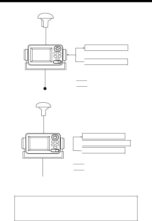
SYSTEM CONFIGURATION
Note: This equipment is intended for use on marine vessels. Do not use it in other applications.
ANTENNA UNIT
GPA-019
PROCESSOR UNIT*
FURUNO GPS NAVIGATOR |
NAVIGATOR |
 PERSONAL COMPUTER
* = With DGPS beacon receiver
: Standard Supply
: Option
12/24 VDC
GP-37 system configuration
ANTENNA UNIT
GPA-017
PROCESSOR UNIT
FURUNO GPS NAVIGATOR |
NAVIGATOR |
|

 DGPS BEACON RECEIVER
 PERSONAL COMPUTER
: Standard Supply
: Option
 12/24 VDC
GP-32 system configuration
This GPS receiver complies with Canadian standard RSS-210 (Low Power License-Exempt Radio communication Devices).
Operation is subject to the following two conditions:
(1)this device may not cause interference, and
(2)this device must accept any interference, including interference that may cause undesired operation of the device.
vi

WHAT IS WAAS?
WAAS, available in North America, is a provider in the worldwide SBAS (Satellite Based Augmentation System) navigation system. An SBAS provider furnishes GPS signal corrections to SBAS users, for even better position accuracy, typically better than three meters. Two more SBAS providers are also currently under development, MSAS (Multi-Functional Satellite Augmentation System) for Japan and EGNOS (Euro Geostationary Navigation Overlay Service) for Europe. All providers will be compatible with one another, thus providing “seamless” position fixes to SBAS users.
At the time of this software release, WAAS is still in the developmental phase. During this developmental phase, which may last several years, there is no guarantee of the accuracy, integrity, continuity, or availability of the WAAS signal. Therefore, FURUNO will accept no responsibility for the use of the signal for other than the above stated purpose. It is the user’s responsibility to exercise common prudence and navigational judgment when using the WAAS signal.
150° W |
120° W |
90° W |
60° W |
30° W |
0 |
30° E |
60° E |
90° E |
120° E |
150° E |
|
60° N |
|
|
|
|
|
|
|
|
|
|
60° N |
40° N |
|
|
|
|
|
|
EGNOS |
|
MSAS |
40° N |
|
|
|
|
|
|
|
|
|
|
|
|
|
20° N |
|
|
|
|
|
|
|
|
|
|
20° N |
0 |
|
|
|
122 |
120 |
|
131 |
|
|
134 |
0 |
|
WAAS |
|
|
|
|
|
|
|
|
|
|
20° S |
|
|
|
|
|
|
|
|
|
|
20° S |
40° S |
|
|
|
|
|
|
|
|
|
|
40° S |
60° S |
|
|
|
|
|
|
|
|
|
|
60° S |
150° W |
120° W |
90° W |
60° W |
30° W |
0 |
30° E |
60° E |
90° E |
120° E |
150° E |
|
Satellite, Region |
Position |
120, AOR-E |
15.5° W |
122, AOR-W |
54° W |
131, IOR |
64.5° E |
134, POR |
178° E |
Expected operations capability WAAS: 2003
EGNOS: 2004
MSAS: 2005
Note: This manual uses “WAAS” when referring to any SBAS provider.
vii

EQUIPMENT LISTS
Standard supply
Name |
Type |
Qty |
Remarks |
Display |
GP-37 |
1 |
With hanger, knob |
Unit |
GP-32 |
|
|
|
|
||
Antenna |
GPA-019 |
1 |
For GP-37, w/10 m cable |
Unit |
GPA-017 |
1 |
For GP-32, w/10 m cable |
|
|
|
|
Installation |
CP20-02310 |
1 set |
• Power/data cable (1 pc.) |
Materials |
|
|
(Type: MJ-A7SPF0009-020, Code No.: 000-145-612) |
|
|
|
• Tapping screw (4 pcs.) |
|
|
|
(Type: 5X20, Code No.: 000-802-081) |
Spare Parts |
SP20-01001 |
1 set |
Fuse (2 pcs.) |
|
|
|
(Type: FGMB1A, Code No.: 000-114-805) |
Template |
C42-00201 |
1 |
Code No. 000-809-299, flush mounting template |
Hard Cover |
FP14-02801 |
1 |
Code No. 004-366-960 |
|
|
|
|
Optional equipment
Name |
Type |
Code No. |
Qty |
Remarks |
Right Angle |
NO.13-QA330 |
000-803-239 |
1 |
For mounting the antenna |
Antenna Base |
|
|
|
unit, choose one |
L-type Antenna |
NO.13-QA310 |
000-803-240 |
1 |
|
Base |
|
|
|
|
Handrail |
NO.13-RC5160 |
000-806-114 |
1 |
|
Antenna Base |
|
|
|
|
Mast Mounting |
CP20-01111 |
004-365-780 |
1 set |
|
Kit |
|
|
|
|
Cable Assy. |
MJ-A7SPF0009-020 |
000-145-612 |
1 |
|
|
|
|
|
|
Flush Mounting |
OP20-29 |
000-041-405 |
1 set |
For flush mounting the |
Kit F |
|
|
|
display unit, choose one |
Flush Mounting |
OP20-17 |
000-040-720 |
1 set |
|
Kit S |
|
|
|
|
viii
1. OPERATIONAL OVERVIEW
1.1 Controls
Press once: Zoom, centering, or escapes from current operation, depending on display in use.
Press twice: Opens menu.
Chooses display mode.
MENU ENT
DISP GOTO
MARK
MOB
DIM
PWR
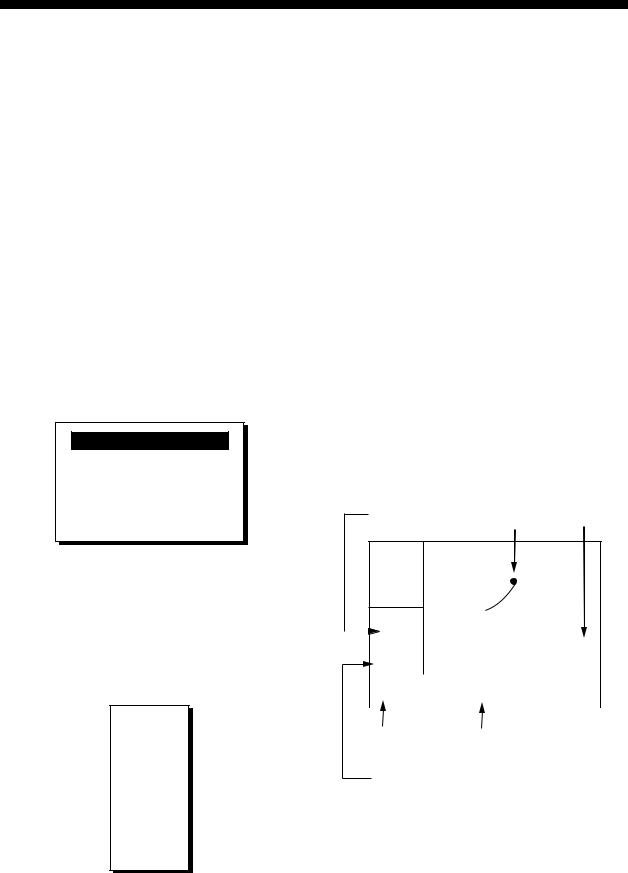
Control panel
How to attach and remove the hard cover
To attach the hard cover, set it to the display unit at an angle. To remove the hard cover, do as follows:
Press at arrows and pull toward you to remove.
Cursor Pad
•Shifts cursor (cursor displayed) and display (cursor off).
•Selects items on menus.
•Enters alphanumeric data.
Registers items on menus.
Sets/cancels destination.
Momentary press: Inscribes mark.
Long press: Inscribes MOB mark.
Momentary press: Turns
power on. With the power on, press to adjust dimmer and contrast.
Long press: Turns power off.
1
1. OPERATIONAL OVERVIEW
1.2 Turning On and Off Power
Turning on the power
Press the [DIM/PWR] key. The unit beeps and then starts up with the last-used display mode.
Note: The example screens shown in this manual may not match the screens you see on your display. The screen you see depends on your system configuration and equipment settings.
Your equipment takes about 90 seconds to find its position when turned on for the very first time. Thereafter it typically takes about 12 seconds.
The equipment shows receiver status indication at the top left-hand corner in most display modes. The table below shows these indications and their meanings.
Receiver status indications
Indication |
|
Meaning |
2D |
2D |
GPS position fix |
3D |
3D |
GPS position fix |
D2D |
2D |
DGPS position fix |
D3D |
3D |
DGPS position fix |
W2D |
2D |
WAAS position fix |
W3D |
3D |
WAAS position fix |
DOP* |
2D: HDOP larger than 4 |
|
|
3D: PDOP larger than 6 |
|
SIM |
Simulation mode |
|
* = DOP (Dilution of Precision) is the index of position accuracy and is the distribution pattern of satellites used in position fixing. Generally, the smaller the figure the better the position accuracy.
Turning off the power
Press and hold down the [DIM/PWR] key until the screen goes blank (about three seconds). The time remaining until the power is turned off is counted down on the display.
1.3Adjusting Brilliance and Contrast
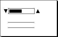
1.Press the [DIM/PWR] key momentarily. The display shown below appears.
B R I L L |
( 1 ~ 8 ) |
4
C O N T R A S T ( 0 ~ 6 3 )


 4 1
4 1
E X I T : [ E N T ]
Brilliance and contrast adjustment window
2.To adjust the brilliance, press ▲ or ▼. Current setting is shown to the right of ▲. Maximum setting is 8.
3.To adjust the contrast, press ◄ or ►. Current setting is shown to the right of ►. Maximum setting is 63.
4.Press the [ENT] key to finish.
Note: If the last-used contrast setting is 36 or higher, the equipment starts up with that setting. If the setting is 35 or lower, the equipment starts up with setting 36.
2
1. OPERATIONAL OVERVIEW
1.4 Display Modes
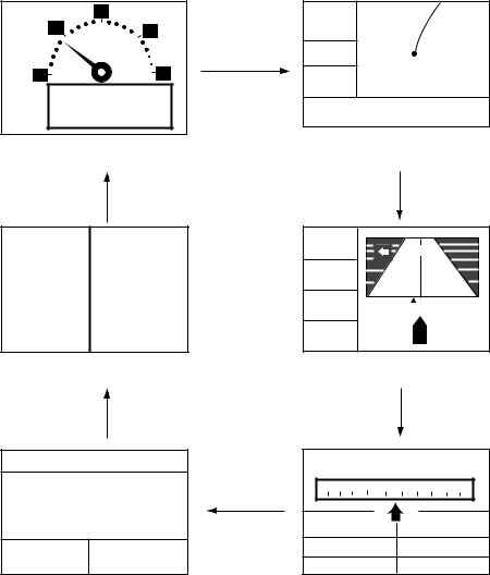
Your unit has five display modes: Plotter Display, Highway Display, Steering Display, Nav Data Display and User Display (digital data and speedometer). Press the [DISP] key to choose a display mode. Each time the key is pressed, the display mode changes in the sequence shown below.
|
20 |
D2D |
|
10 |
30 |
[ 5 mn ] |
|
|
[DISP] key |
COG: |
X |
|
|
357° |
|
0 |
40 |
SOG: |
|
|
|
10.0 k |
|
|
9.960KT |
t |
|
SOG 0 |
34° 44.000N 135° 21.000E |
||
[User Display: Speedometer] |
[Plotter Display] |
||
|
(Display format |
|
|
[DISP] key |
depends on user setting.) |
|
[DISP] key |
|
|
||
POWER(V) SOG(KT)
12.1 |
9.9 |
TRIP(NM) |
COG(° ) |
9.99 |
5.6 |
[User Display: Digital Data]
(Display format
depends on user setting.)
[DISP] key
BRG 242°
COG 357°
RNG17.5 n
m
SOG10.0k
t
004
[+] |
0.05 |
|
0.05 |
|
|
||||||||||||||
0.5 |
|
|
|
|
|
|
|
|
|
|
|
|
|
|
||||
|
|
|
|
|
|
|
|
|
|
|
|
|
|
|
|
|
|
|
XTE 0.05mn
[Highway Display]
[DISP] key
D2D 02-FEB-02 15:37:40 |
D2D MAG |
CURSOR |
15:37 |
|||
|
|
|
|
|
||
34° 44. |
000'N |
300 |
330 |
N |
30 60 |
E |
|
|
|
|
|
||
135° 21. |
000'E |
SOG: |
10.0 kt |
COG: |
357° |
|
|
[DISP] key |
|||||
SOG: 10.0 kt |
COG: 357° |
RNG: |
17.5 nm |
BRG: |
242° |
|
TTG: |
1H30M |
ETA: 12:30 |
||||
[Nav Data Display] |
[Steering Display] |
|||||
Display modes (default user displays)
Note 1: The unit measures distances up to 9999 nm. Any distance greater than 9999 nm is shown as “*999”.
Note 2: Position data can be shown in latitude and longitude or TDs (Loran C or Decca).
3
1. OPERATIONAL OVERVIEW
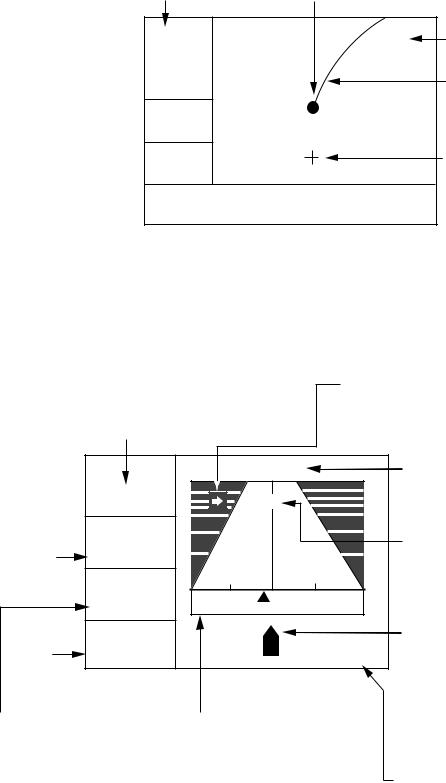
Plotter display
The plotter display traces own ship’s track, and shows position, bearing to cursor, range to cursor, horizontal display range setting and receiver status.
Receiver status
(See table on page 2.) Own ship mark (blinking)
D2D |
X |
Horizontal display  [ 40 mn ] range setting
BRG: +
Bearing  180°
180°
to cursor*
RNG: +
Range  12.0 mn to cursor*
34° 44.000N 135° 21.000E 
*= COG and SOG replace bearing to cursor and range to cursor when the cursor is not displayed.
Waypoint mark (Shape selectable)
Boat's track
Cursor
(Displayed six seconds.)
Cursor position
(Own ship position when cursor is not displayed.)
Plotter display
Highway display
The highway display provides a 3-D view of own ship’s progress toward destination (waypoint). Nav data is also shown.
Bearing from own ship to destination waypoint
Direction to steer (to return to course) Appears to right or left of centerline depending on direction to steer;
 : Steer right,
  : Steer left.
|
BRG 11° |
|
|
CURSOR |
|
|
||
|
|
|
|
[+] |
|
|
|
|
|
|
|
|
|
|
|
|
|
Course |
COG 11° |
|
|
|
|
|
|
|
over |
|
|
0..35 |
|
|
|
0.5 |
|
ground |
|
|
|
|
NI |
|
|
|
|
n |
I |
I |
I |
I |
I |
I |
|
|
RNG 9.0m |
|
|
|
|
|
|
|
Speed |
k |
|
|
|
|
|
0.05 mn |
|
SOG12.5t |
|
XTE |
|
|
|
|||
over |
|
|
|
|
|
|
|
|
ground |
|
|
|
|
|
|
|
|
Range from own ship to destination waypoint
Analog XTE (Cross-track error) scale Arrow shifts with boat's XTE. When the arrow is aligned with the centerline
the boat is on course. The arrow blinks if boat's XTE is greater than XTE scale range. "N" (North) is displayed instead of the arrow when no destination is set.
Highway display
Destination waypoint name "CURSOR" (cursor-selected destination) or waypoint name
Destination waypoint Moves forward as boat nears destination.
∆ C (Delta Course) The boat mark displays course as follows:
When no waypoint is set; The mode is North-up and
the arrow shows boat's course. When a waypoint is set;
The arrow shows boat's course towards destination.
Digital XTE indication (in nautical miles)
4
1. OPERATIONAL OVERVIEW
Steering display
The steering display provides steering information such as ship’s speed, course, range, bearing, ETA and TTG.
|
|
|
|
|
|
|
Receiver status |
|
|
|
|
|
|
|
|
|
|
|
|
|
|
||||||
|
|
|
|
|
|
|
|
|
|
Bearing reference (MAG or TRUE) |
|
|
|
||||||||||||||
|
|
|
|
|
|
|
|
|
|
|
|
|
|
|
|
|
|
Destination (CURSOR or waypoint name) |
|||||||||
|
|
|
|
|
|
|
|
|
|
|
|
|
|
|
|
|
|
|
|
|
|
|
|
|
|
|
Time |
|
|
|
|
|
|
|
D2D |
MAG |
CURSOR |
|
04:32 |
|
Bearing from own ship |
||||||||||||||
|
|
|
|
|
|
|
|
|
|
|
|
|
|
|
|
|
|
|
▼ |
|
|
|
|
|
|
to destination |
|
|
|
|
|
|
|
|
|
|
|
|
|
|
|
|
|
|
|
|
|
|
|
|
|
|
|
|
|
|
|
|
|
|
|
|
|
|
W 300 |
330 |
N |
30 |
60 |
E |
|
|
|
Bearing scale |
|||||||||
|
|
|
|
|
|
|
|
|
I |
I I I |
I I |
I |
|
I I I |
I I |
I |
|
|
|
|
|||||||
|
|
|
|
|
|
|
|
|
|
|
|
|
|
|
|||||||||||||
Speed over ground |
|
|
|
|
|
|
|
|
|
|
|
|
|
|
|
|
|
|
|
|
|
|
|
|
Own ship mark |
||
|
|
|
|
|
|
|
|
|
|
|
|
|
|
|
|
|
|
|
|
|
|
|
|
||||
|
|
|
|
|
|
|
|
|
|
|
|
|
|
|
|
|
|
|
|
|
|
|
|
||||
|
|
|
|
|
|
|
|
|
|
|
|
|
|
|
|
|
|
|
|
|
|
|
|
|
|
||
|
|
|
|
|
|
|
|
|
|
|
|
|
|
|
|
|
|
|
|
|
|
|
|
|
|
||
|
|
|
|
|
|
|
|
|
|
|
|
|
|
|
|
|
|
|
|
|
|
|
|
||||
|
|
|
|
|
|
|
|
|
|
|
|
|
|
|
|
|
|
|
|
|
|
|
|||||
|
SOG: |
12.5 kt |
|
|
|
COG: 354° |
|
Course over ground |
|||||||||||||||||||
|
|
|
|
|
|
|
|
|
|
|
|||||||||||||||||
Range from own ship |
|
|
|
|
RNG: |
0.16 nm |
|
|
|
|
BRG: |
60° |
|
|
|
|
|
|
Bearing |
||||||||
|
|
|
|
|
|
|
|
|
|
|
|
|
|
||||||||||||||
|
|
|
|
|
|
|
|
|
|
|
|
||||||||||||||||
to destination |
|
|
|
|
|
|
|
|
|
|
|
|
|
|
|
|
|
|
|
|
Estimated Time of |
||||||
|
TTG: |
1H 30M |
|
|
|
|
|
ETA: |
12:30 |
|
|
|
|
|
|
||||||||||||
Time-To-Go |
|
|
|
|
|
|
|
|
|
|
|
|
|
|
|
|
|
||||||||||
|
|
|
|
|
|
|
|
|
|
|
|
|
|
|
|
||||||||||||
|
|
|
|
|
|
|
|
|
|
|
|
|
|
|
|
|
|
|
|
|
|
|
Arrival at destination |
||||
|
|
|
|
|
|
|
|
|
|
|
|
|
|
|
|
|
|
|
|
|
|
||||||
to destination |
|
|
|
|
|
|
|
|
|
|
|
|
|
|
|
|
|
|
|
(*9:*9 shown when |
|||||||
(*9H*9M is displayed |
|
|
|
|
|
|
|
|
|
|
|
|
|
|
|
|
|
|
|
ETA is over 99h59min.) |
|||||||
when TTG is over 99 h59min.) |
|
|
|
|
|
|
|
|
|
|
|
|
|
|
|
|
|||||||||||
Steering display
Nav data display
The nav data display shows receiver status, position in latitude and longitude (or TDs), course over ground, speed over ground, date and time.
Receiver status
|
D2D |
10-JAN-02 16 :44 :15 |
||||
|
34 |
° 44 |
.000' |
|||
|
|
|
° |
|
|
N |
|
135 |
21 |
.000' |
|||
|
|
|
|
|
|
E |
Speed over ground |
SOG: |
12.5 |
kt COG: |
7° |
||
Date and time
Position in latitude and longitude
Course over ground
Nav data display
5
1. OPERATIONAL OVERVIEW
User displays
Two user displays are available, digital and speedometer.
Digital display
The digital display shows digital navigation data. The user may choose what data to display in one to four cells. The choices of data are time, speed over ground, cross-track error, odometer distance, position, course over ground, time-to-go to destination, trip distance, power source voltage, range and bearing to waypoint, and estimated time of arrival at destination.
POWER(V) SOG(KT)
12.19.9
TRIP(NM) COG(° )
9.995.6
Digital display (default display)
Speedometer display
The speedometer display provides both digital and analog displays of speed over ground.
|
20 |
10 |
30 |
0 |
40 |
SOG 0 |
9.360KT |
Speedometer display
6
1.5 Menu Overview
Most operations of your unit are carried out through the menu. Below is a quick introduction to how to choose a menu and change menu settings. If you get lost in operation, press the [MENU] key to return to the MAIN MENU. For your reference, a complete menu tree appears in the Appendix.
1.Press the [MENU] key once or twice to display the menu.
One press: Steering display, nav data display and user display.
Two presses: Plotter display, highway display.
MAIN MENU
WAYPOINTS |
|
MESSAGES |
ROUTES |
|
SATELLITE |
PLOTTER |
|
USER DISP |
ALARMS |
|
GPS SETUP |
ERASE |
|
SYS SETUP |
WAAS/DGPS |
|
I/O SETUP |
CALCULATE |
|
TD SETUP |
|
|
|
Main menu
2.Operate the cursor pad to choose a menu and then press the [ENT] key. For example, choose PLOTTER and then press the [ENT] key.
PLOTTER SETUP
TRACK REC |
: |
DISTANCE |
INTERVAL |
: 0.10 nm |
|
BRG. REF. |
: MAG |
|
MAG. VAR. |
: AUTO E16 |
|
WPT NAME |
: DSP GOTO |
|
TTG/ETA SPD |
|
: AUTO |
TRACK MEMORY USED 1%
PLOTTER SETUP menu
3.Use ▲ or ▼ to choose menu item. For example, choose TRACK REC.
4.Press the [ENT] key. A window shows the options for the item selected. (The illustration at the top of the next shows the options available for TRACK REC.)
1. OPERATIONAL OVERVIEW
OFF
DISTANCE
AUTO
Track recording options
5.Press ▲ or ▼ to choose option desired.
6.Press the [ENT] key to register your selection.
7.Press the [MENU] key twice to close the menu.
How to enter alphanumeric data
In some instances it is necessary to enter alphanumeric data. The example below shows how to enter a time difference of -6:30, to use local time instead of UTC time.
1.Press the [MENU] key once or twice to display the menu.
2.Choose SYS SETUP and then press the [ENT] key.
|
|
|
SYSTEM SETUP |
|
|
|
LANGUAGE : |
|
|
|
|||
ENGLISH |
|
|
||||
DATUM |
: WGS84 |
|
|
|||
UNITS |
: nm, kt |
|
|
|||
TIME DIFF |
: +00 : 00 |
|
|
|||
TIME DISP |
: 24HOUR |
|
|
|||
TEST? |
|
|
|
|
||
SIMULATOR?
EXCHANGE BATTERY?
SYSTEM SETUP menu
3.Choose TIME DIFF.
4.Press the [ENT] key. A cursor circumscribes “+”. This cursor appears whenever selected data can be changed with the cursor pad.
SYSTEM SETUP
LANGUAGE : ENGLISH
DATUM |
: WGS84 |
UNITS |
: nm, kt |
TIME DIFF |
: +00 : 00 |
TIME DISP |
: 24HOUR |
TEST? |
|
SIMULATOR?
EXCHANGE BATTERY?
SYSTEM SETUP menu,
TIME DIFF selected
7
1. OPERATIONAL OVERVIEW
5.Press ▲ to display “-“.
6.Press ► to send the cursor to the next digit.
7.Press ▲ or ▼ to display “0.”
8.Press ► to send the cursor to the next digit.
9.Press ▲ or ▼ to display “6.”
10.Press ► to send the cursor to the next digit.
11.Press ▲ or ▼ to display “3.”
12.Press ► to send the cursor to the last digit.
13.Press ▲ or ▼ to display “0.”
14.Press the [ENT] key.
15.Press the [MENU] key twice to finish.
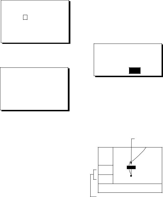
1.6 Simulation Display
The simulation display provides simulated operation of this unit. You may set the speed manually and course manually or automatically. All controls are operative - you may enter marks, set destination, etc.
1.Press the [MENU] key once or twice to display the menu.
2.Choose SYS SETUP and then press the [ENT] key.
3.Choose “SIMULATOR?” and then press the [ENT] key. (Note that position shown depends on language selected on the SYS SETUP menu. After changing the language, the memory is cleared.)
|
|
|
SIMULATOR |
|
||
MODE |
: |
|
|
|
||
OFF |
|
|||||
SPEED |
: |
|
20 kt |
|
|
|
COURSE |
: |
|
AUTO |
|
||
LAT |
: |
|
38° 00'N |
|
||
LON |
: |
|
123° 00'W |
|
||
SIMULATOR menu
4.The cursor is selecting MODE. Press the [ENT] key. A window shows the choices ON and OFF.
5.Choose ON and then press the [ENT] key.
6.Press the [ENT] key, use the cursor pad to enter speed to use for the simulation, and then press the [ENT] key.
7.Press the [ENT] key.
8.Choose course (AUTO or MAN) and then press the [ENT] key. For manual entry of course, press the [ENT] key, enter course with the cursor pad, and then press the [ENT] key. The AUTO course tracks a circular course.
Note: Course must be AUTO to set simulation destination.
9.Press the [ENT] key, enter latitude with the cursor pad, and then press the [ENT] key.
10.Press the [ENT] key, enter longitude, and then press the [ENT] key.
11.Press the [MENU] key twice.
12.Choose the PLOTTER display with the [DISP] key. SIM appears at the upper left-hand corner when the simulator display is active.
Simulation mode active
SIM |
|
|
|
|
|
|
[ 40 mn ] |
|
|
|
|
|
|
|
|
|
|
|
|
Course traced |
COG: |
|
|
|
|||
|
|
|
|
|
||
|
|
|
|
|
||
82° |
|
|
|
|
|
in AUTO course |
|
|
|
|
|
|
|
SOG: |
|
|
|
|
|
|
9.0 kt |
|
|
|
|
|
|
34° 44.000N |
135° 21.000E |
|||||
|
|
|
|
|
|
|
Simulator display, auto course selected
13.To turn off the simulator display, choose OFF at step 5 in this procedure, press the [ENT] key and then press the [MENU] key twice to finish.
Note: If the power is turned off while the simulator display is in use, the indication SIMULATION MODE appears at the top of the screen at the next power up, in addition to the indication SIM. SIMULATION MODE disappears when any key is pressed, however the simulation mode continues.
8
2. PLOTTER DISPLAY OVERVIEW
2.1Choosing the Display Range
You may choose the display range on the plotter and highway displays. The horizontal range in the plotter display is available among 0.02 (40 yd), 0.05 (101 yd), 0.1 (202 yd), 0.2 (405 yd), 0.5, 1, 2, 5, 10, 20, 40, 80, 160 and 320 nautical miles. (Nautical mile is the default unit of display range. Display range may also be shown in kilometers or miles. Ranges shorter than the 0.5 nm are also shown in yards or meters on the plotter display.) The horizontal range in the highway display is available among 0.2, 0.4, 0.8, 1, 2, 4, 8 and 16 nautical miles.
1.Press the [MENU] key. The zoom, ship centering window appears.
ZOOM IN/OUT?
SHIP TO CENTER?
Quit?
PRESS [MENU] TO SEE
THE MAIN MENU.
Zoom, ship centering window
Note: “SHIP TO CENTER?” does not appear when the highway display mode is active.
2.ZOOM IN/OUT is selected. Press the [ENT] key to show the zoom window.
ZOOM
▲O U T
2 0 mn
▼I N
E X I T : [ E N T ]
Zoom window
3.Use ▲ (increase) or ▼ (decrease) to choose range desired.
4.Press the [ENT] key to close the zoom, ship centering window.
2.2 Shifting the Cursor
Use the cursor pad to shift the cursor. The cursor moves in the direction of the arrow or diagonal pressed on the cursor pad.
Cursor state and data
Cursor state determines what data is shown on the display.
Cursor turned on
Cursor position is displayed in latitude and longitude or TDs (depending on menu setting) at the bottom of the plotter display when the cursor is on. The range and bearing from own ship to the cursor appear at the left-hand side of the display.
Bearing from own Own ship Cursor ship to cursor
D2D
[ .02mn ]
40y d
|
|
BRG: + |
|
|
|
|
|
|
|
||
|
131° |
|
|
|
|
|
|
|
|
||
|
|
|
|
|
|
|
|
|
|||
|
|
|
|
|
|
|
|
|
|
|
|
|
|
RNG: + |
|
|
|
|
|
|
|
||
|
|
|
|
|
|
|
|
|
|||
|
|
|
|
|
|
|
|
||||
|
|
0.03 mn |
|
|
|
|
|
|
|
||
|
|
+ 34° 44.000N |
135° 21.000E |
||||||||
|
|
|
|
|
|
|
|
|
|
|
|
|
|
|
|
||||||||
|
|
|
|
|
|||||||
Cursor mark |
Cursor position in |
||||||||||
|
|
|
|
|
latitude and longitude |
||||||
Range from own ship to cursor
Plotter display, cursor turned on
9
2. PLOTTER DISPLAY OVERVIEW
Cursor turned off
The cursor is erased when there is no cursor pad operation for about six seconds. Ship’s position, speed and course appear when the cursor is off.
|
|
|
Own ship's position |
||
|
|
|
(Blinking) |
||
|
|||||
Course over ground |
|
||||
|
|
|
|
|
|
D2D |
|
|
|
|
|
[ 40 mn ] |
|
|
|
|
|
|
|
|
|
|
|
|
|
|
|
|
|
COG: |
|
|
|
|
|
7° |
|
|
|
|
|
SOG: |
|
|
|
|
|
9.0 kt |
|
|
|
|
|
34° 44.111N |
135° 20.555E |
|
|||
|
|
|
|
|
|
Speed |
|
|
|
|
|
|
|
|
|
||
|
|
|
|
||
over |
Own ship's position in |
||||
ground |
latitude and longitude |
||||
Plotter display, cursor turned off
2.3 Shifting the Display
The display can be shifted on the plotter display. Operate the cursor pad to place the cursor at an edge of the screen. The display shifts in the direction opposite to cursor pad operation.
2.4Centering Own Ship’s Position
When own ship tracks off the plotter display, the own ship mark is automatically returned to the screen center. You can also return it manually as follows:
1.Press the [MENU] key.
2.Choose “SHIP TO CENTER?”.
3.Press the [ENT] key.
2.5Changing Track Plotting Interval, Stopping Plotting
To trace the ship’s track, the ship’s position is stored into the memory at an interval of distance or according to display range. For distance, a shorter interval provides better reconstruction of the track, but the storage time of the track is reduced. When the track memory becomes full, the oldest track is erased to make room for the latest.
1.Press the [MENU] key once or twice to display the menu.
2.Choose PLOTTER.
3.Press the [ENT] key.
PLOTTER SETUP
TRACK REC |
: |
DISTANCE |
INTERVAL |
: 0.10 nm |
|
BRG. REF. |
: MAG |
|
MAG. VAR. |
: AUTO E16 |
|
WPT NAME |
: DSP GOTO |
|
TTG/ETA SPD |
|
: AUTO |
TRACK MEMORY USED 1%
PLOTTER SETUP menu
4.The cursor is selecting TRACK REC. Press the [ENT] key to show the track recording method options.
OFF
DISTANCE
AUTO
Track recording method options
5.Choose OFF, DISTANCE or AUTO and then press the [ENT] key.
OFF: Track is neither recorded nor plotted. This setting is useful when you do not need to record track, for example, when returning to port.
DISTANCE: Track is recorded and plotted at the distance interval set. AUTO: Plotting and recording interval changes with display range selected.
10
2. PLOTTER DISPLAY OVERVIEW
6.For AUTO or OFF, go to step 7. For DISTANCE, enter the recording interval as follows:
a)Press the [ENT] key.
b)Use ◄ or ► to choose digit to change.
c)Use ▲ or ▼ to change value.
d)Press the [ENT] key after setting the recording interval.
7.Press the [MENU] key twice to finish.
2.6 Erasing Track
All track can be erased. Track cannot be restored once erased, therefore be absolutely sure you want to erase all track.
1.Press the [MENU] key once or twice to display the menu.
2.Choose ERASE and then press the [ENT] key to display the ERASE menu.
ERASE 
WAYPOINTS/MARKS? |
|
ROUTES? |
|
TRACK? |
|
RESET TRIP? |
(6.40nm) |
RESET ODO? |
(6.40nm) |
GPS DATA? |
|
MENU SETTINGS? |
|
ALL BACKUP DATA? |
|
ERASE menu
3.Choose “TRACK?” and then press the [ENT] key. The message shown below appears.
ERASE TRACK.
ARE YOU SURE?
YES NO
Prompt for erasure of track
4.Press ◄ to choose YES and then press the [ENT] key.
5.Press the [MENU] key twice to finish.
11
2. PLOTTER DISPLAY OVERVIEW
(This page intentionally left blank.)
12
3. WAYPOINTS (MARKS)
3.1 Entering Waypoints
In navigation terminology a waypoint is a particular location on a voyage, whether it be a starting, intermediate or destination waypoint. Your unit can store 999 waypoints. Waypoints can be entered on the plotter display three ways: at cursor position, at own ship’s position, and from the waypoint list.
Entering a waypoint with the cursor
1.Use the cursor pad to place the cursor on the location desired for a waypoint.
2.Press the [ENT] key. The following window appears.
CURSOR POS. → WPT
ENTER A NEW WPT NAME. 0 0 1_ _ _?
(001:DEFAULT NAME)
QUIT: [MENU]
Waypoint name entry window
3.The cursor is on the second line of the display. This is where you may enter waypoint name, which may consist of six alphanumeric characters. The number shown is the youngest empty waypoint number. If you would rather have the unit register the waypoint under that number, and you do not need to change mark shape or enter a comment, press the [ENT] key twice to register the waypoint and finish. To enter KOBE as the waypoint name, for example, do the following:
a)Press ▲ or ▼ to display K.
b)Press ► to move the cursor one place and then press ▲ or ▼ to display O.
c)Press ► to move the cursor one place and then press ▲ or ▼ to display B.
d)Press ► to move the cursor one place and then press ▲ or ▼ to display E.
e)Press the [ENT] key. The following window appears.
Comment (default: date/time)
|
|
|
|
|
|
Mark shape |
||
|
|
|
|
|
|
|
|
|
|
|
|
|
NAME: KOBE |
|
|
|
|
|
|
|
|
34° 39.836'N |
MARK |
|
|
|
|
|
|
|
135° 12.059'E |
x |
|
|
|
|
|
|
|
|
||||
|
|
|
|
10-JAN-02 |
10:25 |
|
|
|
|
|
|
|
|
|
|||
|
|
|
|
TTG 02H00M |
ETA: 12:25 |
|||
|
|
|
|
|||||
|
|
|
|
Exit? |
LOG RTE? |
|||
|
|
|
|
|
|
|
|
|
TTG and ETA calculated according to speed set at TTG/ETA SPEED on PLOTTER menu.
Waypoint attribute edit window
4.This window is where you can choose mark shape, enter a comment, and log the waypoint to a route (LOG RTE?). (If you do not need to change mark shape or enter a comment, choose “Exit?” and then press the [ENT] key to finish. “LOG RTE?” is discussed in chapter 4.)
a)Use the cursor pad to place the cursor under “MARK.”
b)Press the [ENT] key.
c)Use ▲ or ▼ to choose mark desired.
|
Press . |
|
|
Note: Operating |
|
H |
changes the |
X |
sequence reversely. |
||
+ |
I |
|
Mark selection sequence
13
3.WAYPOINTS (MARKS)
d)Press the [ENT] key. The cursor is selecting date/time, the default comment. Press the [ENT] key.
e)Enter a comment (max. 16 alphanumeric characters) with the cursor pad and then press the [ENT] key. To create a space, choose the “blank” character. To remove all characters which follow the cursor, choose the underline.
f)The cursor is on “Exit?.” Press the [ENT] key to finish.
Entering a waypoint at own ship position
1.Press the [MARK/MOB] key momentarily on any display. The following window appears.
GPS POS. → MARK
NAME: 001 |
|
34° 39.836'N |
MARK |
135° 12.059'E |
x |
10-JAN-02 |
10:25D* |
TTG 02H00M ETA: 12:25
Exit? LOG RTE?
* D = Position fixed by DGPS W = Position fixed by WAAS
Waypoint attribute edit window
2.If you want to register the waypoint under the number shown, and you do not need to change mark shape or enter a comment, press the [ENT] key to finish.
3.To change name, choose NAME, press the [ENT] key, enter name with the cursor pad, and then press the [ENT] key. The display below appears.
CREATE?
RENAME?
Quit?
Create, rename, quit options
4. Create is selected; press the [ENT] key.
5.To change mark shape, place the cursor under “MARK.” Press the [ENT] key, use ▲ or ▼ to choose mark desired, and then press the [ENT] key again.
6.The cursor is selecting date/time. To change the date/time to your own comment, press the [ENT] key, enter a comment with the cursor pad, and then press the [ENT] key again.
7.Place the cursor on “Exit?.” Press the [ENT] key to finish.
Entering a waypoint from the waypoint list
1.Press the [MENU] key once or twice to display the menu.
2.Choose WAYPOINTS.
3.Press the [ENT] key to show the waypoint list options. Choose LIST. (NEAREST displays waypoints from nearest to furthest; however, waypoints cannot be entered from this display.)
LIST
NEAREST
Waypoint list options
4.Press the [ENT] key. The WPTS/MARKS list appears.
 WPTS/MARKS (LIST)
[NEW?] |
CURSOR |
MOB |
START |
_ _ _ _ _ _ |
_ _ _ _ _ _ |
_ _ _ _ _ _ _ _ _ _ _ _ |
_ _ _ _ _ _ |
|
_ _ _ _ _ _ _ _ _ _ _ _ |
_ _ _ _ _ _ |
|
_ _ _ _ _ _ _ _ _ _ _ _ |
_ _ _ _ _ _ |
|
_ _ _ _ _ _ _ _ _ _ _ _ |
_ _ _ _ _ _ |
|
_ _ _ _ _ _ _ _ _ _ _ _ |
_ _ _ _ _ _ |
|
WPTS/MARKS list
CURSOR: Cursor position when destination is set with cursor. MOB: Man overboard position.
START: Starting point when destination is selected.
14
5.The cursor is selecting “NEW?”; press the [ENT] key.
ENTER A NEW WPT NAME.
0 0 4_ _ _?
(004:DEFAULT NAME)
Quit: [MENU]
Waypoint name entry window
6.Enter name (if desired) with the cursor pad and then press the [ENT] key.
NAME: 004 |
|
|
34° 39.836'N* |
|
MARK |
135° 12.059'E* |
|
x |
10-JAN-02 |
10:25D |
|
TTG 02H00M ETA: 12:25
Exit? LOG RTE?
* Current position
Waypoint attribute edit window
7.The cursor is selecting latitude. Press the [ENT] key. Enter latitude with the cursor pad and then press the [ENT] key.
8.Press the [ENT] key, enter longitude in similar fashion as you did with latitude and then press the [ENT] key.
Note: To enter position by TDs, see paragraph 7.7.
9.To change mark shape, choose the mark currently shown and then press the [ENT]
key. Use ▲ or ▼ to choose mark desired and then press the [ENT] key.
10. To change date and time to the comment of your choice, press the [ENT] key, enter comment with the cursor pad, and then press the [ENT] key again.
11. Place the cursor on “Exit?.” Press the [ENT] key.
12. Press the [MENU] key twice to finish.
3.WAYPOINTS (MARKS)
3.2Entering the MOB Mark
The MOB mark denotes man overboard position. Only one MOB mark may be entered. Each time the MOB mark is entered the previous MOB mark and its position data are written over.
1. Press the [MARK/MOB] key on any display until the following display appears.
SAVED TO MOB.
GO TO MOB ?
ARE YOU SURE?
YES NO
MOB window
2.To set MOB position as destination, press ◄ to choose YES and then press the [ENT] key. Then, the plotter display marks MOB position as shown in the illustration below.
Note: Selecting “NO” saves the position as a waypoint.
MOB position set as destination
D2D
[ 40 mn ]
BRG: MOB
1°
RNG:
0.06mn
34° 44.000N 135° 21.000E
Bearing and range to MOB position
Plotter display when MOB is set as destination
15
3. WAYPOINTS (MARKS)
3.3Displaying Waypoint Name
You may display waypoint name as follows:
1.Press the [MENU] key once or twice to display the menu.
2.Choose PLOTTER and then press the [ENT] key.
3.Choose WPT NAME and then press the [ENT] key to show the waypoint name display options.
DSP GOTO
DSP RTE
DSP ALL
Waypoint name display options
4.Choose DSP GOTO, DSP RTE or DSP ALL as appropriate and then press the [ENT] key.
DSP GOTO: Displays only the GOTO waypoint name.
DSP RTE: Displays all waypoint names when a route is set as destination. DSP ALL: Displays all waypoint names.
5.Press the [MENU] key twice to finish.
3.4Operations on the Waypoint List
Editing waypoints
Waypoint position, waypoint name, mark shape and comment can be edited from the WPTS/MARKS List.
1.Press the [MENU] key once or twice to display the menu.
2.Choose WAYPOINTS and then press the [ENT] key.
3.Choose LIST or NEAREST and then press the [ENT] key.
4.Choose waypoint to edit and then press the [ENT] key.
Note: CURSOR, MOB and START are automatically updated according to destination setting or MOB setting. Therefore, editing these items has no meaning.
5.Choose NAME and then press the [ENT] key.
6.Change name with the cursor pad and then press the [ENT] key. You are then asked if you want to create or rename the waypoint, or quit (escape) the display.
CREATE?
RENAME?
Quit?
Waypoint edit options
7.Choose objective desired and then press the [ENT] key.
8.Change position, mark shape, comment as desired.
9.Choose “Exit?” and then press the [ENT] key.
10.Press the [MENU] key twice to finish.
16

Showing nearest waypoints by distance, TTG and ETA
1.Press the [MENU] key once or twice to open the menu.
2.Choose WAYPOINTS and then press the [ENT] key.
3.Choose NEAREST and then press the [ENT] key. The display should look something like the one shown below, listing waypoints in order of distance from own vessel, from closest to furthest.
 WPTS/MARKS (NEAREST)
KOBE |
: 10.0 nm |
344° |
|
002 |
: |
20.0 nm |
337° |
003 |
: |
25.0 nm |
357° |
004 |
: 40.0 nm |
143° |
|
005 |
: 50.0 nm |
90° |
|
006 |
: |
60.0 nm |
200° |
007 |
: |
70.0 nm |
320° |
WPTS/MARKS list (NEAREST) by distance
4.To display ETA and TTG for each waypoint, press ►.
 WPTS/MARKS (NEAREST)
KOBE |
: |
1H00M |
12:00 |
002 |
: |
2H00M |
13:00 |
003 |
: |
2H30M |
13:30 |
004 |
: |
4H00M |
15:00 |
005 |
: |
5H30M |
16:30 |
006 |
: |
6H00M |
17:00 |
007 |
: |
7H00M |
18:00 |
WPTS/MARKS (NEAREST) list by TTG to ETA
5.To return to the waypoint list by distance, press ◄.
6.Press the [MENU] key twice to close the menu.
3.WAYPOINTS (MARKS)
3.5Erasing Waypoints
1.Press the [MENU] key once or twice to display the menu.
2.Choose ERASE and then press the [ENT] key.
ERASE 
WAYPOINTS/MARKS? |
|
ROUTES? |
|
TRACK? |
|
RESET TRIP? |
(6.40nm) |
RESET ODO? |
(6.40nm) |
GPS DATA? |
|
MENU SETTINGS? |
|
ALL BACKUP DATA? |
|
ERASE menu
3.The cursor is selecting “WAYPOINTS/MARKS?”. Press the [ENT] key.
ERASE WPTS/MARKS 
[ALL?] |
CURSOR |
KOBE |
MOB |
START |
001 |
002 |
003 |
004 |
005 |
006 |
007 |
_ _ _ _ _ _ _ _ _ _ _ _ _ _ _ _ _ _
_ _ _ _ _ _ |
_ _ _ _ _ _ |
_ _ _ _ _ _ |
_ _ _ _ _ _ |
_ _ _ _ _ _ |
_ _ _ _ _ _ |
ERASE WPTS/MARKS display
4.Choose the waypoint you want to erase.
Note: You cannot erase CURSOR, MOB or START. To erase all waypoints, choose ALL.
5.Press the [ENT] key. A screen showing position and other particulars of the waypoint selected appears.
|
|
NAME: KOBE |
|
|
|
|
|
|
|
||
|
|
34° 39.836'N |
MARK |
|
|
|
|
135° 12.059'E |
x |
|
|
|
|
10-JAN-02 |
10:25D |
|
|
|
|
TTG 02H00M |
ETA: 12:25 |
|
|
|
|
Quit? |
|
ERASE? |
|
|
|
|
|
|
|
Waypoint data
6.Press ► to choose “ERASE?” and then press the [ENT] key.
7.Press the [MENU] key twice to finish.
17
Loading...