


 Loading...
GPS NAVIGATOR DGPS NAVIGATOR
GP-31/GP-36

9-52 Ashihara-cho,
Nishinomiya, Japan
Telephone : 0798-65-2111
Telefax : 0798-65-4200
All rights reserved. |
Printed in Japan |
PUB.No. OME-43990
( YOSH ) GP-31/36
Your Local Agent/Dealer
FIRST EDITION : MAY. 1999
K : APR. 26,2002
*00080877701*
*00080877701*
* 0 0 0 8 0 8 7 7 7 0 1 *
*OME43990K00*
*OME43990K00*
* O M E 4 3 9 9 0 K 0 0 *

 SAFETY INSTRUCTIONS
Safety Instructions for the Operator
 WARNING
Do not open the equipment.
Only qualified personnel should work inside the equipment.
Do not disassemble or modify the equipment.
Fire, electrical shock or serious injury can result.
Immediately turn off the power at the switchboard if the equipment is emitting smoke or fire.
Continued use of the equipment can cause fire or electrical shock. Contact a FURUNO agent for service.
Keep heater away from equipment.
A heater can melt the equipment’s power cord, which can cause fire or electrical shock.
Use the proper fuse.
A 1A fuse is provided in the power/data cable. Use only a 1A fuse—use of a wrong fuse can result in equipment damage.
 CAUTION
Do not use the equipment for other than its intended purpose.
Improper use of the equipment can result in personal injury or equipment damage.
No one navigation device should ever be solely replied upon for the navigation of a vessel.
Always confirm position against all available aids to navigation, for safety of vessel and crew.
GPS position and velocity accuracies are controlled by the U.S. Department of Defense. Position may be degraded
up to 100 meters.
i

Safety Instructions for the Installer
 WARNING
Do not open the cover unless totally familiar with electrical circuits and service manual.
Improper handling can result in electrical shock.
Turn off the power at the switchboard before beginning the installation.
Fire or electrical shock can result if the power is left on.
Be sure that the power supply is compatible with the voltage rating of the equipment.
Connection of an incorrect power supply can cause fire or equipment damage. The voltage rating of the equipment appears on the label above the power connector.
DO NOT CUT THE ANTENNA CABLE.
See the instructions on the CAUTION SHEET and the chapter on installation.
 CAUTION
Ground the equipment to prevent mutual interference.
Observe the following compass safe distances to prevent interference to a magnetic compass:
|
Standard |
|
Steering |
|
|
||
|
compass |
|
compass |
|
|
|
|
Display |
0.5 m |
|
0.3 m |
unit |
|
||
|
|
|
|
|
|
|
|
ii

TABLE OF CONTENTS
FOREWORD ........................................... |
iv |
|
SYSTEM CONFIGURATION ............... |
v |
|
EQUIPMENT LISTS .............................. |
vi |
|
1. OPERATIONAL OVERVIEW |
|
|
1.1 |
Control Description ............................. |
1-1 |
1.2 Turning On and Off the Power ............ |
1-2 |
|
1.3 Adjusting Display Dimmer |
|
|
|
and Contrast ....................................... |
1-2 |
1.4 |
Display Modes .................................... |
1-3 |
1.5 |
Basic Menu Operation ........................ |
1-7 |
1.6 |
Simulator Display ................................ |
1-8 |
2.PLOTTER DISPLAY OVERVIEW
2.1 |
Enlarging/Shrinking the |
|
|
Display Range..................................... |
2-1 |
2.2 |
Shifting the Cursor .............................. |
2-1 |
2.3 |
Shifting the Display ............................. |
2-2 |
2.4 |
Centering Own Ship’s Position ........... |
2-2 |
2.5 |
Changing Track Plotting Interval, |
|
|
Stopping Plotting of Track ................... |
2-2 |
2.6 |
Erasing Track ...................................... |
2-3 |
3. WAYPOINTS (MARKS)
3.1 |
Entering Waypoints ............................. |
3-1 |
3.2 |
Entering the MOB Mark ...................... |
3-3 |
3.3 |
Displaying Waypoint Name ................. |
3-4 |
3.4 |
Editing Waypoints on the |
|
|
WPTS/MRKS List ................................ |
3-4 |
3.5 |
Deleting Waypoints ............................. |
3-5 |
4. ROUTES
4.1 |
Creating a Route ................................. |
4-1 |
4.2 |
Editing Routes..................................... |
4-4 |
4.3 |
Deleting a Route ................................. |
4-6 |
5. NAVIGATION
5.1 |
Setting Destination by Cursor ............. |
5-1 |
5.2 |
Setting Destination by Waypoint ......... |
5-1 |
5.3 |
Setting Route as Destination .............. |
5-2 |
5.4 |
Canceling Destination ......................... |
5-2 |
6. ALARMS
6.1 Arrival Alarm, Anchor Watch Alarm ..... |
6-1 |
|
6.2 |
XTE (Cross Track Error) Alarm ........... |
6-2 |
6.3 |
Speed Alarm ....................................... |
6-3 |
6.4 |
DGPS Alarm ........................................ |
6-3 |
6.5 |
Time Alarm .......................................... |
6-3 |
6.6 |
Trip Distance Alarm ............................. |
6-4 |
6.7 |
Buzzer Type Selection ........................ |
6-4 |
7. OTHER FUNCTIONS
7.1 |
Calculating Range, Bearing and TTG . 7-1 |
|
7.2 |
DGPS Setup, DGPS Data .................. |
7-2 |
7.3 |
Bearing Reference .............................. |
7-5 |
7.4 |
Magnetic Variation .............................. |
7-5 |
7.5 |
Geodetic Chart System ....................... |
7-6 |
7.6 |
Units of Measurement ......................... |
7-6 |
7.7 |
Position Display Format ...................... |
7-6 |
7.8 |
Time Difference (using local time) ...... |
7-7 |
7.9 |
GPS Setup .......................................... |
7-7 |
7.10 User Display Setup ........................... |
7-9 |
|
7.11 Resetting Trip Distance ................... |
7-10 |
|
7.12 Uploading, Downloading Waypoint, |
|
|
|
Route Data ...................................... |
7-10 |
7.13 Time Display ................................... |
7-14 |
|
8.MAINTENANCE & TROUBLESHOOTING
8.1 |
Maintenance ....................................... |
8-1 |
8.2 |
Displaying the Message Board ........... |
8-1 |
8.3 |
Displaying the GPS |
|
|
Satellite Monitor Display ..................... |
8-2 |
8.4 |
Diagnostic Test .................................... |
8-2 |
8.5 When “BATTERY ALARM!” Appears |
.. 8-3 |
|
8.6 |
Clearing Data ...................................... |
8-4 |
9. INSTALLATION
9.1 |
Installation of Display Unit .................. |
9-1 |
9.2 |
Installation of Antenna Unit ................. |
9-1 |
9.3 |
Wiring .................................................. |
9-2 |
9.4 |
Initial Settings ...................................... |
9-3 |
APPENDIX
Menu Tree .............................................. |
AP-1 |
Loran C Chains ...................................... |
AP-3 |
Decca Chains ......................................... |
AP-4 |
Geodetic Chart List ................................ |
AP-5 |
SPECIFICATIONS ............................ |
SP-1 |
OUTLINE DRAWING ......................... |
D-1 |
INTERCONNECTION DIAGRAM .. S-1 |
|
INDEX .............................................. |
Index-1 |
Declaration of Conformity (GP-31, GP-36)
iii

FOREWORD
A Word to GP-31/GP-36 Owners
Congratulations on your choice of the GP31 GPS Navigator, GP-36 DGPS Navigator. We are confident you will see why the FURUNO name has become synonymous with quality and reliability.
For over 50 years FURUNO Electric Company has enjoyed an enviable reputation for innovative and dependable marine electronics equipment. This dedication to excellence is furthered by our extensive global network of agents and dealers.
Your navigator is designed and constructed to meet the rigorous demands of the marine environment. However, no machine can perform its intended function unless installed, operated and maintained properly. Please carefully read and follow the recommended procedures for installation, operation, and maintenance.
We would appreciate hearing from you, the end-user, about whether we are achieving our purposes.
Thank you for considering and purchasing FURUNO equipment.
Features
The GP-31/GP-36 is a totally integrated GPS receiver and video plotter, and consists of a display unit and an antenna unit.
The GP-36 additionally has a DGPS beacon receiver built in its display unit. The high sensitivity GPS receiver tracks up to twelve satellites simultaneously. An 8-state Kalman filter ensures optimum accuracy in determination of vessel position, course and speed.
The main features of the GP-31/GP-36 are
•A DGPS beacon receiver (external) may be connected to the GP-31 to add DGPS function.
•Comprehensive navigation data displays
•Storage for 950 waypoints and 50 routes
•Alarms: Arrival, Anchor Watch, XTE (Cross-track Error), Trip, Time, DGPS, and Speed.
•Man overboard feature records latitude and longitude or TD (Loran C or Decca) coordinates at time of man overboard and provides continuous updates of range and bearing when navigating to the MOB position.
•Menu-driven operation
•Bright 95 x 60 mm LCD with adjustable contrast and brilliance
•Autopilot (option) may be connected, and steering data output to the autopilot.
•Unique “Highway” display provides a graphic presentation of ship’s progress toward a waypoint.
•Own ship’s position may be shown in latitude and longitude or TD (Loran C or Decca).
•Waypoint and route data can be uploaded from a PC or downloaded to a PC.
iv
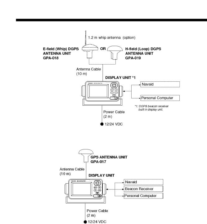
SYSTEM CONFIGURATION
GP-36 System configuration
GP-31 System configuration
v
|
|
|
EQUIPMENT LISTS |
|||
|
|
|
|
|
|
|
Standard supply |
|
|
|
|
|
|
|
|
|
|
|
|
|
Name |
Type |
Qty |
Remarks |
|
|
|
|
|
|
|
|
||
Display Unit |
GP-36 |
1 |
BEACON board incorporated |
Including hanger |
||
|
|
|
|
and knob bolts |
||
|
GP-31 |
No BEACON board |
|
|||
|
|
|
|
|
||
|
|
|
|
|
|
|
Antenna Unit |
GPA-017 |
|
For GP-31, with 10 m cable |
|
|
|
|
|
|
|
|
||
|
GPA-018 |
|
For GP-36, E-field (whip) DGPS antenna, w/10 m |
|||
|
1 |
cable |
|
|
||
|
|
|
|
|||
|
|
|
|
|
||
|
GPA-019 |
|
For GP-36, H-field (loop) DGPS antenna, w/10 m |
|||
|
|
cable |
|
|
||
|
|
|
|
|
||
|
|
|
|
|
||
Installation |
|
1 set |
• Power/Data cable (Type: MJ-A7SPF0005-020, |
|||
Materials |
|
|
Code No.: 000-139-384) |
|
|
|
|
|
|
• Spring washer (1 pc., for whip antenna of |
|||
|
|
|
GPA-018, Type: M10, Code No.: 000-864-261) |
|||
|
|
|
• Tapping screw (4 pcs., for fixing display unit, |
|||
|
|
|
Type: 5X20, Code No.: 000-802-081 |
|||
|
|
|
|
|
|
|
Spare Parts |
|
1 set |
Fuse (2 pcs., Type: FGMG1A, |
|
|
|
|
|
|
Code No.: 000-114-805) |
|
|
|
|
|
|
|
|
|
|
Accessories |
|
1 set |
Hard cover (Type: 20-016-1091, |
|
|
|
|
|
|
Code No.: 100-297-032) |
|
|
|
|
|
|
|
|
|
|
Optional equipment
Name |
Type |
Code No. |
Remarks |
|
|
|
|
|
|
Right Angle |
No.13-QA330 |
000-803-239 |
For antenna |
|
Antenna Base |
|
|
unit |
|
|
|
|
|
|
L-type Antenna |
No.13-QA310 |
000-803-240 |
|
|
Base |
|
|
|
|
|
|
|
|
|
Handrail Antenna |
No.13-RC5160 |
000-806-114 |
|
|
Base |
|
|
|
|
|
|
|
|
|
Mast Mount Kit |
CP20-01111 |
004-365-780 |
|
|
|
|
|
|
|
Cable Assy. |
MJ-A7SPF0005-020 |
000-139-384 |
|
|
|
|
|
|
|
Flush Mount Kit S |
OP-20-17 |
000-040-720 |
For flush mounting the display |
|
|
|
|
unit |
|
Flush Mount Kit F |
OP-20-29 |
000-041-405 |
||
|
||||
|
|
|
|
vi
1.OPERATIONAL OVERVIEW
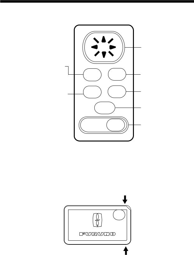
1.1Control Description
Press once: Zoom, centering, or escapes from current operation, depending on display in use.
Press twice: Opens menu.
Selects display mode.
MENU ENT
DISP GOTO
MARK
MOB
DIM
PWR
Figure 1-1 Control panel
Removing the hard cover
Cursor Pad
 Shifts cursor and display.
  Selects items on menus.
Registers items on menus.
Sets/cancels destination.
Inscribes mark, MOB mark on the display.
Long press: Turns power off.
Touch and release: Turns power on. Opens the display for adjustment of dimmer and contrast.
To remove the hard cover, squeeze it at its top and bottom right (or left) corners and pull it toward you.
Pressure
Pressure
1-1

1.2Turning On and Off the Power
Turning on the power
Press the [DIM/PWR] key. The unit beeps and then starts up with the last-used display mode.
Your equipment takes about two minutes to find its position when turned on for the very first time.
The equipment shows receiver status indications at the top left-hand corner in all display modes. Table 1-1 shows these indications and their meanings.
Table 1-1 Receiver status indications
Indication |
Meaning |
|
|
|
|
2D |
Normal 2D GPS position fix |
|
|
|
|
|
GPS position fix with DOP |
|
DOP |
more than 4 (2D position fix) or |
|
|
6 (3D position fix) |
|
|
|
|
3D |
Normal 3D GPS position fix |
|
|
|
|
D2D |
Normal differential GPS |
|
position fix |
||
|
||
|
|
|
D3D |
Normal 3D differential GPS |
|
position fix |
||
|
||
|
|
|
SIM |
Simulation mode. |
|
|
|
DOP: Dilution of Precision. The index for position-fixing accuracy. The higher the number the higher the accuracy of the position fix.
Note: Position accuracy also depends on satellite position.
Turning off the power
Press and hold down the [DIM/PWR] key until the screen goes blank, approx. three seconds. The time remaining until power off is counted down on the display.
1.3Adjusting Display Dimmer and Contrast
1.Press the [DIM/PWR] key with a touch- and-release action. The display shown in Figure 1-2 appears.
D I M M E R ( 1 ~ 8 )
▼  ▲ 4
▲ 4
C O N T R A S T ( 0 ~ 6 3 ) t

 s 4 1
s 4 1
E X I T : [ E N T ]
Figure 1-2 Screen for adjustment of display dimmer and contrast
2.To adjust the dimmer, press ▲ or ▼. Current setting is shown to the right of “▲”.
3.To adjust the contrast, press t or s.
Current setting is shown to the right of
“s”.
4.Press the [ENT] key to finish.
Note: If you turn off the power with minimum contrast,nothing appears on the display when you turn on the power again.Adjust the contrast as described above.
1-2
1.4 Display Modes
Your unit has five display modes: Plotter Display, Highway Display, Steering Display, Nav Data Display and User Display (digital data or speedometer). Press the [DISP] key to select a display mode. Each time the key is pressed, the display mode changes in the sequence shown below.
Figure 1-3 Display modes
Note: Position data can be shown in latitude and longitude or TDs (Loran C or Decca).
1-3
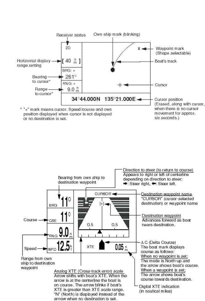
Plotter display
The plotter display traces own ship’s track, and shows position, course, speed, and horizontal display range setting.
Figure 1-4 Plotter display
Highway display
The highway display provides a 3-D view of own ship’s progress toward destination. Nav data is also shown.
Figure 1-5 Highway display
1-4
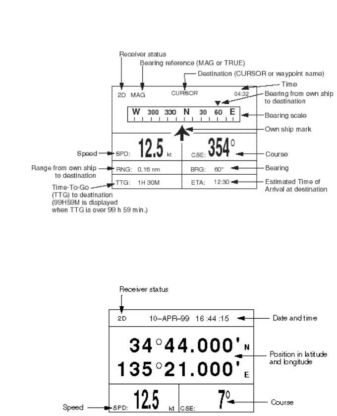
Steering display
The steering display provides steering information such as ship’s speed, course; range, bearing, ETA and TTG (Time-To-Go) to destination.
Figure 1-6 Steering display
Nav data display
The nav data display shows position in latitude and longitude (or TDs), course, speed, date and time.
Figure 1-7 Nav data display
1-5
User displays
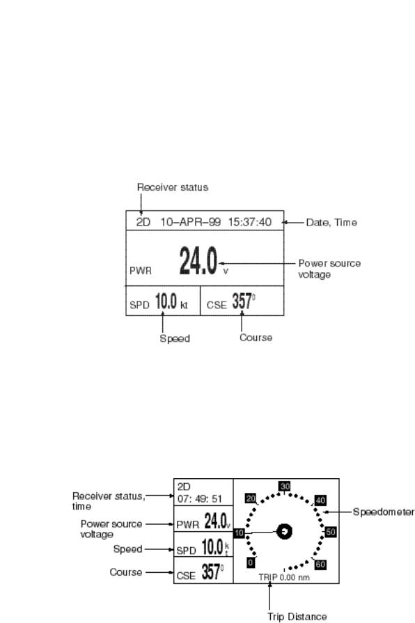
Two user displays are available, digital and speedometer, and the operator may select which to display. The default display is the digital display.
Digital display
The digital display shows digital navigation data. The user may choose what data to display in the three cells below the receiver status, date and time indications. The choices of data are speed, course, range, bearing, time-to-go, estimated time of arrival, trip distance and power source voltage.
Figure 1-8 Digital display
Speedometer display
The speedometer display provides both digital and analog speed readouts. Additionally it provides three cells of data (below the receiver status and time indication) which the user may choose. The choices are the same as those for the digital display.
Figure 1-9 Speedometer display
1-6

1.5 Basic Menu Operation
Most operations of the your unit are carried out through the menu. Below is a quick introduction to how to select a menu and change menu settings. If you get lost in operation, press the [MENU] key to return to the MAIN menu. A complete menu tree appears in the Appendix.
1.Press the [MENU] key once or twice to display the menu.
Figure 1-10 Menu
Once: At the steering display, nav data display, user display.
Twice: At the plotter display, highway display.
2.Operate the cursor pad to select a menu and press the [ENT] key. For example, select PLOTTER and press the [ENT] key.
Figure 1-11 PLOTTER SETUP menu
3.Press ▲ or ▼ to select menu item. For example, select the TRACK REC field.
4.Press the [ENT] key. A window showing options appears. (The figure below shows the options available for TRACK REC.)
Figure 1-12 Options of TRACK REC
5.Press ▲ or ▼ to select option desired.
6.Press the [ENT] key.
7.Press the [MENU] key twice to finish.
How to enter alphanumeric data
In some instances it is necessary to enter alphanumeric or character data. The example below shows how to enter a time difference of –6:30, to use local time instead of UTC time.
1.Press the [MENU] key once or twice to display the menu.
2.Select SYS SETUP and press the [ENT] key.
Figure 1-13 SYS SETUP menu
3.Press ▼ to select the TIME DIFF field.
4.Press the [ENT] key. A cursor circumscribes “+”. This cursor appears whenever selected data can be changed with the cursor pad.
Figure 1-14 SYSTEM SETUP menu, TIME DIFF field selected
1-7
5.Press ▲ to display “–”.
6.Press  to send the cursor to the next digit.
7.Press ▲ or ▼ to display 0.
8.Press  to send the cursor to the next digit.
9.Press ▲ or ▼ to display 6.
10.Press  to send the cursor to the next digit.
11.Press ▲ or ▼ to display 3.
12.Press  to send the cursor to the last digit.
13.Press ▲ or ▼ to display 0.
14.Press the [ENT] key.
15.Press the [MENU] key twice to finish.
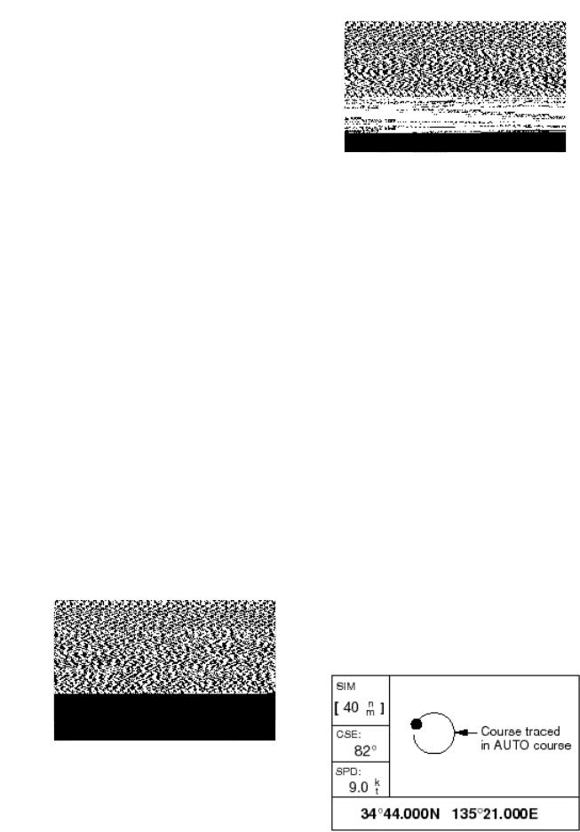
1.6 Simulator Display
The simulator display provides simulated operation of this unit. You may set the speed manually and the course manually or automatically. All controls are operative – you may enter marks, set destination, etc.
1.Press the [MENU] key twice to display the menu.
2.Select SYS SETUP and press the [ENT] key.
Figure 1-16 SIMULATOR menu
4.Press the [ENT] key. A window appears which shows the choices ON or OFF.
5.Select ON and press the [ENT] key.
6.Press the [ENT] key, enter speed to use for the simulation with the cursor pad, and press the [ENT] key.
7.Press the [ENT] key.
8.Select course entry method (AUTO or MANU) and press the [ENT] key. For manual entry of course, press the [ENT] key again, enter course with the cursor pad, and press the [ENT] key again. (The AUTO course tracks a circular course.)
9.Press the [ENT] key, enter latitude (usually current latitude) with the cursor pad, and press the [ENT] key.
10.Press the [ENT] key, enter longitude (usually current longitude), and press the [ENT] key.
11.Press the [MENU] key twice.
12.Select the PLOTTER display with the [DISP] key. SIM appears at the upper left-hand corner when the simulator display is active.
Figure 1-15 SYSTEM SETUP menu
3.Select “SIMULATOR?” and press the [ENT] key.
Figure 1-17 Simulator display, auto course selected
1-8

13.To turn off the simulator display, select OFF at step 5 in this procedure, press the [ENT] key, and press the [MENU] key twice to finish.
Note: If the power is reset while the simulator display is in use, the indication SIMULATION MODE appears at the top of the screen at the next power up, in addition to the indication SIM. SIMULATION MODE disappears when any key is pressed.
1-9
This page is intentionally left blank.
2. PLOTTER DISPLAY OVERVIEW
2.1Enlarging/Shrinking the Display Range
You may increase or decrease the display range on the plotter and highway displays. The horizontal range in the plotter display is available among .02 (40 yd), .05 (101 yd), 0.1 (202 yd), 0.2 (405 yd), 0.5, 1, 2, 5, 10, 20, 40, 80, 160 and 320 nautical miles. (Nautical mile is the default unit of display range. Display range may also be shown in kilometers or miles. Ranges shorter than the value 0.5 are also shown in yards or meters.) The horizontal range in the highway display is available among 0.2, 0.4, 0.8, 1, 2, 4, 8 and 16 nautical miles.
1.Press the [MENU] key. The zoom, ship centering window appears.
2.2 Shifting the Cursor
Use the cursor pad to shift the cursor. The cursor moves in the direction of the arrow or diagonal pressed on the cursor pad.
Cursor state and data
Cursor state determines what data is shown on the display.
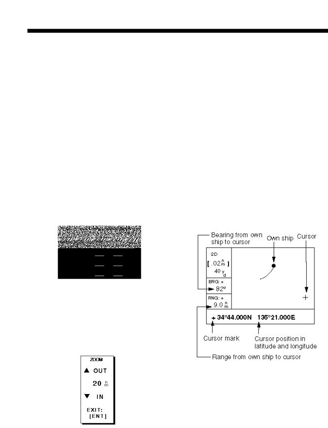
Cursor turned on
Cursor position is displayed in latitude and longitude or TDs (depending on menu setting) at the bottom of the plotter display when the cursor is on. The range and bearing from own ship to the cursor appear at the left-hand side of the display.
Figure 2-1 Zoom, ship centering window
Note: The prompt “SHIP TO CENTER?” does not appear when the highway display mode is active.
2.Press the [ENT] key. The zoom window appears.
Figure 2-2 Zoom window
3.Press ▲ (increase) or ▼ (decrease) to select range desired.
4.Press the [ENT] key to finish.
Figure 2-3 Data displayed on the plotter display when the cursor in on
Cursor turned off
The cursor is erased when there is no cursor pad operation for about six seconds. Ship’s position, speed and course appear at the left side of the plotter display when the cursor is off.
2-1
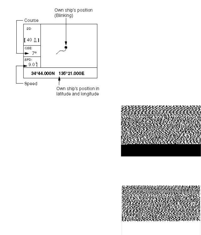
Figure 2-4 Data displayed on the plotter display when the cursor is turned off
2.3 Shifting the Display
The display can be shifted on the plotter display. Operate the cursor pad to place the cursor at an edge of the screen. The display shifts in the direction opposite to cursor pad operation.
2.4Centering Own Ship’s Position
When own ship tracks off the display the own ship mark is automatically returned to the screen center. You can also return it manually as follows:
1.Press the [MENU] key.
2.Select SHIP TO CENTER?.
3.Press the [ENT] key.
2.5Changing Track Plotting Interval, Stopping Plotting of Track
To trace the ship’s track, the ship’s position is stored into the memory at an interval of distance or automatic recording (memory capacity: 1,000 points). For distance, a shorter interval provides better reconstruction of the track, but the storage time of the track is reduced. When the track memory becomes full, the oldest track is erased to make room for the latest.
1.Press the [MENU] key once or twice to display the menu.
Figure 2-5 Menu
2.Select PLOTTER.
3.Press the [ENT] key.
Figure 2-6 PLOTTER SETUP menu
4.The cursor should be on the TRACK REC field. Press the [ENT] key. The track recording method selection window appears.
2-2
Figure 2-7 Track recording method selection window
5.Select OFF, DISTANCE or AUTO and then press the [ENT] key.
OFF: Track is neither recorded or plotted. This setting is useful when you do not need to record track, for example, when returning to port.
DISTANCE: Track is recorded and plotted at the distance interval set. AUTO: Plotting and recording interval changes with chart scale selected.
If you selected DISTANCE, enter the recording interval as follows:
a)Press the [ENT] key.
b)Press  or
or  to select digit to change.
c)Press ▲ or ▼ to change value.
d)Press the [ENT] key after setting.
6.Press the [MENU] key twice to finish.
2.6 Erasing Track
All track can be erased. Track cannot be restored once erased, therefore be absolutely sure you want to erase all track.
1.Press the [MENU] key once or twice to display the menu.
2.Select ERASE and press the [ENT] key to display the ERASE menu.
Figure 2-8 ERASE menu
3.Select “TRACK?” and press the [ENT] key. The message shown in Figure 2-9 appears.
Figure 2-9 Prompt for erasure of track
4.Press the [ENT] key to erase all track.
5.Press the [MENU] key twice to finish.
2-3
This page is intentionally left blank.
3. WAYPOINTS (MARKS)
3.1 Entering Waypoints
In navigation terminology a waypoint is a particular location on a voyage whether it be a starting, intermediate or destination waypoint. Your unit can store 950 waypoints. Waypoints can be entered on the plotter display four ways: at cursor position, at own ship’s position, through the menu (manual input of L/L or TD), and by MOB position.
Entering a waypoint by the cursor
1.On the plotter display, use the cursor pad to place the cursor on the location you want to make a waypoint.
2.Press the [ENT] key. The following window appears.
Figure 3-1 Waypoint name entry window
3.The cursor is on the second line of the display. This is where you may enter waypoint name, which may consist of six characters. (The number shown is the youngest empty waypoint number. If you would rather have the unit register the waypoint under that number, and you do not need to change mark shape or enter a comment, press the [ENT] key twice to register the waypoint and finish.) To enter KOBE as the waypoint name, for example, do the following:
a)Press ▲ or ▼ to display K.
b)Press  to move the cursor to the next column and press ▲ or ▼ to display O.
c)Press  to move the cursor to the next column and press ▲ or ▼ to display B.
d)Press  to move the cursor to the next column and press ▲ or ▼ to display E.
e)Press the [ENT] key. The following window appears.
Figure 3-2 Waypoint position, comment entry window
4.This window is where you can select mark shape, enter a comment, and log the waypoint to a route. (If you do not need to change mark shape, enter a comment, or save waypoint to a route, select “Exit?” and press the [ENT] key to finish.) How to log waypoints to a route will be discussed in the chapter on routes.
a)Use the cursor pad to place the cursor under MARK.
b)Press the [ENT] key.
c)Select mark desired with ▲ or ▼.
Figure 3-3 Mark selection sequence
d) Press the [ENT] key.
3-1
e)The cursor is on the date/time field. Press the [ENT] key.
f)Enter a comment (max. 16 characters) with the cursor pad (the same as you did when entering waypoint name) and press the [ENT] key. To create a space, select “blank” character. To remove all characters which follow the cursor, select the underline.
g)The cursor is on “Exit?.” Press the [ENT] key.
h)Press the [ENT] key again to finish.
Note: “LOG RT?” function is explained in the chapter on routes.
Entering a waypoint at own ship’s position
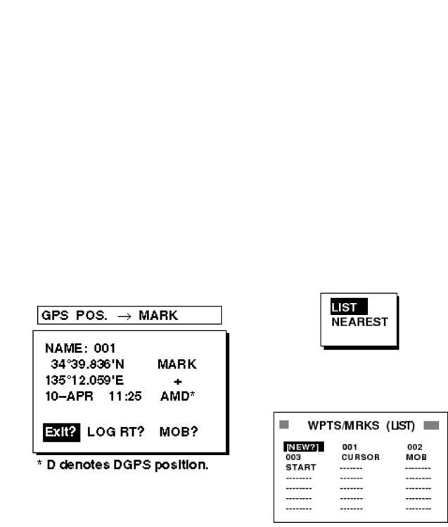
1.Press the [MARK/MOB] key on any display. The following window appears.
5.The cursor is on the date/time field. To change the date to a comment, press the [ENT] key, enter a comment with the cursor pad, and press the [ENT] key again.
6.Place the cursor on “Exit?.” Press the [ENT] key to finish.
Entering a waypoint through the waypoint list
1.Press the [MENU] key once or twice to display the menu.
2.Select WAYPOINTS.
3.Press the [ENT] key. The following window appears. Select LIST. (NEAREST displays waypoints from nearest to furthest; however, waypoints cannot be entered from this display.)
Figure 3-5 Waypoint list selection window
4.Press the [ENT] key. The WPTS/MRKS list appears.
Figure 3-4 Own ship’s position window
2.If you want to register the waypoint under the number shown, and you do not need to change mark shape, enter a comment, or log the waypoint to a route, press the [ENT] key to finish.
3.To change name, select the NAME field, press the [ENT] key, select name with the cursor pad, and press the [ENT] key.
4.To change mark shape, place the cursor under MARK. Press the [ENT] key, select mark shape with the cursor pad, and press the [ENT] key again.
Figure 3-6 WPTS/MRKS list
CURSOR: Cursor position when destination is set with cursor. MOB: Man overboard position.
START: Starting point when destination is selected.
5.The cursor is on NEW. Press the [ENT] key.
3-2
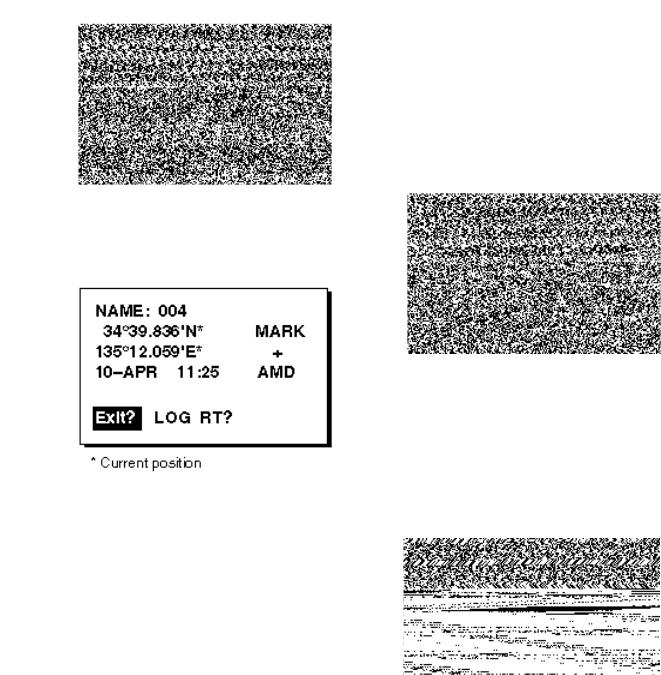
Figure 3-7 Screen for entering waypoint name
6.Enter name (if desired) with the cursor pad and press the [ENT] key.
Figure 3-8 Screen for entering waypoint latitude and longitude
7.Use the cursor pad to place the cursor on the second line (latitude or TD) and press the [ENT] key. Enter latitude (TD) and press the [ENT] key.
8.Press the [ENT] key, enter longitude (TD) in similar fashion as you did with latitude and press the [ENT] key.
Note: To enter position by TDs, see paragraph 7.7 “Displaying Position in TDs.”
9.To change mark shape, select mark shape currently shown and press the [ENT] key. Select mark desired with the cursor pad and press the [ENT] key.
10.To change date and time to the comment of your choice, press the [ENT] key, enter comment, and press the [ENT] key again.
11.Place the cursor on “Exit?.” Press the [ENT] key.
12.Press the [MENU] key twice to finish.
3.2 Entering the MOB Mark
The MOB mark denotes man overboard position. Only one MOB mark may be entered. Each time the MOB mark is entered the previous MOB mark and its position data are written over.
1. Press the [MARK/MOB] key.
Figure 3-9 MOB window
2. Press  to select “MOB?.”
Note: Pressing the [ENT] key instead of  at step 2 saves the position as a waypoint. “LOGRT?” function is explained in the chapter on routes.
3. Press the [ENT] key.
Figure 3-10 MOB window-2
4.To set MOB position as destination, press the [ENT] key. Then, the plotter display marks MOB position as shown in Figure 3-11.
Note: Selecting “NO” and pressing the [ENT] key at step 4 saves the position as a waypoint.
3-3
Loading...