


 Loading...
Back
Installation Manual
COLOR SCANNING SONAR FSV-24/24S
SAFETY INSTRUCTIONS ........................................................................... |
i |
||
SYSTEM CONFIGURATION ..................................................................... |
iii |
||
EQUIPMENT LISTS ................................................................................... |
v |
||
1. |
MOUNTING THE EQUIPMENT........................................................ |
1-1 |
|
1.1 |
Mounting the Hull Unit...................................................................................................... |
1-1 |
|
1.2 |
Mounting the Display Unit ................................................................................................ |
1-8 |
|
1.3 |
Mounting the Transceiver Unit........................................................................................ |
1-14 |
|
1.4 |
Mounting the Power Supply Unit .................................................................................... |
1-14 |
|
1.5 |
Grounding the Equipment .............................................................................................. |
1-15 |
|
1.6 |
Installing Attachment Flange (option) ............................................................................. |
1-15 |
|
1.7 |
Mounting the Cable for Extension Kit (option) ................................................................ |
1-18 |
|
1.8 Attachment Kit (option)................................................................................................... |
1-19 |
||
2. |
WIRING............................................................................................ |
2-1 |
|
2.1 |
How to Use the Crimping Tool, Pin Extractor.................................................................... |
2-1 |
|
2.2 |
Location of Connectors .................................................................................................... |
2-2 |
|
2.3 |
Monitor Unit ..................................................................................................................... |
2-4 |
|
2.4 |
Processor Unit ................................................................................................................. |
2-8 |
|
2.5 |
Transceiver Unit ............................................................................................................. |
2-14 |
|
2.6 |
Power Supply Unit ......................................................................................................... |
2-17 |
|
2.7 |
Cable for Extension Kit................................................................................................... |
2-17 |
|
3. |
ADJUSTMENT AND CHECK........................................................... |
3-1 |
|
3.1 |
Hull Unit Check ................................................................................................................ |
3-1 |
|
3.2 |
Heading Adjustment......................................................................................................... |
3-4 |
|
3.3 |
Configuring Own Ship Mark ............................................................................................. |
3-6 |
|
3.4 Other SYSTEM Menu Items............................................................................................. |
3-8 |
||
3.5 |
CONE Board Setting in the Processor Unit .................................................................... |
3-12 |
|
3.6 |
DIP Switch Setting ......................................................................................................... |
3-13 |
|
3.7 |
Testing TX/RX Independently at hull unit........................................................................ |
3-15 |
|
4. CONNECTING THE EXTERNAL INTERFACE CS-120A |
................. 4-1 |
||
Check List............................................................................................ |
AP-1 |
||
PACKING LISTS .................................................................................... |
A-1 |
||
OUTLINE DRAWINGS ........................................................................... |
D-1 |
||
INTERCONNECTION DIAGRAMS......................................................... |
S-1 |
||
|
|
|
|
|
|
|
|
www.furuno.co.jp
The paper used in this manual is elemental chlorine free.
9-52 Ashihara-cho,
Nishinomiya, 662-8580, JAPAN
Telephone : +81-(0)798-65-2111
Fax |
: +81-(0)798-65-4200 |
All rights reserved. |
Printed in Japan |
Pub. No. IME-13180-L
(YOSH ) FSV-24/24S
FURUNO Authorized Distributor/Dealer
A : APR . 2001
L : JUN . 15, 2007
*00080916714*
*00080916714*
* 0 0 0 8 0 9 1 6 7 1 4 *

 SAFETY INSTRUCTIONS
 DANGER
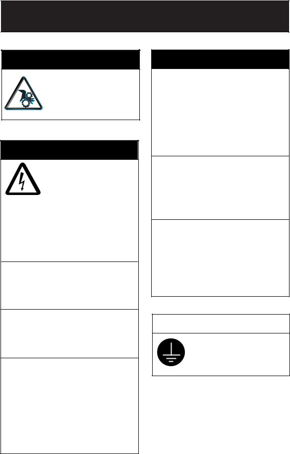
Keep away from moving shaft of the hull unit.
Gears may cause injury.
 WARNING
Do not open the cover unless totally familiar with electrical circuits and service manual.
High voltage exists inside the equipment, and a residual charge remains in capacitors several minutes after the power is turned off. Improper handling can result in electrical shock.
Turn off the power at the switchboard before beginning the installation.
Fire or electrical shock can result if the power is left on.
Do not install the equipment where it may get wet from rain or water splash.
Water in the equipment can result in fire, electrical shock or equipment damage.
Be sure no water leaks in at the transducer installation site.
Water leakage can sink the vessel. Also confirm that the transducer will not loosen by ship's vibration. The installer of the equipment is solely responsible for the proper installation of the equipment. FURUNO will assume no responsibility for any damage associated with improper installation.
 WARNING
Install the specified transducer tank in accordance with the installation instructions. If a different tank is to be
installed the shipyard is solely responsible for its installation, and it should be installed so the hull will not be damaged if the tank strikes an object.
The tank or hull may be damaged if the tank strikes an object.
If a steel tank is installed on a wooden or FRP vessel, take appropriate measures to prevent electrolytic corrosion.
Electrolytic corrosion can damage the hull.
Be sure that the power supply is compatible with the voltage rating of the equipment.
Connection of an incorrect power supply can cause fire or equipment damage. The voltage rating of the equipment appears on the label above the power connector.
 CAUTION
Ground the equipment to prevent electrical shock and mutual interference.
i

 CAUTION
Maximum speed while the transducer is projected and being raised or lowered is as below, to prevent damage to the transducer.
|
Projected |
Raising/ |
|
|
Lowering |
|
|
|
1200 mm stroke |
Max. 18 kt |
Max. 15 kt |
|
|
|
1600 mm stroke |
Max. 15 kt |
Max. 12 kt |
|
|
|
Observe the following compass safe distances to prevent interference to a magnetic compass:
|
Standard |
Steering |
|
compass |
compass |
|
|
|
Processor Unit |
1.55 m |
1.05 m |
|
|
|
Control Unit |
0.20 m |
0.15 m |
|
|
|
Monitor Unit |
1.25 m |
0.85 m |
|
|
|
Other equipment should be positioned at least 7 m away from a magnetic compass.
ii

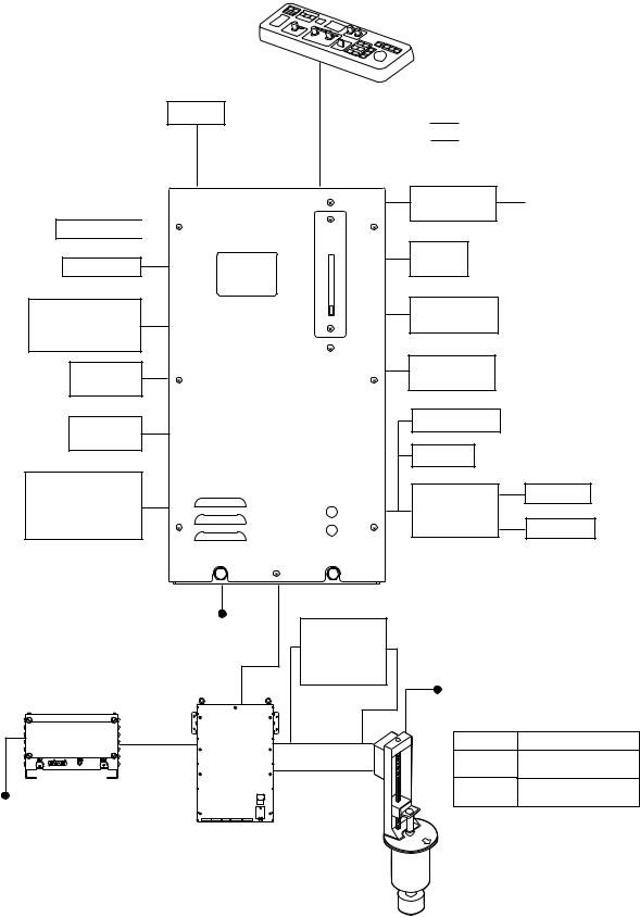
SYSTEM CONFIGURATION
Standard type
MONITOR |
CONTROL UNIT |
|
FSV-2401 |
||
UNIT |
||
|
||
FSV-2400 |
|
Local Supply
Option
AD Converter |
Gyrocompass |
|
AD-10 |
||
|
||
Loudspeaker |
|
|
Current |
|
|
Indicator |
|
|
Sub Monitor |
|
Current Echo Sounder, Indicator/Log
Current Indicator, other
|
PROCESSOR UNIT |
E/S Interface |
|
Navigator 1 |
VI-1100A |
|
|
|
|
||
FSV-2402 |
|
|
|
|
|
|
|
|
|
Net Recorder |
|
Navigator 2 |
|
VI-1100A |
|
|
|
|
|
External |
|
Net Sonde |
VI-1100A |
Interface CS-120A |
|
Junction Box |
|
(already installed) |
|
CS-170 |
Net Sonde |
Note 1 |
|
|
|
|
100/110/115/ |
|
|
|
|
|
220/230 VAC, |
Cable for |
|
|
|
|
1φ, |
50/60 Hz |
|
|
|
|
Extension Kit |
|
|
||
POWER |
TRANSCEIVER |
|
|
||
FSV-2451 |
|
|
|||
SUPPLY |
|
|
|||
|
UNIT |
FSV-2452 |
|
|
|
UNIT |
|
|
|
||
|
FSV-241E |
220 VAC, |
|
||
FSV-242 |
|
|
3φ, |
50/60 Hz |
|
|
|
|
|
Hull unit |
Specifications |
|
|
|
|
FSV-247 1200 mm stroke |
|
|
|
|
HULL UNIT |
FSV-248 |
1600 mm stroke |
100/110/115/ |
|
220/230 VAC, |
|
1φ, 50/60 Hz |
Note 1: Power Kit FSV-2403 (option, installed in |
|
processor unit) required to connect CS-120A. |
iii
Black box type
Monitor
Loudspeaker 
Sub Monitor
Echo Sounder, Current Indicator, other
Navigator 1 |
PROCESSOR UNIT |
FSV-2402
Navigator 2
External
Interface CS-120A (already installed) Note 1
|
100/110/115/ |
|
|
|
220/230 VAC, |
Cable for |
|
POWER |
1φ, 50/60 Hz |
Extension Kit |
|
TRANSCEIVER |
FSV-2451 |
||
SUPPLY |
|||
FSV-2452 |
|||
UNIT |
UNIT |
||
|
|||
FSV-242 |
FSV-241E |
|
|
HULL UNIT |
100/110/115/ |
(Select one.) |
|
|
220/230 VAC, |
|
1φ, 50/60 Hz |
Note 1: Power Kit FSV-2403 (option, installed in |
|
processor unit) required to connect CS-120A. |
CONTROL UNIT
FSV-2401
Local Supply
Option
AD Converter |
Gyrocompass |
|
AD-10 |
||
|
||
Current |
|
|
Indicator |
|
|
Current |
|
|
Indicator/Log |
|
|
E/S Interface |
|
|
VI-1100A |
|
|
Net Recorder |
|
|
VI-1100A |
|
|
Net Sonde |
VI-1100A |
|
Junction Box |
|
|
CS-170 |
Net Sonde |
220 VAC,
3φ, 50/60 Hz
Hull unit |
Specifications |
FSV-247 1200 mm stroke
FSV-248 1600 mm stroke
iv

EQUIPMENT LISTS
Standard supply
Name |
Type |
Code No. |
Q’ty |
Remarks |
|
Monitor Unit |
FSV-2400 |
- |
1 |
21” color monitor |
|
Control Unit |
FSV-2401 |
- |
1 |
w/cable |
|
Processor Unit |
FSV-2402 |
- |
1 |
For FSV-24 |
|
FSV-2402S |
|
For FSV-24S |
|
||
|
|
|
|
||
Transceiver Unit |
FSV-241E |
- |
1 |
|
|
Power Supply Unit |
FSV-242 |
- |
1 |
|
|
Hull Unit |
FSV-247 |
- |
1* |
1200 mm stroke |
|
FSV-248 |
- |
1600 mm stroke |
|
||
|
|
|
|||
|
|
|
|
For system with monitor |
|
|
|
|
|
CP10-04501, 10S2074, |
|
|
CP10-05100 |
000-067-027 |
|
CP10-04502, CP10-04503, |
|
|
|
|
|
CP10-04505, CP10-04506, |
|
|
|
|
|
10S2078 |
|
|
|
|
|
For system with monitor |
|
Installation Materials |
CP10-05110 |
000-067-028 |
1 set* |
CP10-04501, 10S2075, |
|
|
|
CP10-04502, CP10-04503, |
|
||
|
|
|
|
CP10-04505, CP10-04506, |
|
|
|
|
|
10S2078 |
|
|
|
|
|
For system without monitor |
|
|
CP10-05120 |
000-067-029 |
|
CP10-04502, CP10-04503, |
|
|
|
CP10-04505, CP10-04506, |
|
||
|
|
|
|
|
|
|
|
|
|
10S2078 |
|
Spare Parts |
SP10-02600 |
000-066-999 |
1 set |
SP10-02601, SP1-02602, |
|
SP10-02603 |
|
||||
|
|
|
|
|
|
|
|
|
|
FP03-06201, FP10-02202, |
|
Accessories |
FP10-02200 |
000-067-006 |
1 set |
FP10-02201, FP10-02203, |
|
|
|
dust cover |
|
||
|
FP10-02210 |
000-067-007 |
|
For system without monitor |
|
|
|
|
|
FP10-02201, FP10-02203 |
|
|
|
|
|
*: Select one |
|
v
Options
Name |
Type |
Code No. |
Q’ty |
Remarks |
|
Monitor Unit |
FSV-2400-10 |
|
|
With CP10-04501, |
|
|
|
- |
|
FP03-06201, FP10-02202, |
|
|
|
|
Dust cover & 10S5207 (10 m |
||
|
|
|
|
||
|
|
|
1 |
cable) |
|
|
FSV-2400-30 |
|
With CP10-04501, |
||
|
|
|
|||
|
|
- |
|
FP03-06201, FP10-02202, |
|
|
|
|
Dust cover & 10S2075 (30 m |
||
|
|
|
|
||
|
|
|
|
cable) |
|
Control Unit |
FSV-2401-E-5 |
- |
|
With FP10-02201 & 5 m |
|
|
|
1 |
cable |
||
|
|
|
|||
|
FSV-2401-E-10 |
- |
With FP10-02201 & 10m |
||
|
|
||||
|
|
|
cable |
||
|
|
|
|
||
37 cores Cable |
10S1258 |
000-101-006 |
1 |
Specify length |
|
E/S Interface |
VI-1100A |
- |
1 |
|
|
Net Zonde Junction |
CS-170 |
- |
1 |
For sonde connection |
|
Box |
|
|
|
|
|
Power Supply Kit |
FSV-2403 |
000-067-013 |
1 |
For connection of |
|
CS-120A |
|||||
|
|
|
|
||
NMEA Cable |
MJ-A6SPF0012-100C |
000-154-037-10 |
1 |
10 m, 6P-6P |
|
|
MJ-A6SPF0012-050C |
000-154-053-10 |
1 |
5 m, 6P-6P |
|
E/S cable |
VVS 0.3X8C *6M* |
000-555-043 |
1 |
6 m |
|
|
OP10-22 |
000-067-037 |
1 |
For CSH-20 1200 mm |
|
Attachment Flange |
stroke w/flange, FSV-247 |
||||
|
|
|
|||
OP10-23 |
000-067-038 |
1 |
For CSH-20 1600 mm |
||
|
|||||
|
stroke w/flange, FSV-248 |
||||
|
|
|
|
||
|
|
|
|
Using retraction tank of |
|
Attachment Kit |
OP10-24 |
006-943-530 |
1 |
FSV-243E/244E for |
|
|
|
|
|
FSV-247/248 |
|
Loudspeaker |
SEM-21Q |
000-144-917 |
1 |
|
|
Hood |
FP03-06503 |
008-490-970 |
1 |
For monitor unit |
|
Installation Material |
CP10-04801 |
006-934-240 |
1 |
|
|
for interface |
|
||||
|
|
|
|
||
Cable for |
|
|
|
5 m cable extension, |
|
Extension Kit |
FSV-2451 |
000-067-030 |
|
10S2138*5m*, |
|
|
|
10S2139*5m*, |
|||
|
|
|
|
||
|
|
|
1 |
10S2144*12.9m* |
|
|
|
|
15 m cable extension, |
||
|
|
|
|
||
|
FSV-2452 |
000-067-031 |
|
10S2138*15m*, |
|
|
|
10S2139*15m*, |
|||
|
|
|
|
||
|
|
|
|
10S2145*22.9m* |
vi
1.MOUNTING THE EQUIPMENT
1.1Mounting the Hull Unit
Note1) The rise/lower control box of the hull unit contains motion sensor. Therefore, never drop the hull unit.
Note2) Take care the handling of the transducer. Do not give a strong shock.
1.1.1Location of hull unit
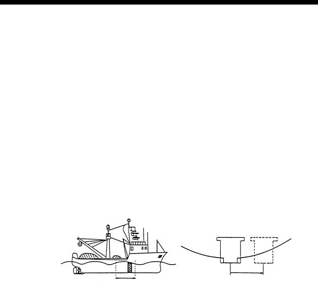
Decide the location of the hull unit through consultation with the dockyard and ship owner. When deciding the location, the following points should be taken into account.
•Select an area where propeller noise, cruising noise, air bubbles and interference from turbulence are at a minimum. Generally, the point at 1/3 to 1/2 of the ship’s length from the bow on or near the keel is optimum. On-the-keel installation is advantageous for minimizing oil consumption in comparison with off-the-keel. If the hull unit can not be installed on the keel, the center of the retraction tank should be within 600 mm of the keel to prevent a rolling effect. For large ship with deep draft, the hull unit can be installed at the bow.
1/2 |
1/3 |
Within 600 meter |
|
|
Hull unit mounting location
•Select a place where the hull bottom is flat and the draft is sufficiently deep. Normally, the transducer should protrude at least 500 mm beyond the keel to minimize the effect of air foam and bubbles.
•Select a place where interference from other equipment is minimal. The hull unit should be at least 2.5 m away from the transducers of other equipment.
•No obstacle should be in the fore direction since it causes a shadow zone and aerated water, resulting in poor sonar performance.
•The space shown in the figure on the next page is required around the hull unit for wiring and maintenance.
•If the ambient temperature of the unit is below 0° C, provide the sonar compartment with a heater to keep the temperature above 0° C.
1-1
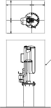
1300 |
650 |
1000 |
|
600 |
|
Heater Insulator
Maintenance space, example sonar compartment
Note: After mounting the equipment, install stays for anti-vibration. See page 1-7.
1-2
1.1.2Shortening the retraction tank
The retraction tank is 1300 mm in length when supplied. Shorten the tank as necessary so that the transducer is placed well below the keel when it is fully lowered. The following table provides guidelines for shortening the tank. Refer also to the retraction tank installation drawing at the back of this manual.
Installation
Method
XDCR Travel |
D |
D |
|
|
|
Remove 130 |
Remove 130 to 140 mm |
|
|
|
thru 140 mm |
from the bottom. |
|
|
1200 mm |
from the |
Same as left. Note that the length |
Same as left. |
|
bottom. |
||||
stroke |
"D" must be less than |
|
||
|
1170 mm. |
|
||
|
|
|
|
Remove |
|
Remove less than |
|
|
|
|
140 mm from the |
|
||
|
less than |
|
Same as left. |
||
|
|
bottom. Note that the |
|||
1600 mm |
140 mm |
Same as left. |
|||
length "D" must be less |
|
||||
from the |
|
||||
stroke |
|
than 1570 mm. |
|
||
|
bottom. |
|
|
||
|
|
|
|
Guidelines for shortening the retraction tank
Note 1: In the 1200 mm stroke type hull unit, the transducer will not fully protrude unless the tank is shortened by at least 130 mm from the bottom, and cannot be fully retracted if more than 140 mm is removed.
Note 2: In the 1600 mm stroke type hull unit, the transducer cannot be fully retracted if the tank is removed more than 140 mm.
Note 3: When 140 mm is removed and “D” is minimum, the effect of air foam is minimized because the transducer fully protrudes in water.
1-3
1.1.3Remarks for installation of retraction tank
1.Make, if possible, the installation location a double bottom structure.
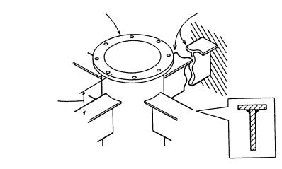
2.Install, if possible, the tank on the keel where the tank can be most firmly fixed.
3.Install the reinforcement ribs as near as possible to the top of the retraction tank, allowing space for tightening of bolts and nuts.
Retraction tank |
Reinforcement rib |
250-300 mm
How to install reinforcement ribs
4.Add a doubling plate at the location where the retraction tank is welded to the hull bottom. The size of the doubling plate is normally 1300 mm in diameter so that it may lie across two bottom frames.
5.Make the bow mark on the attachment flange with a chisel.
1-4
1.1.4Installing hull unit on retraction tank
After welding the retraction tank and allowing sufficient time for cooling, install the hull unit as follows.
1.Clean the hull unit flange, the O-ring and O-ring groove. Coat them with a slight amount of grease. Place the O-ring in position on the tank flange.
2.Orient the hull unit so that the bow mark (inscribed) on its flange points toward the ship’s bow. Note that heading adjustment in the display unit is required if the bow mark does not face the ship’s bow.
3.Confirm that the O-ring is in position. Place the hull unit on the tank.
4.Coat every bolt, washer and nut with a slight amount of grease to ease removal. Fasten the hull unit to the retraction tank with flat washers, spring washers and hex bolts.
5.Reinforce the hull unit against vibration by extending stays to the ship’s hull from the two eye bolts at the top of the hull unit, referring to the figure at the top of page 1-7.
1-5
Hex. Nut
Spring Washer
Flat Washer
Bow Mark
Hull Unit Flange
O-ring
Tank Flange
Flat Washer
Hex. Bolt
|
Hex. Nut |
Spring Washer |
|
O-ring |
|
|
Flat Washer |
|
O-ring |
|
Retraction Tank |
Flat Washer |
|
Hex. Nut |
Hex. Bolt |
|
|
Spring Washer |
|
Stern side (seven locations) |
Bow side (17 locations) |
Installation of hull unit
1-6
1.1.5Installing stays (anti-vibration measure)
Install stays from the top of the hull unit to the ship’s hull. The stays should be angle iron with a size of 75X75X9 mm or more and at least two pieces should be used; one each to ship’s bow and stern directions. Install if possible, two more stays in ship’s transverse direction.
Bow
Stay
Stay
Hull Unit
Proper installation of stays
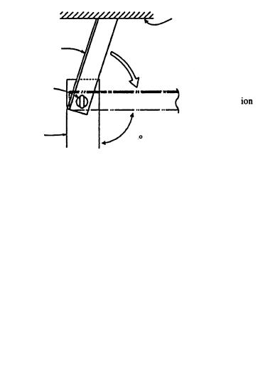
Do not install the stays as shown below. Vibration-resistance effect is reduced since vibration is applied to the stays as rotation force. Install them horizontally.
|
Crossbeam |
|
on ceiling |
Stay |
(wrong installation method) |
Eye Bolt
Proper installation
Hull Unit |
90 |
|
|
|
Proper and wrong installation of stay |
Note: Install stays as shown above, otherwise the transducer may be damaged.
1-7
1.2Mounting the Display Unit
The display unit is composed of the processor, monitor and control units.
1.2.1Processor unit
Mounting considerations
When selecting a mounting location, keep in mind the following points:
•The processor unit must be mounted upright.
•Locate the unit out of direct sunlight and away from heat sources because of heat that can build up inside the cabinet.
•Locate the equipment away from places subject to water splash and rain.
•Be sure the mounting location is strong enough to support the weight of the unit under the continued vibration which is normally experienced on the ship. If necessary reinforce the mounting location.
•Determine the mounting location considering the length of the cables below.
a)Signal cable from the transceiver unit
b)Monitor cable from the monitor
c)Control cable from the control unit (when locally supplied monitor is used)
•Leave sufficient space on the sides and rear of the unit to facilitate maintenance. Also, leave a foot or so of "service loop" in cables behind the unit so it can be pulled forward for servicing or easy removal of connectors.
•Make free space of 400 mm between the processor unit and bulkhead to prevent cable stress.
Cable fixing hole
1-8
Mounting procedure
1.Unfasten two bolts from the bottom of the front side of the processor unit, and pull the unit toward you to separate the unit from the mounting base.
2.Fasten six bolts (M6x20, supplied as installation material) to install the mounting base.
3.Place the processor unit in front of the mounting base.
4.Push the unit forward until it touches the end of the mounting base.
5.Refasten two bolts removed at step 1 to fix the unit.
5.5 |
505 |
477 |
|
160+1 |
|
34 |
8 |
|
200+1 195+1 |
Front view |
Top view |
Processor unit
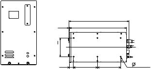
1.2.2Monitor unit
Mounting considerations
•The monitor unit is designed for mounting on a tabletop.
•Locate the monitor unit where it can be easily operated while viewing the screen and operating the control unit.
•Locate the monitor unit out of direct sunlight and away from heat sources because of heat that can build up inside the cabinet.
•Locate the equipment away from places subject to water splash and rain.
•Be sure the mounting location is strong enough to support the weight of the unit under the continued vibration which is normally experienced on the ship. If necessary reinforce the mounting location.
•The length of the monitor cable which runs between the processor unit and the monitor unit is 10 m. Keep this distance in mind when selecting a mounting location.
•Leave sufficient space on the sides and rear of the unit to facilitate maintenance.
1-9
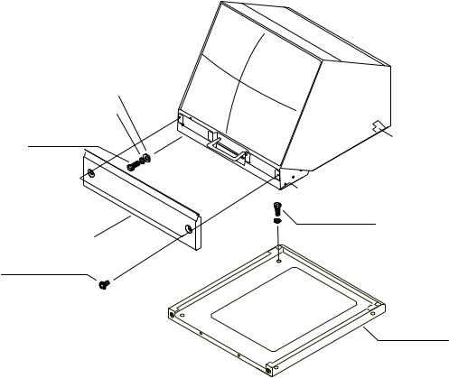
Mounting procedure
1.Drill four holes of 12 mm in diameter in the mounting location, referring to the outline drawing for mounting dimensions.
2.Unfasten two M4X10 screws to dismount the front cover.
3.Unfasten two sets of M10 bolts, plain washers and spring washers to separate the monitor from the mounting base.
4.Pull the monitor forward about four centimeters and then lift it to separate it from the mounting base.
5.Fasten the mounting base to the mounting location with M10 bolts, nuts and washers (local supply).
6.Lay the monitor on the top of the mounting base, making sure the rear pin on the monitor is mated to the slit in the mounting base. Fix the monitor to the mounting base with the two sets of bolts, nuts and washers unfastened at step 3.
7.Close the front cover.
Plain Washer, M10, 2 pcs.
Spring Washer, M10, 2 pcs.
Hex Bolt M10X30, 2 pcs.
Front Cover
Pan-Head Screw
M4X10, 2 pcs.
Pin
Hex Bolt
M10X30, 4 pcs.
Washer
 Slit
Slit
Mounting Base
Monitor unit
1-10
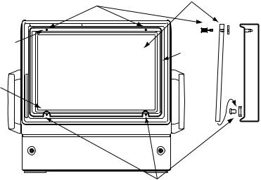
Attaching the CRT filter
1.Attach two spacer (5x2.5, supplied) with screws (M5x10, supplied) to the location shown below.
2.Screw two hood retainer (supplied) into the filter (supplied).
3.Turn two washers (Ф12, supplied) into two hood retainer attached at step 2.
4.Attach the filter to the monitor unit as shown below.
Hood retainer (2 pcs.) |
Filter |
Washer (2 pcs.) |
|
M5 |
|
tapping hole |
CRT |
(Up side) |
|
Notch |
|
(Down side) |
|
Spacer (2 pcs.)
Screw (2 pcs.)
How to attach the hood
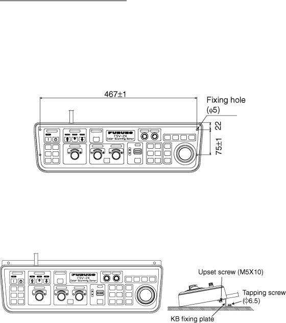
1.2.3Control unit
The control unit may be mounted on a tabletop, with or without the KB fixing plate (supplied), which mounts the control unit at an angle. If the control unit is not to be fastened, lay it atop the rubber feet (supplied as accessory).
(1) Rubber feet
Attach four rubber feet to the bottom of the control unit if it is not going to be permanently fixed.
1-11
(2)Fixing without KB fixing plate
1)Drill four mounting holes of 6 mm diameter to fasten the control unit, referring to the outline drawing at the back of this manual.
2)Make a cutout in the mounting location large enough to accommodate the name plate so the control unit will lie flat. For dimensions, see the outline drawing at the back of this manual.
3)Fix the control unit with four bolts (M5) from under the tabletop. (M5 bolts with a sufficient length for the thickness of the tabletop should be provided locally.)
Control unit
(3) Using KB fixing plate mounting
1.To fix the control unit to a desired location at an angle, fasten the KB fixing
plate to the control unit and desired location with two upset screws (M5X10, supplied) and two tapping screws (φ 6.5, local supply) as below.
How to attach KB fixing plate
2. Set dust cover (supplied) to the control unit.
1-12
Passing the cable through the bottom of the control unit
For permanent mounting ((2) and (3) above), the control cable can be passed through the bottom of the control unit. Do the steps in below.
1.Unfasten eight screws (M4) to remove the cover from the bottom of the control unit.
2.Unscrew two screws (M4x10) to remove the cable clamp.
3.Disconnect two connectors J1 and J2 from the circuit board.
4.Attach the cable to the control unit cover with the cable clamp (removed at step 2), two flat head screws (M4), flat washers, spring washers and nuts (hardware: supplied).
Screw
M4X8 (8 pcs.)
Control |
unit |
|
|
cover |
|
|
|
Previous cable hole
Clamp |
Nut |
|
Spring washer |
||
|
||
|
Flar washer |
|
|
Flat head screw |
Fasten the cable with the clamp here.
Control unit, cover removed
5.Re-connect two connectors (disconnected at step 3) to the previous locations.
6.Fasten eight screws to attach the control unit cover.
7.Attach the connector seal (supplied) to the hole at the rear of the control unit.
8.Drill a hole to pass the cable from the bottom of the control unit through the tabletop. The diameter of the hole should be 30 mm.
9.Attach the connector seal (supplied) to the hole at the bottom of the control unit when the above modification is not done.
10.Fix the control unit referring to (2) or (3) on the previous page.
|
|
|
|
|
|
|
|
Cable |
|
|
|
|
|
|
|
|
|
|
|
|
|
|
|
|
|
|
|
|
|
|
|
|
|
|
|
|
|
|
|
Cable |
||||
w/o KB fixing plate |
w/ KB fixing plate |
|||||||
Control unit, side view
1-13
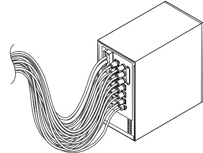
1.3Mounting the Transceiver Unit
The transceiver unit should be mounted on a mounting base (shipyard supply) whose dimensions are as shown in the outline drawing of the transceiver unit at the back of this manual. The transceiver unit should be reinforced against vibration by stays extending from the eyebolts on the top of the unit. Fasten 10 bolts (M12, local supply) at the bottom and back of the transceiver unit to fasten it to the mounting location.
Transceiver unit
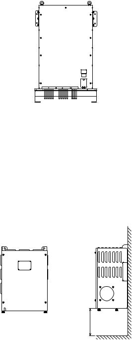
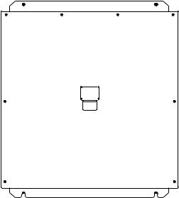
1.4Mounting the Power Supply Unit
Weld four bolts (M8, local supply) referring to the outline drawing at the back of this manual. Sets the power supply unit to the bolts welded, and then turn four nuts (local supply) to fix.
Note: If necessary, reinforce the bulkhead since the unit weights 25 kg (57.3 lbs).
150
Power supply unit
1-14

1.5Grounding the Equipment
The power supply unit, processor unit and hull unit have protective grounding. Ground the units with a ground wire (IV-8SQ, local supply) or copper strap to prevent electrical shock. Ground the monitor unit and transceiver unit with a ground wire (IV-8SQ, local supply) or copper strap fastened to the ship’s superstructure. For the power supply unit, transceiver unit and junction box (option) use a supplied copper strap.
Grounding for junction box
Use one of four butterfly bolts to ground the junction box.
1.6Installing Attachment Flange (option)
The tank for the CSH-20 series may be used by installing the optional attachment flange.
In case that 1200 mm stroke was used in CSH-20 series |
|
|
||
Attachment flange set |
|
|
|
|
For FSV-247: OP10-22 (Code no: 000-067-037) |
|
|
||
Name |
Type |
Code No. |
Q’ty |
Remarks |
Attachment flange |
10-077-5801 |
100-303-601 |
1 |
|
O-ring |
CO 0318A (V585) |
000-166-370-10 |
1 |
|
Hex. bolt |
M20x120 SUS304 |
000-162-825-10 |
24 |
|
Hex. nut |
M20 SUS304 |
000-863-116 |
48 |
|
Flat washer |
M20 SUS304 |
000-864-136 |
48 |
|
Spring washer |
M20 SUS304 |
000-864-270 |
24 |
|
In case that 1600 mm stroke was used in CSH-20 series |
|
|
||
Attachment flange set |
|
|
|
|
For FSV-248: OP10-23 (Code no. 000-067-038) |
|
|
||
Name |
Type |
Code No. |
Q’ty |
Remarks |
Attachment flange |
10-077-5802 |
100-303-610 |
1 |
|
O-ring |
CO 0318A (V585) |
000-166-370-10 |
1 |
|
Hex. nut |
M20 SUS304 |
000-863-116 |
48 |
|
Flat washer |
M20 SUS304 |
000-864-136 |
24 |
|
Spring washer |
M20 SUS304 |
000-864-270 |
24 |
|
1-15
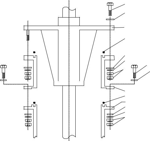
Procedure
1.Clean the hull unit flange, O-ring and O-ring groove. Coat them with a slight amount grease.
2.(1200 mm stroke) Use 24 hex. bolts, 48 hex nuts, flat washers and spring washers to fasten the attachment flange to retraction tank.
(1600 mm stroke) 24 bolts have already been fitted. Use the bolts, 48 hex. nuts, flat washers and spring washers to fasten the attachment flange to retraction tank.
3.Place the O-ring in position on the attachment flange.
To install the attachment flange and the hull unit, see “1.1.4 Installing hull unit on retraction tank” on page 1-5.
The sectional view for the attachment flanges are shown on the next two pages.
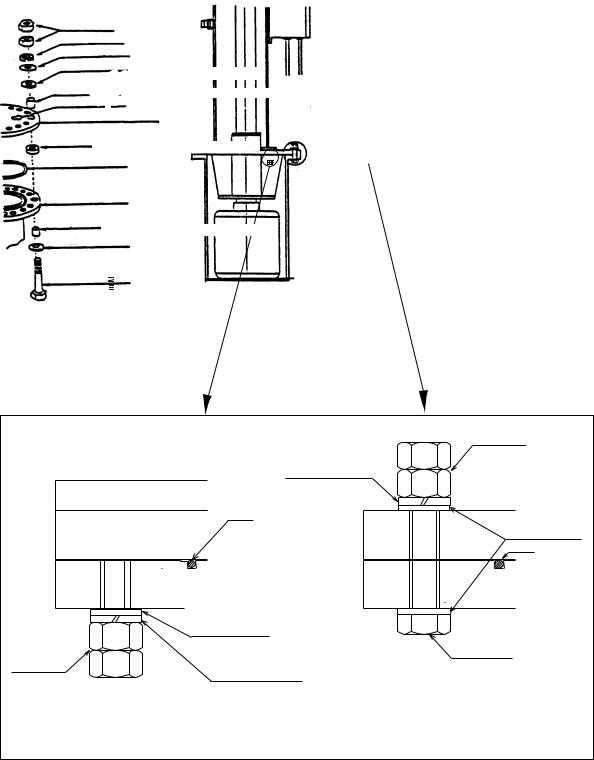
Hex. Bolt
Flat Washer
Hull Unit Flange |
||
O-ring |
|
|
Flat Washer |
|
|
Spring Washer |
||
Hex. |
Hex. Bolt |
|
Flat Washer (M20) |
||
Nut |
||
|
||
Attachment Flange
O-ring
Existing Tank
Flat Washer
Spring Washer
Hex. Nut
Attachment flange for 1200 mm stroke transducer, sectional view
1-16
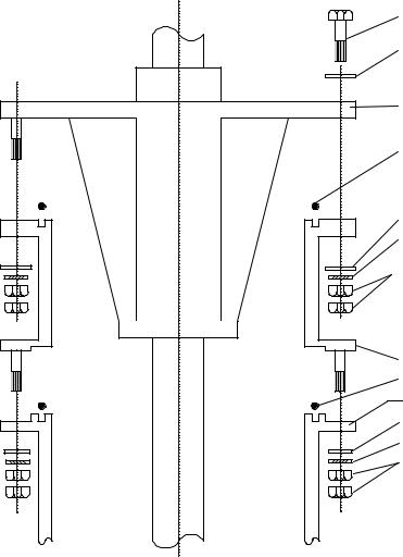
Hex. Bolt
Flat Washer
Hull Unit Flange |
O-ring |
Flat Washer |
Spring Washer |
Hex. Nut |
Attachment Flange
O-ring
Existing Tank
Flat Washer
Spring Washer
Hex. Nut
*: FSV-244E only
Attachment flange for 1600 mm stroke transducer, sectional view
1-17
1.7Mounting the Cable for Extension Kit (option)
For extension of the transducer cable between the hull unit and the transceiver unit, use the extension cable kit (option). The kit is available in 5 and 15 meter lengths.
Name: Cable for Extension Kit, Type: FSV-2451, Code No.: 000-067-030
Name |
Type |
Code No. |
Qty |
Remarks |
Junction box |
FSV-245 |
000-067-032 |
1 |
|
Cable assembly |
10S2138*5m* |
000-145-350 |
1 |
|
10S2139*5m* |
000-145-354 |
1 |
|
|
|
10S2144*12.9m* |
000-145-360 |
1 |
|
Name: Cable for Extension Kit, Type: FSV-2452, Code No.: 000-067-031
Name |
Type |
Code No. |
Qty |
Remarks |
Junction box |
FSV-245 |
000-067-032 |
1 |
|
Cable |
10S2138*15m* |
000-145-351 |
1 |
|
10S2139*15m* |
000-145-355 |
1 |
|
|
assembly |
|
|||
10S2144*22.9m* |
000-145-361 |
1 |
|
|
|
|
Fasten the Junction Box to bulkhead with 4 bolts (M8, local supply).
Junction box
1-18
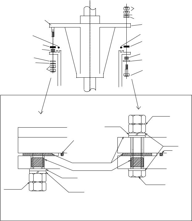
1.8Attachment Kit (option)
When using the retraction tank of FSV-243E/244E for FSV-247/248, the optional attachment kit OP10-24 is necessary.
Name: Attachment kit |
Type: OP10-24 |
Code no.: 006-943-530 |
|
|
Name |
Type |
|
Code No. |
Qty |
Insulation gasket |
MS-1000-67 |
|
000-857-220 |
24 |
Insulation gasket (2) |
MS-1000-68 |
|
000-857-221 |
24 |
1.Clean the hull unit flange, the O-ring and O-ring groove. Coat them with a slight amount of grease. Place the O-ring in position on the tank flange.
2.Lay the insulation gasket (1) on the top of the tank flange.
3.Orient the hull unit so that the bow mark (inscribed) on its flange points toward the ship’s bow. Note that heading adjustment in the display unit is required if the bow mark does not face the ship’s bow.
4.Confirm that the O-ring and the insulation gasket (1) are in position.
5.Place the hull unit on the tank.
6.Seven of the 24 bolt holes on the hull unit flange have already been fitted with bolts (stern side). Insert the insulator gasket (2) into the bolt holes of the tank flange to which these seven bolts are fitted.
7.Coat every bolt, washer and nut with a slight amount of grease to ease removal. Fit the insulation gasket (2) into the bolt holes of the tank flange. Fasten the hull unit to the retraction tank with insulation gasket (2), flat washers, spring washers and hex bolts.
8.Reinforce the hull unit against vibration by extending stays to the ship’s hull from the two eye bolts at the top of the hull unit, referring to the figure at the top of page 1-7.
1-19
|
Hex. nut |
|
Spring washer |
Flange of the hull unit |
Flat washer |
|
Flange of the hull unit |
|
O-ring |
O-ring |
|
|
||
Insulation gasket (1) |
Insulation gasket (1) |
|
|
||
Insulation gasket (2) |
|
|
|
Insulation gasket (2) |
|
Flat washer |
Flat washer |
|
Spring washer |
||
|
||
Hex. nut |
Hex. bolt |
|
|
Hex. bolt
Spring washer
O-ring
Flat washer
O-ring
Insulation gasket
Retraction tank
Insulation gasket (2)
Flat washer
Hex. bolt
Hex. nut
Spring washer
Stern side |
Bow side |
(Seven locations) |
(17 locations) |
Using the optional attachment kit
1-20

2.WIRING
2.1How to Use the Crimping Tool, Pin Extractor
A special crimping tool is necessary for connection of wires to the contact pins of the 38P connector. The pin extractor removes the contact pin from the connector body. This paragraph describes how to crimp and extract the contact pin.
Crimping Tool |
Contact Pin |
Pin Extractor |
06-1001-016 |
60-8017-0313-00-339 |
06-1877-04 |
|
(000-519-542) |
(000-519-595) |
Crimping tool, contact pin, pin extractor
2.1.1How to use the crimping tool
1.Strip the vinyl sheath of the wire to expose the core by 3 mm to 4 mm.
2.Hold the crimping tool horizontally and insert the contact pin with its slit facing downward into the crimp hole on the crimping tool.
3.Insert the wire onto the contact pin and squeeze the handle until the rachet releases. (The wire should be placed deep enough into the contact pin so that its end comes in contact with the stopper plate of the crimping tool.) With crimping completed, pull the wire while holding the contact pin to make sure that it is tightly fastened.
2.1.2How to use the pin extractor
If a contact pin is inserted into an incorrect hole on the connector body, remove it with
the pin extractor. 2
1
1. Push the pin extractor into the pin hole from the side opposite to the pin inserting side.
2. Push in the head of the pin extractor. The retaining spring comes free and the contact pin can be removed.
2-1

2.2Location of Connectors
MONITOR UNIT 10S2076 (5/10 m) |
|
|
|
FSV-2400 |
|
|
|
|
|
10S2076 (5/10 m) |
|
CONTROL UNIT FSV-2401 |
|
||
10S2074 (10 m) or 10S2075 (30 m) |
CONTROL UNIT FSV-2401 |
||
|
|
|
|
Transceiver |
|
|
Monitor |
|
|
(Local supply) |
|
unit |
|
|
|
Monitor unit |
|
|
|
Control unit |
|
|
Monitor cable |
|
|
|
|
Monitor unit |
|
|
(Local supply) |
|
|
|
|
Control unit |
|
|
|
External |
|
|
|
monitor |
|
|
*2: If connector may loosen by |
|
(option) |
|
|
|
*2 |
vibration the monitor may also |
|
|
|
||
Processor unit clamp |
|
be connected inside. |
|
10S1258 |
|
||
TRANSCEIVER UNIT |
DPYCY-1.5 *3 |
FSV-2402/2402S |
|
FSV-241E |
|
|
PROCESSOR UNIT |
|
|
|
|
|
|
100/110/115/ |
|
|
|
220/230 VAC |
|
|
|
1φ , 50/60 Hz |
|
POWER SUPLY UNIT |
||
FSV-242 |
||
*4 |
|
|
*3 |
100/110/115/ |
|
4 |
||
220/230 VAC |
||
DPYCY- |
||
1φ , 50/60 Hz |
||
|
||
DPYCY-4 *3
10S2078 (8 m) *4 
 *5 *6
*5 *6 
220 VAC
3φ , 50/60 Hz
TPYCY-4 *3 |
HULL UNIT
FSV-243E (1200 mm stroke)/
FSV-244E (1600 mm stroke)
10S2140 (15 m), 10S2141 (14.5 m)
*5 *6
*3: Japan Industrial Standard cable
*4: The same type of connector is fitted at each end, however the connector where the amount of sheath removed is greater should be connected to the transceiver unit.
*5: When running the cables of 10S2078, 10S2140 and 10S2141, refer to next page.
*6: When using cable for extension kit, the length of the cable between the transceiver unit and the hull unit is 10 m or 20 m.
Interconnection
2-2
Loading...