


SSB RADIOTELEPHONE
FS-1570 (150 W) 

 FS-2570 (250 W)

9-52 Ashihara-cho,
Nishinomiya 662-8580, JAPAN
Telephone : 0798-65-2111
Fax |
: 0798-65-4200 |
All rights reserved. |
Printed in Japan |
Pub. No. OME-56360
( YOSH ) FS-1570/2570
The paper used in this manual is elemental chlorine free.
FURUNO Authorized Distributor/Dealer
FIRST EDITION :OCT. 2002
E3 : FEB. 14, 2006
*00080933802*
*00080933802*
* 0 0 0 8 0 9 3 3 8 0 2 *
*OME56360E30*
*OME56360E30*
* O M E 5 6 3 6 0 E 3 0 *
Distress Alert Calling Procedure
Below is the procedure for transmitting a distress alert via radiotelephone. Transmit the distress alert when a life-endangering situation occurs on your vessel.
1.Open the DISTRESS button cover and press the [DISTRESS] button more than three seconds to show the following display, then release the [DISTRESS] button.
Distress
call in progress!
NATURE: UNDESIGNATED
POS: 12˚34N 123˚45E AT 12:34
TELEPHONE |
2182.0 KHZ |
DSC FREQ : |
2187.5 KHZ |
TIME TO GO : |
30S |
2. After the distress call has been transmitted, the following displays appear in order.
Wait for distress acknowledgement.
NATURE: UNDESIGNATED
POS:12˚34N 123˚45E AT 12:34
TELEPHONE |
2182.0 KHZ |
DSC FREQ : |
2187.5 KHZ |
|
|
TIME TO GO: |
2M10S |
When distress call is acknowledged by coast station (usually within
1 min to 2 min 45 seconds)
Distress acknowledge call received.
FROM COAST: 001234567 SHIP IN DIST: 123456789 NATURE: UNDESIGNATED POS: 12˚34N 123˚45E AT 12:34
TELEPHONE |
2182.0 KHZ |
|
|
|
|
|
STOP ALARM |
|
3.The audio alarm sounds; press the [CANCEL] key to silence the alarm.
4.Communicate with the coast station via radiotelephone as below. (In the dual control unit system, communication can be done from any control unit, after the distress alert has been transmitted. To restore priority to the #1 control unit after completion of distress communications, turn it off and on again.)
a)Say MAYDAY three times.
b)Say “This is …” name of your vessel and your call sign three times.
c)Give nature of distress and assistance needed.
d)Give description of your vessel (type, number of persons onboard, etc.) and any other information which may aid in rescue.
i

 SAFETY INSTRUCTIONS
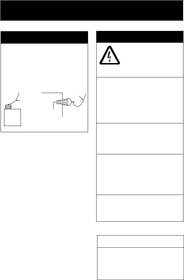
 DANGER
Never touch the SSB antenna, antenna coupler or lead-in insulator when the SSB radiotelephone is transmitting.
High voltage which will cause death or serious injury is present at the locations shown in the illustration below when the SSB radiotelephone is transmitting.
|
Antenna |
|
Indoor |
Wire |
|
Antenna Wire |
|
|
(High Voltage) |
|
|
|
Lead-in |
|
Antenna |
Insulator |
|
(High |
||
Coupler |
||
Voltage) |
||
|
 WARNING
ELECTRICAL SHOCK HAZARD
Do not open the equipment.
Only qualified personnel should work inside the equipment.
Immediately turn off the power at the switchboard if water leaks into the equipment or something is dropped in the equipment.
Continued use of the equipment can cause fire or electrical shock. Contact a FURUNO agent for service.
Do not disassemble or modify the equipment.
Fire, electrical shock or serious injury can result.
Immediately turn off the power at the switchboard if the equipment is emitting smoke or fire.
Continued use of the equipment can cause fire or electrical shock. Contact a FURUNO agent for service.
Do not operate the equipment with wet hands.
Electrical shock can result.
 CAUTION
Use the proper fuse.
Use of the wrong fuse can cause serious damage to the equipment and void the warranty.
ii
 CAUTION
Do not operate the [DISTRESS] button except in case of a life-endangering situation on your vessel.
If the distress alert is accidentally transmitted, contact the nearest coast station and inform them of the accidental transmission as follows:
a)Ship's name
b)Ship's call sign and DSC number
c)Position at time of transmission
d)Time of transmission
This equipment is intended for maritime use. Do not use it in other applications.
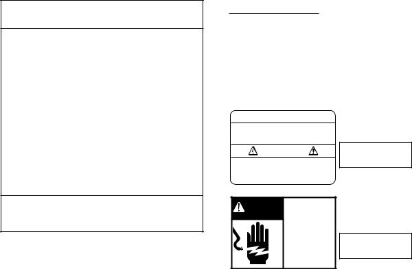
WARNING LABEL
A warning label is attached to the transceiver unit and a danger label is attached to the antenna coupler.
Do not remove the labels.
If a label is missing or illegible, contact a FURUNO agent or dealer about replacement.
 WARNING
To avoid electrical shock, do not remove cover. No user-serviceable parts inside.
DANGER Hazardous voltage. Can shock, burn, or cause death.
Do not touch antenna wire, insulator and terminal.
Name: Warning Label (1)
Type: 86-003-1011-1
Code No.: 100-236-231
TRANSCEIVER UNIT
Name: Danger Label
Type: 05-062-0213-0
Code No.: 100-199-230
ANTENNA
COUPLER
iii
TABLE OF CONTENTS
|
|
|
|
|
........................................................................................................FOREWORD |
ix |
|||
SYSTEM CONFIGURATION................................................................................ |
xi |
|||
SPECIFICATIONS........................................................................................... |
SP-1 |
|||
1 |
OPERATIONAL OVERVIEW......................................................................... |
1-1 |
||
|
1.1 |
Controls....................................................................................................................... |
1-1 |
|
|
1.2 |
Turning the Power On/Off ............................................................................................ |
1-2 |
|
|
1.3 |
Panel Dimmer, LCD Contrast....................................................................................... |
1-2 |
|
|
1.4 |
Indications ................................................................................................................... |
1-3 |
|
|
|
1.4.1 DSC standby screen......................................................................................... |
1-3 |
|
|
|
1.4.2 Radiotelephone screen..................................................................................... |
1-3 |
|
|
1.5 |
Loudspeaker................................................................................................................ |
1-4 |
|
|
1.6 |
Scanning Routine DSC Frequencies ........................................................................... |
1-4 |
|
|
1.7 Automatic Acknowledge On/Off.................................................................................... |
1-5 |
||
|
1.8 |
Manual Entry of Position and Time .............................................................................. |
1-5 |
|
|
1.9 |
System Characteristics................................................................................................ |
1-7 |
|
|
|
1.9.1 Equipment priority............................................................................................. |
1-7 |
|
|
|
1.9.2 Controls become inoperative ............................................................................ |
1-7 |
|
|
|
1.9.3 Controls become operative............................................................................... |
1-7 |
|
|
|
1.9.4 Automatic setting of working frequency............................................................. |
1-7 |
|
|
1.10 Power Supply Unit (option) ........................................................................................ |
1-8 |
||
2 |
SSB RADIOTELEPHONE ............................................................................. |
2-1 |
||
|
2.1 |
Transmitting................................................................................................................. |
2-1 |
|
|
|
2.1.1 Choosing class of emission .............................................................................. |
2-1 |
|
|
|
2.1.2 Choosing channel, frequency ........................................................................... |
2-2 |
|
|
|
2.1.3 Tuning .............................................................................................................. |
2-3 |
|
|
|
2.1.4 Using the handset............................................................................................. |
2-4 |
|
|
|
2.1.5 Monitoring transceiver output power................................................................. |
2-4 |
|
|
|
2.1.6 Reducing transmitter power.............................................................................. |
2-5 |
|
|
|
2.1.7 Displaying IA, IC, VC or RF .............................................................................. |
2-5 |
|
|
2.2 |
Receiving..................................................................................................................... |
2-6 |
|
|
|
2.2.1 RF gain (sensitivity) adjustment........................................................................ |
2-6 |
|
|
|
2.2.2 S-meter ............................................................................................................ |
2-6 |
|
|
|
2.2.3 Monitoring traffic on intended transmit frequency.............................................. |
2-6 |
|
|
|
2.2.4 Receiving AM broadcasting stations ................................................................. |
2-6 |
|
|
|
2.2.5 Squelch control, squelch frequency .................................................................. |
2-7 |
|
|
|
2.2.6 Noise blanker ................................................................................................... |
2-7 |
|
|
2.3 |
Intercom ...................................................................................................................... |
2-8 |
|
|
2.4 |
Telex Communications................................................................................................. |
2-8 |
|
|
2.5 When Automatic Tuning Fails ...................................................................................... |
2-9 |
||
iv
|
2.6 |
User Channels ........................................................................................................... |
2-10 |
|
|
2.6.1 Registering user channels............................................................................... |
2-10 |
|
|
2.6.2 Deleting user channels.................................................................................... |
2-12 |
|
2.7 |
FAX Enable/Disable ................................................................................................... |
2-12 |
|
2.8 |
Speaker Setting in Off Hook ....................................................................................... |
2-13 |
3 |
DSC OVERVIEW ........................................................................................... |
3-1 |
|
|
3.1 What is DSC? .............................................................................................................. |
3-1 |
|
|
3.2 |
DSC Call ...................................................................................................................... |
3-1 |
|
|
3.2.1 Distress alert call and reply ............................................................................... |
3-3 |
|
|
3.2.2 Individual call .................................................................................................... |
3-4 |
|
3.3 Audio Alarms................................................................................................................ |
3-4 |
|
|
3.4 |
Interpreting Call Displays ............................................................................................. |
3-5 |
|
|
3.4.1 Receive calls..................................................................................................... |
3-5 |
|
|
3.4.2 Send calls ......................................................................................................... |
3-7 |
4 |
DISTRESS OPERATIONS ............................................................................ |
4-1 |
|
|
4.1 |
Sending Distress Alert.................................................................................................. |
4-1 |
|
|
4.1.1 Sending distress alert by DISTRESS button, nature of distress not specified.... |
4-1 |
|
|
4.1.2 Sending distress alert by DISTRESS button, nature of distress specified.......... |
4-3 |
|
4.2 |
Receiving a Distress Alert ............................................................................................ |
4-6 |
|
|
4.2.1 Distress alert received on MF band................................................................... |
4-7 |
|
|
4.2.2 Distress alert received on HF band ................................................................... |
4-9 |
|
4.3 |
Sending Distress Relay on Behalf of a Ship in Distress.............................................. |
4-13 |
|
|
4.3.1 Sending distress relay to coast station ............................................................ |
4-13 |
|
|
4.3.2 Sending distress relay to all ships ................................................................... |
4-16 |
|
4.4 |
Receiving Distress Relay All Ships............................................................................. |
4-19 |
|
4.5 |
Receiving Distress Relay from Coast Station ............................................................. |
4-19 |
5 |
CALLING, RECEIVING.................................................................................. |
5-1 |
|
|
5.1 All Ships Call................................................................................................................ |
5-1 |
|
|
|
5.1.1 Sending an all ships call.................................................................................... |
5-1 |
|
|
5.1.2 Receiving an all ships call ................................................................................. |
5-3 |
|
5.2 |
Individual Call............................................................................................................... |
5-4 |
|
|
5.2.1 Sending an individual call.................................................................................. |
5-4 |
|
|
5.2.2 Receiving an individual call ............................................................................. |
5-10 |
|
5.3 |
Group Call.................................................................................................................. |
5-15 |
|
|
5.3.1 Sending a group call ....................................................................................... |
5-15 |
|
|
5.3.2 Receiving a group call..................................................................................... |
5-18 |
|
5.4 |
Geographical Area Call .............................................................................................. |
5-19 |
|
|
5.4.1 Sending a geographical area call .................................................................... |
5-19 |
|
|
5.4.2 Receiving a geographical area call.................................................................. |
5-22 |
|
5.5 |
Neutral Craft Call........................................................................................................ |
5-23 |
|
|
5.5.1 Sending a neutral craft call.............................................................................. |
5-23 |
|
|
5.5.2 Receiving a neutral craft call ........................................................................... |
5-25 |
|
5.6 |
Medical Transport Call ............................................................................................... |
5-26 |
|
|
5.6.1 Sending a medical transport call ..................................................................... |
5-26 |
|
|
5.6.2 Receiving a medical transport call................................................................... |
5-27 |
v
|
5.7 |
Polling Call ................................................................................................................ |
5-28 |
|
|
5.7.1 Sending a polling call...................................................................................... |
5-28 |
|
|
5.7.2 Receiving a polling call ................................................................................... |
5-31 |
|
5.8 |
Position Call .............................................................................................................. |
5-33 |
|
|
5.8.1 Position call: requesting other ship’s position.................................................. |
5-34 |
|
|
5.8.2 Position call: other ship requests your position ............................................... |
5-36 |
|
5.9 |
PSTN Call.................................................................................................................. |
5-38 |
|
|
5.9.1 Sending a PSTN call, receiving acknowledge back (ACK BQ) ........................... |
5-38 |
|
|
5.9.2 Receiving a PSTN call, sending acknowledge back (ACK BQ)....................... |
5-42 |
|
|
5.9.3 PSTN call disconnection, receiving charge information |
|
|
|
(ship disconnects line) .................................................................................. |
5-43 |
|
|
5.9.4 PSTN call disconnection, receiving charge information (coast station |
|
|
|
disconnects line)........................................................................................... |
5-44 |
|
5.10 Log File.................................................................................................................... |
5-45 |
|
|
|
5.10.1 Opening a log file.......................................................................................... |
5-45 |
|
5.11 Erasing Message Files............................................................................................. |
5-46 |
|
6 |
PREPARING TX CALLS ............................................................................... |
6-1 |
|
|
6.1 |
Preparing Individual Calls ............................................................................................ |
6-1 |
|
6.2 |
Preparing Group Calls ................................................................................................. |
6-4 |
|
6.3 |
Preparing Geographical Area Calls.............................................................................. |
6-5 |
|
6.4 |
Preparing PSTN Calls.................................................................................................. |
6-7 |
|
6.5 |
Preparing Test Calls..................................................................................................... |
6-8 |
|
6.6 |
Sending Prepared Calls............................................................................................... |
6-9 |
|
6.7 |
Deleting Send Message Files .................................................................................... |
6-10 |
|
6.8 |
Printing List of Send Message Files........................................................................... |
6-10 |
7 |
DSC/WATCH RECEIVER SETUP ................................................................. |
7-1 |
|
|
7.1 |
Setting Alarms ............................................................................................................. |
7-1 |
|
7.2 Auto Ack Menu............................................................................................................. |
7-2 |
|
|
7.3 |
Printing Messages ....................................................................................................... |
7-3 |
|
7.4 |
Setting Scan Frequencies............................................................................................ |
7-4 |
|
|
7.4.1 Distress frequencies......................................................................................... |
7-4 |
|
|
7.4.2 Routine frequencies.......................................................................................... |
7-4 |
|
7.5 Adjusting Volume......................................................................................................... |
7-6 |
|
8 |
NBDP SYSTEM OVERVIEW......................................................................... |
8-1 |
|
|
8.1 |
Turning on the NBDP System ...................................................................................... |
8-1 |
|
8.2 |
Description of Equipment............................................................................................. |
8-2 |
|
|
8.2.1 Terminal unit..................................................................................................... |
8-2 |
|
|
8.2.2 Keyboard.......................................................................................................... |
8-3 |
|
8.3 |
Function Keys, Menu Operation .................................................................................. |
8-4 |
|
|
8.3.1 Menu conventions ............................................................................................ |
8-4 |
|
|
8.3.2 Menu overview ................................................................................................. |
8-5 |
|
|
8.3.3 Function key description................................................................................... |
8-6 |
vi
9 NBDP PREPARATIONS................................................................................ |
9-1 |
|
9.1 |
Registering Answerback Code & ID Codes .................................................................. |
9-1 |
|
9.1.1 Registering answerback code ........................................................................... |
9-1 |
|
9.1.2 Registering ID codes......................................................................................... |
9-2 |
9.2 |
Station List ................................................................................................................... |
9-2 |
|
9.2.1 Registering stations........................................................................................... |
9-3 |
|
9.2.2 Editing/Deleting stations.................................................................................... |
9-4 |
9.3 |
Timer Programming...................................................................................................... |
9-5 |
|
9.3.1 Registering timer programs............................................................................... |
9-5 |
|
9.3.2 Editing/Deleting timer programs ........................................................................ |
9-6 |
9.4 |
User Channels ............................................................................................................. |
9-6 |
|
9.4.1 Registering user channels................................................................................. |
9-6 |
|
9.4.2 Editing/Deleting user channels.......................................................................... |
9-7 |
9.5 |
Scan Channel Groups.................................................................................................. |
9-7 |
|
9.5.1 Registering scan channel groups ...................................................................... |
9-7 |
|
9.5.2 Editing/Deleting scan channel groups ............................................................... |
9-8 |
10 NBDP FILE OPERATIONS.......................................................................... |
10-1 |
|
10.1 |
Opening and Closing Files ....................................................................................... |
10-1 |
10.2 |
Creating Files........................................................................................................... |
10-1 |
10.3 |
Saving a File ............................................................................................................ |
10-3 |
|
10.3.1 Formatting floppy disks ................................................................................. |
10-3 |
|
10.3.2 Saving a file .................................................................................................. |
10-4 |
10.4 |
Editing Files ............................................................................................................. |
10-5 |
|
10.4.1 Cutting and pasting text ................................................................................ |
10-5 |
|
10.4.2 Copying and pasting text............................................................................... |
10-6 |
|
10.4.3 Select all ....................................................................................................... |
10-6 |
|
10.4.4 Searching text............................................................................................... |
10-6 |
|
10.4.5 Replacing text ............................................................................................... |
10-7 |
|
10.4.6 Goto line ....................................................................................................... |
10-7 |
|
10.4.7 Goto top, Goto bottom................................................................................... |
10-8 |
10.5 |
Opening Files........................................................................................................... |
10-8 |
|
10.5.1 Opening a file................................................................................................ |
10-8 |
|
10.5.2 Switching between files................................................................................. |
10-8 |
10.6 |
Renaming Files ........................................................................................................ |
10-9 |
10.7 Saving a File Under a New Name ............................................................................ |
10-9 |
|
10.8 |
Deleting Files ........................................................................................................... |
10-9 |
10.9 |
Real Time Printing.................................................................................................... |
10-9 |
10.10 Printing Files ........................................................................................................ |
10-10 |
|
11 NBDP TRANSMITTING, RECEIVING ......................................................... |
11-1 |
|
11.1 |
Manual Calling ......................................................................................................... |
11-1 |
11.2 ARQ Mode Operation ............................................................................................... |
11-3 |
|
11.3 |
FEC Mode Operation................................................................................................ |
11-5 |
11.4 |
Choosing Receive Mode .......................................................................................... |
11-5 |
11.5 |
Communication Example.......................................................................................... |
11-6 |
vii
11.6 |
Timer Operation ........................................................................................................ |
11-8 |
|
11.6.1 Enabling timer operation ................................................................................ |
11-8 |
|
11.6.2 Stopping timer operation................................................................................ |
11-9 |
11.7 |
Scanning................................................................................................................... |
11-9 |
11.8 Communication Buffer............................................................................................. |
11-10 |
|
11.9 |
Preparing Macrofiles for Automatic Telex ................................................................ |
11-10 |
|
11.9.1 Automatic telex overview ............................................................................. |
11-10 |
|
11.9.2 Preparations ................................................................................................ |
11-11 |
|
11.9.3 Commands .................................................................................................. |
11-12 |
|
11.9.4 Store-and-forward method ........................................................................... |
11-13 |
|
DIRTLX macrofile................................................................................................... |
11-15 |
11.10 Automatic Telex using Macrofile ............................................................................ |
11-17 |
|
12 MAINTENANCE & TROUBLESHOOTING |
................................................. 12-1 |
|
12.1 |
Daily Test................................................................................................................. |
12-1 |
12.2 |
Radiotelephone Test................................................................................................ |
12-2 |
12.3 Antenna Coupler Test .............................................................................................. |
12-2 |
|
12.4 |
Maintenance............................................................................................................ |
12-3 |
12.5 |
Replacement of Fuses............................................................................................. |
12-4 |
12.6 |
Simple Troubleshooting ........................................................................................... |
12-5 |
12.7 |
Error Messages ....................................................................................................... |
12-5 |
12.8 |
Test Call................................................................................................................... |
12-7 |
12.9 |
NBDP Terminal Unit Maintenance............................................................................ |
12-9 |
|
12.9.1 Cleaning the equipment................................................................................ |
12-9 |
|
12.9.2 Connectors and earth connection ................................................................. |
12-9 |
|
12.9.3 Floppy disk drive........................................................................................... |
12-9 |
|
12.9.4 Diagnostics.................................................................................................. |
12-10 |
APPENDIX ...................................................................................................... |
AP-1 |
Menu Tree ....................................................................................................................... |
AP-1 |
Frequency Tables ............................................................................................................ |
AP-4 |
Telex Abbreviations........................................................................................................ |
AP-17 |
Digital Interface (IEC 61162-1)....................................................................................... |
AP-18 |
Parts List ....................................................................................................................... |
AP-23 |
Parts Location ............................................................................................................... |
AP-26 |
INDEX............................................................................................................... |
IN-1 |
Declaration of conformity |
|
viii
FOREWORD
Thank you for purchasing the FS-1570 (150 W)/FS-2570 (250 W) SSB Radiotelephone. We are confident you will discover why FURUNO has become synonymous with quality and reliability.
Dedicated in the design and manufacture of marine electronics equipment for over half a century, FURUNO Electric Company has gained an unrivaled reputation as a world leader in the industry. This is the result of our technical excellence as well as our worldwide distribution and service network.
Please carefully read and follow the safety information and operating and maintenance instructions set forth in this manual before attempting to operate the equipment and conduct any maintenance. Your unit will perform to the utmost of its ability only if it is operated and maintained in accordance with the correct procedures.
Note: The example screens shown in this manual may not match the screens you see on your display. The screen you see depends on your system configuration and equipment settings.
Features
The FS-1570/FS-2570 is an MF/HF SSB Radiotelephone with a built-in DSC/Watch Receiver, all contained in a surprisingly compact cabinet. An NBDP (Narrow Band Direct Printing) Terminal Unit is optionally available.
Data is displayed on a large, easy-to-read backlit LCD. Operation is simplified by the use of few keys and easy-to-follow menus.
The built-in DSC/watch receiver produces and receives digital selective calls for quick and efficient establishment of distress, urgency, safety and routine communications with other ships and coast stations that install any MF/HF DSC facilities.
The main features are
General
•Fully meets the following regulations: IMO A.694(17), IMO A.804(19), IMO A.806(19), IMO A.813(19), IMO MSC 68(68), IEC 60945, IEC 61907-3/8/9, IEC-61162-1, EIV-300/338, ITU-R M.493-10, M.541-8, M.1082-1, EN 300 373, EN 300 338, EN 300 033 and ETS 300 067.
•One-touch testing facility
•Automatic entry of position with manual override
•Optional printer can automatically print out DSC and NBDP received messages and test results.
ix
DSC/watch receiver
•Distress, safety and routine calling
•Scanning of DSC frequencies for distress and general calls on MF/HF
•File editing capability for readiness in case of emergency
•PSTN (Public Switched Telephone Network) capability standard
•Log stores 50 each of latest ordinary, distress and transmitted messages, in separate memory blocks.
NBDP (with optional NBDP Terminal Unit IB-581/IB-583)
•Automatic error-free telex communications and distress message in compliance with GMDSS requirements
•LCD monitor and keyboard comply with ITU regulations
•Pop-up menus for user-friendly operation
•Memory for 100 operator-customized channels
•Real time message printing with Printer PP-510
Program Number
PC Board |
Program No. |
On Display |
Remarks |
MAIN (Transceiver Unit) |
0550205101 |
Ver. 01 |
FS-1570T/FS-2570T |
PANEL 1 (#1 Control Unit) |
0550206101 |
Ver. 01 |
FS-2570C |
PANEL 2 (#2 Control Unit) |
0550206101 |
Ver. 01 |
Optional unit |
MODEM (DSC) |
0550207101 |
Ver. 01 |
|
NBDP MODEM |
0550208101 |
Ver. 01 |
Optional pcb |
Terminal Unit IB-581 (optional unit)
PC Board |
Program No. |
On Display |
Remarks |
Terminal Unit |
0550210122 |
Ver. 1.22 |
|
Terminal Unit IB-583 (optional unit)
PC Board |
Program No. |
On Display |
Remarks |
Terminal Unit |
0550209122 |
Ver. 1.22 |
|
x

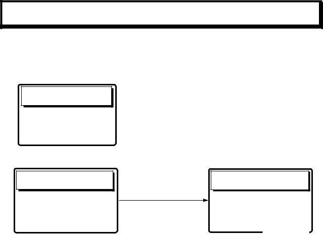
SYSTEM CONFIGURATION
FS-2570 (250 W)
|
* |
** |
|
|
|
# = 2.6 m |
# |
# |
|
|
|
|
|
|
|
|
|
PREAMP |
|
PREAMP |
|
Antenna Coupler |
|
whip |
|
|
|||
FAX-5 |
|
FAX-5 |
|
AT-1560-25 |
|
antenna |
|
|
|||
NAVIGATOR |
RX BOARD** |
|
|
|
CONTROLLER 1 |
INCOMING
INDICATOR
IC-303-DSC
TRANSCEIVER
UNIT
FS-2570T
TELEX DISTRESS
ALERT BUTTON
IC-302-DSC or
DISTRESS MESSAGE
CONTROLLER CONTROLLER 2
DMC-5
LOUDSPEAKER
SEM-21Q
|
|
|
|
|
|
|
CONTROL UNIT |
|
HANDSET |
|
|
|
FS-2570C |
|
HS-2001 |
|
|
|
|
|
|
PRINTER |
|
|
|
|
|
PP-510 |
|
NBDP TERMINAL UNIT |
PRINTER |
||||
INTERFACE 24 VDC |
|||||
|
IB-581/IB-583 |
IF-8500* |
|||
* = Required for NBDP Terminal |
|
24 VDC |
and DSC to share printer. |
|
|
CONTROL UNIT |
|
FS-2570C |
|
*= For distress watch keeping receiver
**= For DSC general frequency
watch keeping receiver
AC/DC POWER |
POWER STATUS |
SUPPLY UNIT |
MONITOR |
PR-850A |
PSM-01 |
|
|
|
SHIP'S MAINS |
|||
|
24 VDC |
100-115/200-230 VAC |
||
|
|
1φ , 50/60 Hz |
||
Unit |
Category |
|
|
: STANDARD |
|
|
|||
Preamp Unit |
Exposed to weather |
|
|
: OPTION |
Antenna Coupler |
Exposed to weather |
|
|
: EXTERNAL EQUIPMENT |
Other Units |
Protected from weather |
|
|
|
|
|
|
||
xi

FS-1570 (150 W)
|
# |
|
|
2.6 m whip |
|
|
|
PREAMP |
|
Antenna Coupler |
|
antenna |
FAX-5 |
|
AT-1560-25 |
|
|
NAVIGATOR |
|
|
CONTROLLER 1 |
INCOMING |
|
INDICATOR |
|
IC-303-DSC |
|
|
TRANSCEIVER |
TELEX DISTRESS |
UNIT |
FS-1570T |
|
ALERT BUTTON |
|
IC-302-DSC |
|
or |
|
DISTRESS MESSAGE |
|
CONTROLLER |
|
DMC-5 |
CONTROLLER 2 |
|
|
|
|
LOUDSPEAKER
SEM-21Q
|
|
|
|
|
|
|
CONTROL UNIT |
|
HANDSET |
|
|
|
FS-2570C |
|
HS-2001 |
|
|
|
|
|
|
PRINTER |
|
|
|
|
|
PP-510 |
|
NBDP TERMINAL UNIT |
PRINTER |
||||
INTERFACE 24 VDC |
|||||
|
IB-581/IB-583 |
IF-8500* |
|||
* = Required for NBDP Terminal |
|
24 VDC |
and DSC to share printer. |
|
|
CONTROL UNIT |
|
FS-2570C |
|
# = For distress watch keeping receiver |
|
|
|
|
|
|
|
|
AC/DC POWER |
|
|
POWER STATUS |
|
|
|
SUPPLY UNIT |
|
|
||
|
|
|
|
MONITOR |
||
|
|
PR-300 |
|
|
||
|
|
|
|
PSM-01 |
||
|
|
|
|
|
||
|
|
|
|
|
||
|
|
|
|
|
|
|
SHIP'S MAINS |
|
|
||||
24 VDC 100-115/200-230 VAC |
|
|
||||
|
|
1φ , 50/60 Hz |
|
: STANDARD |
||
|
|
|
|
|
|
|
Unit |
Category |
: OPTION |
|
Preamp Unit |
Exposed to weather |
||
: EXTERNAL EQUIPMENT |
|||
Antenna Coupler |
Exposed to weather |
||
|
|||
Other Units |
Protected from weather |
|
xii
SPECIFICATIONS OF SSB RADIOTELEPHONE
FS-1570/2570
1 MF/HF DIGITAL RADIOTELEPHONE
1.1 GENERAL
1.1.1 |
Communication System |
Semi-duplex or simplex |
1.1.2 |
Class of Emission |
J3E: Telephone |
|
|
J2B (F1B): DSC or NBDP |
|
|
H3E: reception only |
1.1.3 |
Frequency Range |
100.00 kHz to 29,999.99 kHz |
1.1.4 |
Number of Channel |
User programmable: 255 TX/RX pairs |
|
|
All ITU channels incorporated (include DSC/NBDP channels) |
|
|
2182 kHz (single action) |
1.1.5 |
Display Method |
Monochrome LCD (120 x 64 dots) |
1.1.6 |
Backlight |
8 tones |
1.1.7 |
Contrast |
64 steps |
1.1.8 |
Warming up |
1 minute approx. (oven 20 minutes approx.) |
1.2 TRANSMITTER
1.2.1 |
Frequency Range |
1,606.5 kHz to 26.175 MHz (100 Hz steps) |
1.2.2 |
RF output Power |
FS-1570: 150 Wpep, FS-2570: 250 Wpep |
1.2.3 |
Frequency Resolution |
Within ±10 Hz |
1.2.4Modulation AF Response 350 Hz to 2.7 kHz
1.2.5 |
Modulation System |
Low power balanced modulation |
1.2.6 |
AF Input |
-46 dBm/600 ohms (Handset/Microphone) |
|
|
-10 dBm/600 ohms (Handset HS-2001) |
1.2.7 |
Line in |
0 dBm/600 ohms |
1.3 RECEIVER
1.3.1 |
Receiving System |
Double-conversion superheterodyne |
||||
1.3.2 |
Frequency Range |
100 kHz 29,999.9 kHz (10 Hz steps) |
||||
1.3.3 |
Sensitivity |
Input level at 10 ohms+250 pF (below 4 MHz) and 50 ohms |
||||
|
|
(above 4MHz) to produce SINAD 20 dB |
||||
|
|
|
Frequency Range |
|
J3E/H3E |
|
|
|
|
100 kHz to 300 kHz |
|
35 dBμV |
|
|
|
|
300 kHz to 1.6 MHz |
|
25 dBμV |
|
|
|
|
1.6 MHz to 4.0 MHz |
|
13 dBμV |
|
|
|
|
4.0 MHz to 30 MHz |
|
7 dBμV |
|
1.4 |
Intermediate Frequency |
1st: 72,455 kHz, 2nd: 455 kHz |
|
|
||
1.5 |
Selectivity |
J3E: 2.4kHz at -6dB, H3E: 6kHz at -6dB |
||||
|
|
J2B (F1B): 300Hz at -6dB |
|
|
||
1.6 |
Inter-modulation |
Better than 80 dBμV |
|
|
||
1.7 |
Spurious Response |
Better than 70 dB |
|
|
||
1.8 |
AGC |
SLOW/FAST/OFF |
|
|
||
1.9 |
BFO Frequency |
Telex/DSC: 1,700 Hz, Facsimile: 1,900 Hz |
||||
|
|
|
SP - 1 |
|
E5637S01E-M |
|
1.10 |
Audio Output Power |
Internal speaker: 1W/ 8 ohms |
|
|
External speaker: 4W/ 4 ohms |
|
|
Handset: 2.5mW/ 150 ohms |
|
|
Line output: 0 dBm/ 600 ohms |
1.11 |
Standard Features |
Noise Blanker, Voice-activated squelch, Pre-selector |
2 DSC/WATCH KEEPING RECEIVER
2.1DIGITAL SELECTIVE CALLING
2.1.1 |
Frequency Shift |
Space: 1785.0 ± 0.5 Hz, Mark: 1615.0 ± 0.5 Hz |
2.1.2 |
Baud Rate |
100 bps ± 30 x 10-6 |
2.1.3 |
Protocol |
Complies with ITU-R Rec.493-10, 541-8, 1082-1 |
2.1.4 |
Modulation |
AFSK |
2.1.5 |
Distress Alarm |
3.5 s to 4.5 s self-repetition |
2.1.6 |
Distress Alarm Memory |
50 messages |
2.2DSC/WATCH RECEIVER
2.2.1Frequency Range
|
MF/HF specification |
2187.5/ 8414.5 and 4207.5/ 6312/12577/16804.5 kHz |
|
MF specification |
2187.5 kHz |
2.2.2 |
Class of Emission |
F1B, J2B |
2.2.3 |
Antenna Impedance |
50 ohms |
2.2.4 |
Local Oscillator |
1st: F+54,455 kHz, 2nd: 54,000 kHz, 3rd: 456.7 kHz |
2.2.5 |
Frequency Stability |
±10 Hz |
2.2.6 |
Intermediate Frequency |
1st: 54,455 kHz, 2nd: 455 kHz |
2.2.7 |
Selectivity |
-6 dB: 270 Hz to 300 Hz, |
|
|
-30 dB: within ± 380 Hz, |
|
|
-60 dB: within ± 550 Hz |
2.2.8 |
Receiving System |
Double-conversion superheterodyne |
2.2.9 |
Radiation |
within 2 nW |
2.2.10 |
RX Error Rate |
1 % or less at 1 μV input voltage |
2.2.11 |
Spurious Response |
31.6 mV non-modulated at 10μV input voltage, |
|
|
at error rate within 1% |
2.2.12 |
Scanning Reception |
max. 6 frequencies within 2 s (MF/HF) |
2.2.13 |
Diagnosis |
Transmit high frequency signal of DSC |
2.3GENERAL WATCH KEEPING RECEIVER (FS-2570 ONLY, OPTION)
2.3.1 |
Frequency Range |
1,606.5 kHz to 27.5 MHz |
|
2.3.2 |
Class of Emission |
J2B, F1B |
|
2.3.3 |
Antenna Impedance |
50 ohms |
|
2.3.4 |
Local Oscillator |
1st: F+54,455 kHz, 2nd: 54,000 kHz, 3rd: 456.7 kHz |
|
2.3.5 |
Frequency Stability |
within ±10 Hz |
|
2.3.6 |
Intermediate Frequency |
1st: 54,455 kHz, 2nd: 455 kHz |
|
2.3.7 |
Selectivity |
-6 dB: 270 Hz to 300 Hz, |
|
|
|
-30 dB: within ± 380 Hz, |
|
|
|
SP - 2 |
E5637S01E-M |
|
|
-60 dB: within ±550 Hz |
2.3.8 |
Receiving System |
Double-conversion superheterodyne |
2.3.9 |
Radiation |
within 2 nW |
2.3.10 |
RX Error Rate |
1 % or less at 1 μV input voltage |
2.3.11 |
Spurious Response |
31.6 mV non-modulated at 10μV input voltage, |
|
|
at error rate within 1% |
2.3.12 |
Scanning Reception |
max. 6 frequencies within 2 s (MF/HF) |
2.3.13 |
Diagnosis |
Transmit high frequency signal of DSC |
3 |
NBDP FUNCTION (OPTION) |
||
3.1 |
GENERAL |
|
|
3.1.1 |
Communication Mode |
ARQ, FEC, DIRC (FSK) |
|
3.1.2 |
Protocol |
ITU-R M625-3, M476-5, M490, M491-1, M492-6 |
|
|
|
ID code |
4, 5, 9 column |
|
|
Line cord |
4B/3Y (Intl.) |
|
|
Modulation |
AFSK |
|
|
Tone frequency |
1615/1785Hz ± 0.5 Hz (mark/space) |
|
|
Tracking range |
±80 Hz |
3.1.3 |
Applications |
|
|
|
|
Auto-reception |
Setting timer and frequency (max. 10 settings available) |
|
|
Frequency scanning |
10 group max., 20 station as each group |
|
|
User-channels |
100 channels max. |
4 TERMINAL UNIT
4.1IB-583
4.1.1 |
Display |
10.4” color TFT LCD, 640 x 480 dots |
4.1.2 |
CPU |
HD6417615 (15.5 MHz) |
4.1.3 |
Memory |
Flash ROM: 1 MB, S-RAM: 256 KB |
4.1.4 |
FD Drive |
1.44MB 3.5” |
4.1.5 |
Keyboard |
82 keys, IBM PS/2 |
4.1.6 |
Other functions |
Text editor, FD control, Printer, Remote control for Transceiver, |
|
|
Diagnosis |
4.2IB-581
4.2.1 |
Display |
9.5” monochrome LCD, 680 x 480 dots |
4.2.2 |
CPU |
ALI M6117 (33 MHz) |
4.2.3 |
Memory |
Flash ROM 2 MB, DRAM 2 MB |
4.2.4 |
FD Drive |
1.44MB 3.5” |
4.2.5 |
Keyboard |
82 keys, IBM PS/2 |
5 |
ANTENNA COUPLER |
|
|
5.1 |
Tuning System |
CPU controlled fully automatic tuning system |
|
5.2 |
Frequency Range |
1.6 MHz to 27.5Hz |
|
5.3 |
Input Impedance |
50 ohms |
|
5.4 |
Antenna |
7m to 30m wire or whip antenna |
|
|
|
SP - 3 |
E5637S01E-M |
5.5 |
Power Capability |
150 W (FS-1570), 250 W (FS-2570) |
5.6 |
VSWR |
1.5 max |
5.7 |
Tuning Speed |
Within 15 s |
5.8 |
Dummy Load |
FS-1570: 10 ohms + 250 pF/100W mounted in coupler |
|
|
FS-2570: 10 ohms + 250 pF/200W mounted in coupler |
6 |
INTERFACE |
|
6.1 |
Input data sentences |
IEC 61162-1 (NMEA 0183-3) |
|
Ship’s Position (L/L) |
GGA>RMC>GLL |
|
Time |
ZDA |
7 POWER SUPPLY
7.1Transceiver Unit/Control Unit
|
FS-1570 |
24 VDC: 0.8 A, max. 20 A (TX) |
|
|
FS-2570 |
24 VDC: 1.5 A, max. 35 A (TX) |
|
7.2 |
Terminal Unit |
IB-583: 24 VDC: 0.6 A |
|
|
|
IB-581: 24 VDC: 0.8 A |
|
7.3 |
Printer |
24 VDC: 1.5 A |
|
7.4 |
AC/DC Power Supply Unit (option) |
100/110/115/220/230VAC, 1 phase, 50/60 Hz |
|
8 |
ENVIRONMENTAL CONDITION |
|
8.1 |
Ambient Temperature |
-15°C to +55°C |
8.2 |
Relative Humidity |
93 or less at 40°C |
8.3 |
Water proofing |
Control Unit (Panel): IPX2 |
|
(IEC 60529) |
Transceiver Unit/ Terminal Unit: IPX0 |
|
|
Antenna Coupler: IPX5 |
8.4 |
Vibration |
IEC 60945 |
9 COATING COLOR
9.1Control Unit/ Terminal Unit Panel: N3.0, Cover: 2.5GY5/1.5
9.2 |
Transceiver Unit |
2.5GY5/1.5 |
9.3 |
Antenna Coupler |
N9.5 (white) |
SP - 4 |
E5637S01E-M |

1OPERATIONAL OVERVIEW
1.1 Controls
FURUNO
DISTRESS |
1 RT |
2 DSC |
3 TEST |
|
|
|
|
2182 |
ABC |
|
DEF |
|
|
ALARM |
4IntComGHI |
5 ACK/SQABC |
6SCANMNO |
PUSH TO ENTER |
||
|
|
|
|
|
|
|
CANCEL |
7PQRS |
8 PRINTTUV |
9 WXYZ |
|
|
|
CALL |
FILE |
LOG |
|
SETUP |
|
|
*CURSOR |
0TUNE |
# |
|
POWER |
|
|
|
|
|
|
|
OVEN |
|
|
|
|
|
|
|
|
|
|
ENTER knob |
|
|
Description of controls |
|
|
|
Control |
|
Function |
POWER switch |
Turns the power on/off. |
|
DISTRESS |
Press and hold down the button more than three seconds to transmit the |
|
button |
distress alert. |
|
CALL key |
Transmits calls. |
|
ENTER knob |
Radiotelephone: Rotate to change TX/RX channel, sensitivity, audio |
|
|
volume, etc.; push to register selection. |
|
|
DSC: Rotate to choose menu items; push to register selection. |
|
CANCEL key |
• |
Cancels wrong data. |
|
• |
Restores previous menu. |
|
• |
Silences audio alarm. |
|
• |
Cancels transmission, printing. |
|
• |
Erases error message. |
1/ RT/2182 key |
Switches to the radiotelephone screen. Press and hold down more than |
|
|
two seconds to get 2182.0 kHz/J3E automatically. |
|
2/DSC key |
Composes DSC TX message. |
|
3/TEST key |
Executes daily test. |
|
4/IntCom key |
Turns on/off the intercom with other Control Unit FS-2570C. |
|
5/ ACK/SQ key |
DSC: Switches automatic and manual acknowledge alternately. |
|
|
Radiotelephone: Turns squelch on and off. |
|
6/SCAN key |
• Displays DSC standby screen. |
|
|
• Starts/stops scanning of DSC routine frequencies, on the DSC standby |
|
|
|
screen. |
1-1
1 OPERATIONAL OVERVIEW
7/ |
|
|
|
key |
• Turns loudspeaker on/off. |
|
|
|
|||
|
|
|
|||
|
|
|
|
|
(Note that this key does not silence the distress or urgency alarm.) |
8/PRINT key |
Prints communications log files, current screen (except DSC standby |
||||
|
|
|
|
|
screen and radiotelephone screen) and test results. |
9/ |
|
|
|
key |
Adjusts panel dimmer and LCD contrast. |
|
|
|
|||
FILE/CURSOR |
• Opens the send message file list from the DSC standby screen, to send |
||||
key |
|
stored message. |
|||
|
|
|
|
|
• Shifts cursor. |
LOG/TUNE key |
• Tunes antenna in radiotelephone operation. |
||||
|
|
|
|
|
• Displays message logs, in DSC operation. |
#/SETUP key |
Opens the Setup menu. |
||||
ALARM lamp |
• Flashes in red for distress and urgency calls. |
||||
|
|
|
|
|
• Flashes in green (more rapidly) for business, safety and routine calls. |
OVEN lamp |
Lights (in green) when mains switchboard is on. |
||||
1.2 Turning the Power On/Off
Press the [POWER] switch at the right-hand side of the control unit to power the system. Press it again to turn the system off. In the dual control unit system, the control unit connected to the CONTROLLER 1 port on the transceiver unit has priority and it controls the power for both the No.1 and No. 2 control units. The power switch of the No. 2 control unit powers on/off the No. 2 control unit only.
Note: Turn on ship’s mains five minutes before turning on this equipment.
1.3 Panel Dimmer, LCD Contrast
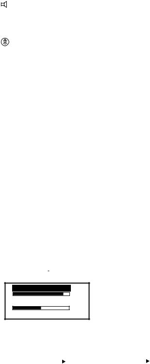
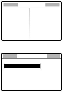
1. Press the [9/ ] key to show the dimmer/contrast adjustment window.
DIMMER (1~8)
6
CONTRAST (40~63)
45
EXIT:[ENT]
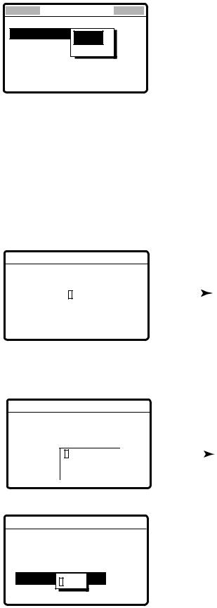
2.Rotate the [ENTER] knob to choose DIMMER or CONTRAST, whichever you want to adjust, and then push the [ENTER] knob.
|
|
DIMMER (1-8) |
|
|
|
|
CONTRAST (40-63) |
|
|
||||
|
|
|
|
6 |
|
|
|
|
|
|
55 |
|
|
|
|
|
|
|
|
|
|
|
|
|
|
||
|
|
|
|
|
|
|
|
|
|
|
|
||
|
|
|
|
|
|
|
|
|
|
|
|
|
|
|
|
|
|
|
|
|
|
|
|
|
|
|
|
Dimmer adjustment window |
Contrast adjustment window |
||||||||||||
3.Rotate the [ENTER] knob to adjust and then push the [ENTER] knob.
4.To quit, rotate the [ENTER] knob to choose “EXIT: [ENT]” and then push the [ENTER] knob.
1-2
1 OPERATIONAL OVERVIEW
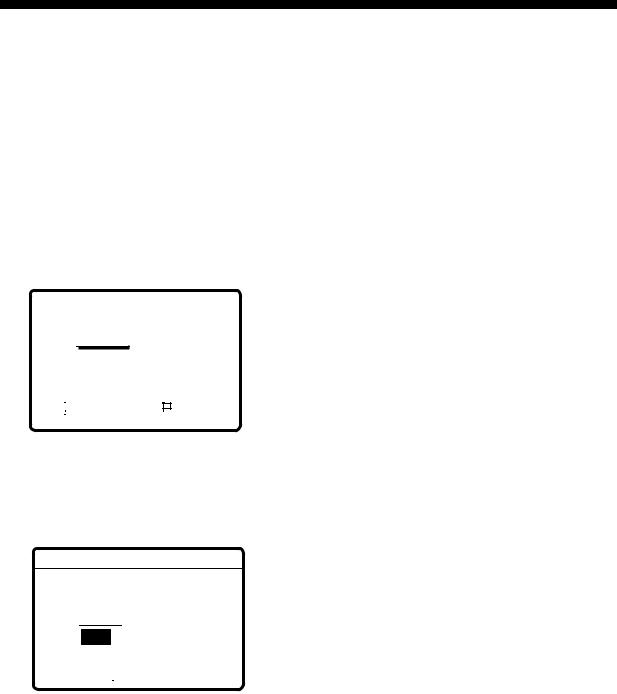
1.4 Indications
1.4.1 DSC standby screen
The DSC standby screen may be displayed by pressing the [6/SCAN] key.
Acknowledge status
(AUTO ACK or MANUAL ACK)
WATCH KEEPING |
AUTO ACK |
|
DISTRESS |
|
|
2187.5 |
4207.5 |
6312.0 |
16804.5 |
12577.0 |
8414.5 |
ROUTINE |
|
|
2177.0 |
4219.5 |
6331.0 |
16903.0 |
12657.0 |
8436.5 |
35° 00.000N |
|
MANUAL |
135° 00.000E |
23:59 |
|
Position and time. "MANUAL" shown when these are input manually.
Distress and routine frequencies scanned in clockwise direction, and frequency currently being scanned is highlighted.
One cycle is completed in less than two seconds. For how to choose scan
frequencies, see paragraph 1.6.
DSC standby screen
1.4.2 Radiotelephone screen
Press the [1/ RT/2182] key to show the radiotelephone screen. This is where you set up the radiotelephone.
|
|
|
|
|
|
|
|
|
|
|
|
|
|
|
Communications Mode |
|||||||||||||
|
|
|
|
|
|
|
|
|
|
|
|
|
|
|
||||||||||||||
|
|
|
|
|
|
|
|
|
|
|
|
|
|
|
(Duplex or Simplex, display only) |
|||||||||||||
Class of Emission (SSB, TLX, AM) |
|
|
|
|
|
MODE: SSB |
SIMP |
|
|
HIGH |
|
|
|
|
Output Power |
|||||||||||||
|
|
|
|
|
|
|
|
|
|
|||||||||||||||||||
|
|
|
|
|
|
|
CH: 200 |
|
|
|
|
|
|
|
|
|
|
|
|
|
|
|
(HIGH, MID or |
|||||
|
|
|
|
|
|
|
|
|
|
|
|
|
|
|
|
|
|
|
|
|
|
LOW) |
||||||
Channel |
|
|
|
|
|
|
|
|
|
|
|
|
|
|
|
|
|
|
|
|
|
|
|
|
|
|
|
|
TX Frequency |
|
|
|
|
|
|
TX: 2182.0 |
|
|
|
|
|
|
KHZ |
|
|
|
|
||||||||||
|
|
|
|
|
|
|
|
|
|
|
|
|
|
|
|
|||||||||||||
RX Frequency |
|
|
|
|
|
|
RX: 2182.00 |
|
|
|
|
|
|
KHZ |
|
|
|
|
||||||||||
|
|
|
|
|
|
|
|
|
|
|
|
|
|
|
|
|||||||||||||
AGC, Squelch |
|
|
|
|
|
|
|
|
|
|
|
|
|
|
|
|
Noise Blanker |
|||||||||||
|
|
|
|
|
AGC : FAST |
SQ |
NB |
|
|
|
|
|||||||||||||||||
|
|
|
|
|
|
|
|
|
||||||||||||||||||||
Sensitivity |
|
|
|
|
|
SEN |
|
|
|
|
|
|
S |
|
|
|
|
|
|
|
|
|
|
|
|
S-meter |
||
Volume |
|
|
|
|
|
VOL |
|
|
|
|
IA |
|
|
|
|
|
0.0A |
|
|
|
Antenna Current (IA) |
|||||||
|
|
|
|
|
|
|
|
|
|
|
|
|
|
|
|
|
|
|||||||||||
|
|
|
|
|
|
|
|
|
|
|
|
|
|
|
|
|
|
|
|
|
|
|
|
|
|
|
|
(or IC, VC, RF) |
Radiotelephone screen
Note: “TX” is circumscribed with a rectangle when transmitting.
1-3

1 OPERATIONAL OVERVIEW
1.5 Loudspeaker
1.Press the [7/ ] key to alternately disable or enable the loudspeaker and the alarm generated for routine messages. SOUND: ON or SOUND: OFF appears with each press.
2.To adjust loudspeaker volume do the following:
The method of adjustment depends on the setting of “VOLUME INPUT” in the Setup menu (radiotelephone).
For EASY
a)Press the [1/RT 2182] key to show the radiotelephone screen. VOL (at the bottom of the screen) is chosen.
b)Rotate the [ENTER] knob to adjust volume and then push the [ENTER] knob.
VOL |
|
|
|
|
"OFF" shown when loudspeaker is off. |
|
|
|
|
||
|
|
|
|
||
|
|
|
|
|
|
Note: For the “EASY” setting, the equipment does the following:
•“VOL” is automatically chosen after one minute even if an option other than “VOL” is selected.
•When the setting is changed to other than “VOL” and the [ENTER] knob is pushed, “VOL” is automatically chosen.
For NORMAL
a)Press the [1/RT 2182] key to show the radiotelephone screen. The last-chosen item is selected.
b)Rotate the [ENTER] knob to choose VOL at the bottom of the screen and then push the [ENTER] knob.
c)Rotate the [ENTER] knob to adjust volume and then push the [ENTER] knob.
1.6 Scanning Routine DSC Frequencies
You can scan frequencies when using the DSC mode. For how to set frequencies, see paragraph 7.4. Radiotelephone and telex are inoperative while scanning. However, in case of the FS-2570, those modes may be used during scanning when the optional internal watch keeping receiver is installed.
1.Press the [6/SCAN] key to show the DSC standby screen.
2.Press the [6/SCAN] key to start/stop scanning.
1-4
1 OPERATIONAL OVERVIEW
1.7 Automatic Acknowledge On/Off
The automatic acknowledge feature of the DSC/watch receiver automatically transmits the acknowledge back (ACK BQ) signal to the sending station when an individual, position or polling call is received. (For position and polling calls, respective item on the AUTO ACK menu must be turned on to enable automatic acknowledge.) Automatic acknowledge can be turned on or off at the DSC standby screen by the [5/ ACK/SQ] key. The message ACK: AUTO or ACK: MANUAL appears at the bottom of the DSC standby screen with each press of the key.
Note 1:To give priority to own ship’s communications while own ship is communicating, show ACK: MANUAL by the above procedure.
Note 2:Automatic acknowledge is not possible under the following conditions: Priority: Distress, Urgency or Safety
Com Type: Morse, Fax, Data, No Info Com Freq: No Info
Off Hook
1.8 Manual Entry of Position and Time
If there is no EPFS (Electronic Position-Fixing System) connected to this equipment or the EPFS connected is not working (EPFS error indication appears), manually enter position and time as follows:
1. At the DSC standby screen, press the [#/SETUP] key to display the Setup menu.
****Setup menu ****
ALARM |
SCAN FREQ |
AUTO ACK |
|
ERASE |
VOLUME |
MESSAGE |
|
POSITION |
TEST |
PRINT OUT |
SYSTEM |
2. Rotate the [ENTER] knob to choose POSITION and then push the [ENTER] knob.
** |
Position setup |
** |
|
INPUT TYPE: AUTO
LAT : 34° 41 NORTH
LON : 135° 30 EAST
TIME: 09: 00 UTC
1-5
1 OPERATIONAL OVERVIEW
3. Push the [ENTER] knob to open the INPUT TYPE menu.
** |
Position setup |
** |
|
INPUT TYPE: AUTO |
|
LAT : |
AUTO |
34° 41 NORTH |
|
|
N |
|
MANUAL |
LON : 135° 30 EAST |
|
TIME: 09: 00 UTC
Note 1:If, when INPUT TYPE is AUTO, input from the navigator is interrupted, the message “EPFS error!” appears. If this occurs, check the navigator.
Note 2:When INPUT TYPE is MANUAL, the message “Warning: Update position” appears at set intervals (update interval selected with POSITION OLDER on the Alarm menu) to ask you to update position.
4.Rotate the [ENTER] knob to choose MANUAL and then push the [ENTER] knob.
5.Push the [ENTER] knob to open the latitude input window. Use the numeric keys to enter latitude. If necessary, switch coordinates: [1] key to switch to North; [2] key to switch to South. Push the [ENTER] knob.
|
|
|
|
Position setup |
|
|
|
|
|
|
|
|
|
|
||
** |
|
|
** |
|
|
|
|
|
|
|||||||
|
|
|
|
|
|
|
|
|
|
|
||||||
|
|
INPUT TYPE: MANUAL |
|
|
|
|
|
|
3412° 30 |
NORTH |
|
|||||
|
|
LAT : |
34° |
41 NORTH |
|
|
|
|
|
|
|
|
|
|||
|
|
34˚ 41 |
|
|
3412° 30 NORTH |
|
|
|
|
|
|
NORTH: [1] KEY |
||||
LON : 135° |
30 EAST |
|
|
|
After last digit |
|||||||||||
|
|
|
|
|
SOUTH: [2] KEY |
|||||||||||
|
|
TIME: |
09: |
00 UTC |
|
|
|
is entered |
|
|
|
|
||||
|
|
|
|
|
|
|
|
|
||||||||
6.Push the [ENTER] knob to open the longitude input window. Use the numeric keys to enter longitude. If necessary, switch coordinates: [1] key to switch to East; [2] key to switch to West. Push the [ENTER] knob.
|
|
|
|
Position setup |
|
|
|
|
|
|
|
|
|
|||
** |
|
** |
|
|
|
|
|
|
|
|||||||
|
|
|
|
|
|
|
|
|
|
|
|
|||||
|
INPUT TYPE: MANUAL |
|
|
|
|
|
|
|
|
|
||||||
|
|
LAT : |
34° 30 NORTH |
|
|
|
|
|
|
|
|
|
||||
|
|
LAT: |
34˚ 41 NORTH |
|
|
|
|
|
|
13512° 30 |
EAST |
|
||||
|
|
LON : 135: |
|
135˚° 30 EAST30 EAST |
|
|
|
|
|
|
|
|
|
|||
|
|
|
|
|
|
|
13512° 30 EAST |
|
|
|
|
|
|
EAST: [1] KEY |
||
|
|
TIME: 09: |
00 UTC |
|
|
|
After last digit |
|
||||||||
|
|
|
|
|
|
WEST: [2] KEY |
||||||||||
|
|
|
|
|
|
|
|
|
|
|
|
|||||
|
|
|
|
|
|
|
|
|
|
|
is entered |
|
|
|
|
|
|
|
|
|
|
|
|
|
|
|
|
|
|
|
|
||
7. Push the [ENTER] knob to open the time input window.
 Position setup
INPUT TYPE: MANUAL
LAT : 34° 30 NORTH
LAT : 34˚ 41 NORTH
LONL : 135: °135˚30 EAST30 EAST
TIME:I 09:: 009:UTC00 UTC
12 : 34
8.Enter UTC time with the numeric keys and then push the [ENTER] knob. The Setup menu appears.
9.Press the [CANCEL] key to return to the DSC standby screen.
1-6
1 OPERATIONAL OVERVIEW
1.9 System Characteristics
1.9.1 Equipment priority
Equipment priority order is as below.
1.DMC
2.Control unit sending distress alert
3.Control unit 1 – routine use
4.Control unit 2 – routine use
5.NBDP
1.9.2 Controls become inoperative
Controls become inoperative in the following conditions:
•Controls of idle control unit in the two-control unit system when other control unit goes OFF HOOK.
•Controls of idle control unit in the two-control unit system when other control unit switches to the DSC mode.
•Distress received by DMC (Distress Message Controller).
•NBDP is scanning or communicating.
•Distress alert or distress relay is transmitted.
•Call other than distress is transmitted (transmission time about 8 s). If it becomes necessary to unlock the keyboard before the message is transmitted, press the [CANCEL] key to cancel the call.
1.9.3 Controls become operative
Controls become operative in the following conditions:
•[DISTRESS] button is pressed.
•Control unit having highest priority is operated.
•Other control unit in two-control unit system goes ON HOOK.
•Distress received by DMC is acknowledged.
•NBDP stops scanning or communicating.
1.9.4 Automatic setting of working frequency
The radiotelephone automatically sets working frequency in the following conditions:
•ABLE ACK is sent in response to individual call.
•Your ship receives ABLE ACK in response to own ship-initiated individual call.
•Your ship sends all ship call.
•Your ship sends distress relay.
•Your ship sends distress alert.
•Your ship receives group call or area call.
•Your ship receives distress relay call.
•Your ship receives distress alert.
1-7
1 OPERATIONAL OVERVIEW
1.10 Power Supply Unit (option)
The control unit works directly on 24 VDC or through a Power Supply Unit on AC mains supply (115 or 230 VAC). The power supply unit is type PR-300, supplying 24 VDC power (20 A) to the FS-1570 or type PR-850A, supplying 24 VDC (40 A) to the FS-2570. Both 115/230 VAC and 24 VDC power can be connected simultaneously. In this case, the system normally operates on the AC mains supply and when AC power is lost, the PSU automatically switches to the DC power source.
This power supply arrangement satisfies the GMDSS requirements. The FS-1570/FS-2570 can be operated directly from 24 VDC without a power supply.
OVEN power supply: The crystal oven is always powered even when the Power Switch is OFF, provided the mains switchboard is turned on.
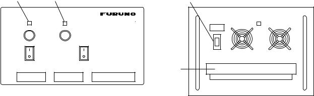
AC and DC power switches
Both AC and DC power switches on the PSU can be always kept on. (These switches are provided to turn off the power supply for maintenance.) The control unit may be turned on or off with the PSU kept on.
Red Light |
Green Light |
Breaker |
Power Lamp |
|
|
|
PR-300 |
|
100V |
10A |
125V 20A |
|
|
220V |
5A |
|
|
|
|
|
|
||
|
ON |
ON |
|
|
|
OFF |
OFF |
|
|
|
AC IN |
DC IN |
DC OUT |
Terminal |
|
L N G |
+ - |
+ - 24V + - |
Cover
Lamp (red): Lights when AC power source is in use. Lamp (green): Lights when DC power source is in use
PR-300
POWER
ON
ON
OFF
AC INPUT 50/60Hz |
DC OUTPUT |
PR-850A
Power supply units
Note: Both lamps light when changing to DC power supply (PR-300). These lamps also light when the internal temperature goes too high.
1-8
2SSB RADIOTELEPHONE
You can enter desired frequency by channel or TX and RX frequencies. The handset may be ON HOOK or OFF HOOK. To set the SSB radiotelephone to 2182 kHz/J3E automatically, press the [1/ RT/2182] key more than two seconds.
2.1 Transmitting
After selecting class of emission and frequency, you can transmit by pressing the PTT switch on the handset. Output power is shown on the display.
2.1.1 Choosing class of emission
1.At the radiotelephone screen, choose class of emission (mode) as follows:
Rotate the [ENTER] knob to choose MODE and then push the [ENTER] knob.
MODE: |
|
SSB |
|
SIMP |
HIGH |
|||||||
CH: |
|
|
TLX |
|
|
|
|
|
||||
800 |
|
|
|
|
|
|||||||
|
|
|
|
AM |
|
|
|
|
|
|||
TX: |
2182.0 |
|
|
|
KHZ |
|||||||
RX: 2182.00 |
|
|
|
KHZ |
||||||||
|
|
|
|
|
|
|
|
|
||||
AGC : FAST |
|
|
|
|
|
|||||||
SEN |
|
|
|
|
|
|
S |
|
|
|
||
|
|
|
|
|
|
|
|
|
||||
VOL |
|
|
|
|
|
|
IA |
|
|
|
0.0A |
|
|
|
|
|
|
|
|
|
|
||||
Rotate the [ENTER] knob to choose mode desired and then push the [ENTER] knob. SSB: Single Sideband, TLX: Telex, AM: AM. (You cannot transmit on the AM mode.)
2.AGC is automatically selected according to mode. AGC FAST: SSB, AGC OFF: TLX, AGC SLOW: AM. However, you may change it as below.
a)Rotate the [ENTER] knob to choose AGC and then push the [ENTER] knob.
MODE: SSB SIMP HIGH
CH: 200
TX: 2182.0 |
|
|
|
KHZ |
||||||||
RX: |
2182.00 |
|
|
|
|
KHZ |
||||||
|
|
|
OFF |
|
|
|
|
|
|
|
||
|
|
|
|
FAST |
|
|
|
|
|
|
||
AGC : |
FAST |
|
|
|
|
|
|
|||||
|
|
|
FAST |
|
|
|
|
|
|
|||
SEN |
|
|
SLOW |
S |
|
|
|
|
|
|||
|
|
|
FAST |
|
|
|
|
|
|
|||
|
|
|
|
|
|
|
|
|||||
VOL |
|
|
|
|
|
|
IA |
|
|
|
0.0A |
|
b)Rotate the [ENTER] knob to choose OFF, SLOW or FAST as appropriate and then push the [ENTER] knob.
2-1

2 SSB RADIOTELEPHONE
2.1.2 Choosing channel, frequency
Choosing channel
1. Rotate the [ENTER] knob to choose CH and then push the [ENTER] knob.
MODE: SSB SIMP HIGH
CH: 8 |
|
|
|
|
|
|
|
||||||
200 |
|
|
|
|
|
|
|
||||||
TX: |
|
2182.0 |
|
|
|
|
KHZ |
||||||
RX: 2182.00 |
|
|
|
KHZ |
|||||||||
|
|
|
|
|
|
|
|
|
|
||||
AGC : FAST |
|
|
|
|
|
|
|||||||
SEN |
|
|
|
|
|
S |
|
|
|
|
|
||
|
|
|
|
|
|
|
|
|
|
||||
VOL |
|
|
|
|
IA |
|
|
|
0.0A |
||||
|
|
|
|
|
|
|
|||||||
|
|
|
|
|
|
|
|||||||
2.Channel can be entered directly with the numeric keys, or by using the [ENTER] knob. See below for details.
Entering band and band channel with the numeric keys: Use the numeric keys to enter band and band channel and then push the [ENTER] knob.
Choosing band and band channel with the ENTER knob:
a)Use the [FILE/CURSOR] key to place the cursor in the band or band channel position, whichever you want to change.
|
|
|
|
|
|
|
|
|
|
|
|
200 |
|
|
|
|
|
200 |
|
||
|
|
|
|
|
|
|
|
|
|
|
Cursor position for |
Cursor position for |
|||||||||
selection of band channel |
selection of band |
|||||||||
b) Rotate the [ENTER] knob to set band (or channel) desired.
2 |
4 6 |
8 12 16 18 22 25 |
01 02----- 029 |
|
|
ITU band |
User band |
Setting Range |
|
|
|
ITU |
Band: |
2/4/6/8/12/16/18/22/25 |
|
User Band: |
001-029 (leadiing zero necessary) |
||
ITU Channel: |
XX01 - XX236 (rendering on band or mode) |
||
User Channel: |
XXX01 - XXX99 |
|
|
c)Push the [ENTER] knob. The TX and RX frequencies of the channel entered appear.
2-2

2 SSB RADIOTELEPHONE
Choosing frequency
1.Rotate the [ENTER] knob to choose TX or RX as appropriate and then push the [ENTER] knob.
MODE: AM SIMP HIGH
CH: 200
|
TX: 2182.0 |
|
KHZ |
||||||||
|
|
|
|
|
|
|
|||||
|
Rx: |
|
|
21823456.00 KHZ.78 |
KHZ |
||||||
|
|
|
|
|
|
|
|
|
|
|
|
|
AGC : |
|
|
|
|
|
|
|
|||
|
SLOW |
|
|
|
|||||||
SEN |
|
|
|
|
|
|
S |
|
|
|
|
|
|
|
|
|
|
|
|
||||
VOL |
|
|
|
|
|
|
IA |
|
|
0.0A |
|
|
|
|
|
|
|
|
|||||
2.Enter frequency by one of the methods below.
Entering frequency with the numeric keys:
Use the numeric keys to enter frequency and then push the [ENTER] knob. Be sure to including trailing zero. For example, to enter 2161 kHz, key in [2], [1], [6], [1], [0]. (Keying in 2-1-6-1 will set 216.1 kHz.)
Choosing frequency with the ENTER knob (for RX only):
a)Use the [FILE/CURSOR] key to choose digit to change.
b)Rotate the [ENTER] knob to set digit.
c)Push the [ENTER] knob.
Note: To enter same frequency for both TX and RX, enter the TX frequency first.
2.1.3 Tuning
Maximum transmission power is achieved only when the antenna impedance and transmitter impedance match each other. Because the antenna impedance changes with frequency, a means must be provided to match (tune) the antenna impedance with the transmitter impedance. This is done with the antenna coupler. The antenna coupler automatically tunes the transmitter to a wide range of different antenna lengths, from 7 to 30 m.
To initiate the automatic tuning, do the following:
1.Press the PTT switch on the handset or the [LOG/TUNE] key on the control unit. “TUNING” appears when the [LOG/TUNE] key is pressed; “TX” pops out when the PTT switch is pressed.
Tuning will be completed within 2 to 5 s for a newly selected frequency, or less than 0.5 s for a once-tuned frequency. (A memory saves coil and capacitor settings.) When the tuning process is successfully completed, TUNE: OK appears. If tuning fails, TUNE:
NG appears.
2-3
2 SSB RADIOTELEPHONE
Note: When tuning is initiated in the two-control unit system, the display of the idle control unit shows “OCCUPIED(ANOTHER CONTROLLER).” In this case, only the DISTRESS button is operative on the idle control unit. Further, if a control unit is in use when tuning is attempted at the other control unit, the display of the control unit which attempted to tune shows “OCCUPIED” plus the name of the equipment in use: ANOTHER CONTROLLER, NBDP, or DMC.
2.1.4 Using the handset
Hold the handset close to your mouth, press the PTT switch and speak clearly.
2.1.5 Monitoring transceiver output power
During transmission, the IA bar deflects according to the current being fed to the antenna feeder from the antenna coupler. The unit of readout is amperes. The antenna current varies with the effective antenna impedance. The swing differs by the frequency and antenna length. The output power is proportional to the square of an antenna current.
Note: If IA is not shown, follow the procedure in paragraph 2.1.7 to show it.
MODE: SSB SIMP HIGH
CH: 200
TX: 2182.0 |
|
|
|
KHZ |
|
|
|||||||
RX: 2182.00 |
|
|
|
KHZ |
|
|
|||||||
|
|
|
|
|
|
|
|
|
|||||
AGC : FAST |
|
|
|
|
|
|
|
|
|||||
SEN |
|
|
|
|
|
S |
|
|
|
|
|
Antenna Current |
|
|
|
|
|
|
|
|
|
|
|
||||
VOL |
|
|
|
|
IA |
|
|
|
2.1A |
|
|||
|
|
|
|
||||||||||
|
|
|
|
|
|
|
|
||||||
2-4
 Loading...