


 Loading...
COLOR LCD SOUNDER
MODEL FCV-582L

C
9 - 5 2 , A s h i h a r a - c h o , N i s h i n o m i y a , J a p a n
Tel ephone : |
0798 |
- 65 |
- 2 111 |
Tel efax : |
0798 |
- 65 |
- 420 0 |
Al l rights reserved . |
Printed in Japan |
|
PUB. No. OME-23590 |
(Y OS H) |
FCV582L |
 You r Loc a l A gent/Deal e r
FIRST EDITION |
: |
APR . |
1998 |
H |
: |
MAR . |
13 , 200 1 |
 SAFETY INSTRUCTIONS
 WARNING
ELECTRICAL SHOCK HAZARD
Do not open the equipment.
Only qualified personnel should work inside the equipment.
Immediately turn off the power at the switchboard if water leaks into the equipment.
Continued use of the equipment can cause fire or electrical shock. Contact a FURUNO agent for service.
Do not disassemble or modify the equipment.
Fire, electrical shock or serious injury can result.
Immediately turn off the power at the switchboard if the equipment is emitting smoke or fire.
Continued use of the equipment can cause fire or electrical shock. Contact a FURUNO agent for service.
Make sure no rain or water splash leaks into the equipment.
Fire or electrical shock can result if water leaks in the equipment.
 WARNING
Keep heater away from equipment.
A heater can melt the equipment’s power cord, which can cause fire or electrical shock.
Use the proper fuse.
Use only a 3A fuse. Use of a wrong fuse can result in equipment damage and void the warranty.
 CAUTION
A warning label is attached to the equipment. Do not remove the label. If the label is peeling off or is illegible, contact a FURUNO agent or dealer.
 About the TFT LCD
The TFT LCD is constructed using the latest LCD techniques, and displays 99.99% of its pixels. The remaining 0.01% of the pixels may drop out or blink, however this is not an indication of malfunction.
i

TABLE OF CONTENTS
FOREWORD ....................................... |
iii |
INTERPRETING THE DISPLAY |
|||
MENU TREE ....................................... |
iv |
3.1 |
Zero Line ............................................. |
19 |
|
SYSTEM CONFIGURATION ....... |
v |
3.2 |
Fish School Echoes .............................. |
19 |
|
PRINCIPLE OF OPERATION |
vi |
3.3 |
Bottom Echo ........................................ |
19 |
|
3.4 |
Surface Noise/Aeration |
20 |
|||
|
|
||||
OPERATIONAL OVERVIEW
1.1 |
Control Description ............................... |
1 |
|
1.2 |
Indications, Markers .............................. |
2 |
|
1.3 Turning On/Off the Power ..................... |
3 |
||
1.4 |
Adjusting Tone and Brilliance ............... |
3 |
|
1.5 |
Selecting a Display ................................ |
3 |
|
1.6 |
Selecting Display Range ........................ |
7 |
|
1.7 |
Adjusting the Gain ................................. |
7 |
|
1.8 Automatic Operation.............................. |
8 |
||
1.9 |
Selecting Picture Advance |
|
|
|
Speed ..................................................... |
8 |
|
1.10 |
Erasing Weak Echoes .......................... |
9 |
|
1.11 Measuring Depth ................................. |
9 |
||
1.12 A-scope Display ................................. |
10 |
||
1.13 |
User Menu ......................................... |
10 |
|
1.14 |
Suppressing Interference ................... |
11 |
|
1.15 |
Suppressing Low Level Noise ........... |
11 |
|
1.16 |
Selecting Background and |
|
|
|
|
Echo Colors ....................................... |
11 |
1.17 Alarms ................................................ |
12 |
||
1.18 White Marker ..................................... |
13 |
||
1.19 |
Fine Adjustment of Gain in |
|
|
|
|
Dual-Frequency Operation ................ |
13 |
OPTIONAL MODE
2.1 |
Displaying the Optional Mode Menu .. |
15 |
2.2 System Menu ....................................... |
15 |
|
2.3 |
Demonstration Display ........................ |
17 |
2.4 |
Bottom Level ....................................... |
17 |
2.5 TVG Level ........................................... |
18 |
|
2.6 |
Echo Offset .......................................... |
18 |
MAINTENANCE & |
|
|
TROUBLESHOOTING |
|
|
4.1 |
Checking .............................................. |
21 |
4.2 |
Cleaning the Display Unit ................... |
21 |
4.3 Transducer Maintenance ...................... |
21 |
|
4.4 |
Replacing the Fuse ............................... |
21 |
4.5 |
Troubleshooting ................................... |
22 |
4.6 |
Test ....................................................... |
23 |
4.7 |
Test Pattern .......................................... |
23 |
4.8 |
Clearing the Memory ........................... |
24 |
SPECIFICATIONS ....................... |
SP-1 |
|
INDEX ............................................ |
Index-1 |
ii

FOREWORD
A Word to FCV-582L Owners
Congratulations on your choice of the FURUNO FCV-582L Color LCD Sounder. We are confident you will see why the FURUNO name has become synonymous with quality and reliability.
For over 50 years FURUNO Electric Company has enjoyed an enviable reputation for innovative and dependable marine electronics equipment. This dedication to excellence is furthered by our extensive global network of agents and dealers.
This equipment is designed and constructed to meet the rigorous demands of the marine environment. However, no machine can perform its intended function unless operated and maintained properly. Please carefully read and follow the recommended procedures for operation and maintenance.
We would appreciate hearing from you, the end-user, about whether we are achieving our purposes.
Thank you for considering and purchasing FURUNO equipment.
Features
The FURUNO FCV-582L is a dual-frequency (50 kHz and 200 kHz) color LCD sounder. Comprised of a display unit and a transducer, the FCV-582L displays underwater conditions in 16 colors (including background) on a bright 6.5-inch color TFT (Thin Film Transistor) LCD.
The main features of the FCV-582L are
•Compact design permits installation where space is limited.
•Bright 6.5-inch color LCD with temperature compensated tone and brilliance control.
•Wide variety of display modes: bottom lock, dual frequency, marker zoom, bottom zoom, nav data and graphic display.
•Automatic function permits unattended adjustment of range and gain. The range scale and gain automatically change to display the bottom in reddish-brown on the lower half of the screen.
•Navigation data display (requires navigation data input from external navigator) provides position, course, speed, depth, temperature and waypoint data indications.
•Alarms: Bottom, Fish (bottom-lock, normal), Temperature (within, over range set).
•A-scope display discriminates bottom fish, vital for bottom trawler and trap users.
•Universal 10.2–31.2 VDC power supply consuming less than 20 W power.
iii
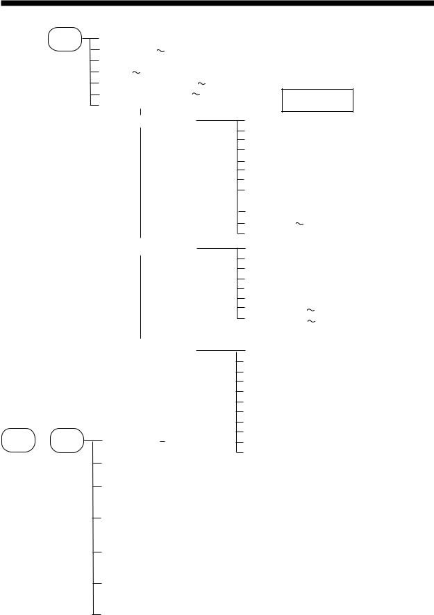
MENU TREE
MENU
ESC
USER MENU
NOISE LIMITER (OFF, NL1, NL2, NL3) CLUTTER (0 16) Default: 9 MARKER(VRM,WHITE,MARKER)
HUE (1 9) Default: 1 |
|
GAIN ADJ 200kHz (-20 |
+20) Default: 0 |
GAIN ADJ 50kHz (-20 |
+20) Default: 0 |
GO TO SYSTEM MENU (+)
Default settings shown in bold.
SYSTEM MENU 1
SYSTEM MENU 2
MENU (1, 2, 3)
DEPTH UNIT (m, ft, fa, pb) SPEED UNIT (kt, MPH, km/h) TEMP UNIT (° C, ° F)
ZOOM MARK (OFF, ON)
F/A LEVEL (WEAK, MED, STRG) TEMP GRAPH (OFF, ON)
LANG (English, 
 , French, Spanish, German, Italian)
DISP SEL (GRA1,GRA2,DATA) DRAFT(-20 +20) Default: 0 TX OUTPUT (MIN, MAX)
MENU (1, 2, 3)
NAV DSP (OFF, L/L, R/B, CSE) NMEA (Ver1.5, Ver2.0) BEARING (TRUE, MAG)
SPD SEL (OFF, OWN, NMEA) TMP SEL (OFF, OWN, NMEA) SPD ADJ (-50 +50) Default: 0 TMP ADJ (-20 +20) Default: 0.0
Any +
key POWER
OPTIONAL MODE
SYSTEM MENU 3
SELF TEST ( )
CLEAR MEMORY ( )
)
DEMO ( )
)
MENU (1, 2, 3) BASIC RANGE1 (15) BASIC RANGE2 (30) BASIC RANGE3 (60) BASIC RANGE4 (120) BASIC RANGE5 (200) BASIC RANGE6 (400)
BASIC RANGE7 (1000)
BASIC RANGE8 (2500)
ZOOM RANGE (range: 7-2500, 30) (feet) B/L RANGE (10, 20) (feet)
ECHO OFFSET (SIG LEV key 3 times)
TVG SELECT (ZOOM key 3 times)
BOTTOM LEVEL (ALARM key 3 times)
TEST PATTERN (BRILL key 3 times)
iv
SYSTEM CONFIGURATION
DISPLAY
UNIT
Ship's mains 12–24 VDC
External equipment (GPS navigator, etc.)
 Speed, temperature
  sensor (option)
TRANSDUCER
FCV-582L system configuration
v

PRINCIPLE OF OPERATION
The FCV-582L determines the distance between its transducer and underwater objects such as fish, lake bottom or seabed and displays the results on its screen. It does this by utilizing the fact that an ultrasonic wave transmitted through water travels at a nearly constant speed of 4800 feet (1500 meters) per second. When a sound wave strikes an underwater object such as fish or sea bottom, part of the sound wave is reflected back toward the source. Thus by calculating the time difference between the transmission of a sound wave and the reception of the reflected sound wave, the depth to the object can be determined.
The entire process begins in the display unit. Transmitter power is sent to the transducer as a short pulse of electrical energy. The electrical signal produced by the transmitter is converted into an ultrasonic signal by the transducer and transmitted into the water. Any returning signals from intervening objects (such as a fish school) are received by the transducer and converted into an electrical signal. The signals are then amplified in the amplifier section, and finally, displayed on the screen.
The picture displayed is made up of a series of vertical scan lines, one for each transmission. Each line represents a snapshot of what has occurred beneath the boat. Series of snapshots are accumulated side by side across the screen, and the resulting contours of the bottom and fish between the bottom and surface are displayed.
Underwater conditions and video sounder display
vi

OPERATIONAL OVERVIEW
1.1 Control Description
All operations of the FCV-582L are carried out with the controls on the front panel of the display unit. All controls respond immediately to your command and the unit emits a beep to signify correct key sequence. (Invalid key input emits several beeps.)
SHIFT
∙ Shift VRM. (p. 9)
∙ MARKER
Select menu items. (p. 10)
ADVANCE
Selects zoom mode. (p. 3)
ZOOM |
SIG LEV |
A-SCOPE
Adjusts display brilliance and tone. (p. 3)
∙Rotate to adjust gain. (p. 7)
∙Push to turn automatic operation on/off. (p. 7)
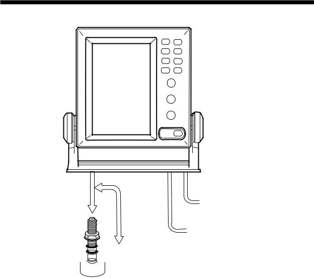
Removing cover
While pressing the center of the cover with your thumbs as illustrated, pull the cover towards you to remove it.
BRILL |
ALARM |
4 |
5 |
3 |
6 |
2 |
7 |
1 |
8 |
RANGE |
|
4 |
6 |
|
PUSH |
|
AUTO |
2 |
8 |
0 |
10 |
GAIN |
|
DUAL |
|
LF |
HF |
ZOOM |
ZOOM |
NAV |
MENU |
MODE
POWER
∙Shift display range. (p. 7)
∙Select menu options. (p. 10)
Removes weak echoes. (p. 9)
Selects picture advance speed. (p. 8)
Sets alarms. (p. 12)
Turns A-scope display on/off. (p. 10)
Selects range. (p. 7)
Selects display mode. (p. 3)
Turns power on/off. (p. 3)
Figure 1-1 Controls
1
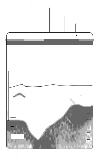
1.2 Indications, Markers
The figure below shows all indications and markers which may appear in the normal display. The combination displays (normal display plus marker or zoom display) may additionally display the zoom marker.
Speed*
Noise Limiter
Transducer frequency
Alarm icon
Water |
|
|
|
|
22.6°C 12kt NL1 200k |
|
F/NM |
|
|
|
|
|
Active alarm |
|||||||||||||||||||
|
|
|
|
|
|
|
|
|
|
|||||||||||||||||||||||
|
|
|
|
|
|
|
|
|
||||||||||||||||||||||||
|
|
|
|
|
|
|
|
|
|
|||||||||||||||||||||||
temperature* |
|
|
|
|
|
|
|
|
|
|
|
|
|
|
|
|
0 |
|
|
|
|
|
|
|
|
|
|
Minute marker |
||||
|
|
|
|
|
|
35°15.000’ N |
|
|
|
|
|
|
|
|
|
|
|
|
|
|
|
|
||||||||||
Nav data* |
|
|
|
|
|
|
|
|
135°07.500’ E |
|
|
|
|
|
|
|
|
|
|
|
|
|
|
(yellow, blue, |
||||||||
|
|
|
|
|
|
|
|
|
|
|
|
|
|
|
|
|
|
|||||||||||||||
|
|
|
|
|
|
|
|
|
|
|
|
|
|
|
|
|
|
|
|
|
|
|
|
|
|
|
|
|
|
|
|
30 sec. each) |
Water temperature |
|
|
|
|
|
|
|
|
30 |
|
|
|
|
|
|
|
|
|
|
|
|
|
|
|
|
|
|
|||||
|
|
|
|
|
|
|
|
|
|
|
|
|
|
|
|
|
|
|
|
|
|
Range scale |
||||||||||
|
|
|
|
|
|
|
|
|
|
|
|
|
|
|
|
|
|
|
|
|
|
|||||||||||
|
|
|
|
|
|
|
|
|
|
|
|
|
|
|
|
|
|
|
|
|
|
|
|
|
|
|
|
|||||
|
|
|
|
|
|
|
|
|
|
|
|
|
|
|
|
|
|
|
|
|
|
|
|
|
|
|
|
|||||
scale* |
|
|
|
|
|
|
|
|
|
|
|
|
|
|
20 |
|
|
|
|
|
|
|
|
|
|
|||||||
|
|
|
|
|
|
|
|
|
|
|
|
|
|
|
|
|
|
|
|
|
|
|
|
|||||||||
|
|
|
|
|
|
|
|
|
|
|
|
20 |
|
|
|
|
|
|
|
|
|
|
|
|
|
|
|
Alarm zone |
||||
|
|
|
|
|
|
|
|
|
|
|
|
|
|
|
|
|
|
|
|
|
|
|
|
|
|
|
||||||
|
|
|
|
|
|
|
|
|
|
|
|
|
|
|
|
|
|
|
|
|
|
|
|
|
|
|
|
|
|
|||
|
|
|
|
|
|
|
|
|
|
|
|
|
|
|
|
|
|
|
|
|
|
|
|
|
|
|
|
|
|
|||
|
|
|
|
|
|
|
|
|
|
|
|
|
|
|
|
|
|
|
|
|
|
|
|
|
|
|
|
|
|
|||
Water temperature |
|
|
|
|
|
|
|
|
|
|
|
|
|
|
|
|
|
|
|
|
|
|
|
|
|
marker |
||||||
|
|
|
|
|
|
|
|
|
|
|
|
|
|
|
|
|
|
|
|
|
|
|
||||||||||
|
|
|
|
|
|
|
|
|
|
|
|
|
|
|
|
|
|
|
|
|
||||||||||||
marker (orange)* |
|
|
|
|
|
|
|
|
|
|
|
|
|
|
|
|
|
|
|
|
|
|
|
|
|
|
|
|
Variable range |
|||
|
|
|
|
|
|
|
|
|
|
|
|
|
|
|
|
|
|
|
|
|
|
|
|
|
|
|
||||||
|
|
|
|
|
|
|
|
|
|
|
|
|
|
|
|
|
|
|
|
|
|
|
|
|
|
|
||||||
|
|
|
|
|
|
|
|
|
|
|
|
|
|
|
|
|
|
|
|
|
|
|
|
|
|
|
||||||
|
|
|
|
|
|
39.8 |
40 |
|
|
|
|
|
|
|
|
|
|
|||||||||||||||
|
|
|
|
|
|
|
|
|
|
|
|
|
|
|
|
|||||||||||||||||
|
|
|
|
|
|
|
|
|
|
|
|
10 |
|
|
|
|
|
|
|
|
|
|
|
|
|
|
|
marker (green) |
||||
|
|
|
|
|
|
|
|
|
|
|
|
|
|
|
|
|
|
|
|
|
|
|
|
|
|
|
|
w/depth readout |
||||
|
|
|
|
|
|
|
|
|
|
|
|
|
|
|
|
|
|
|
|
|
|
|
|
|
|
|
|
|
|
|
|
|
|
|
|
|
|
|
|
|
|
|
|
|
|
|
|
|
|
|
|
|
|
|
|
|
|
|
|
|
|
|
|
|
|
|
|
|
|
|
|
|
|
|
|
|
|
|
|
|
|
|
|
|
|
|
|
|
|
|
|
|
|
|
|
|
|
|
|
|
|
|
|
|
|
|
|
|
|
|
|
|
|
|
|
|
|
|
|
|
|
|
|
|
|
|
|
|
|
|
|
|
|
|
|
|
|
|
|
|
|
|
|
|
|
|
|
|
|
|
|
|
|
|
|
|
|
|
|
|
|
|
|
|
Color |
0 |
|
|
bar |
60 |
||
|
|||
|
|
All indications and |
|
Demonstration |
|
markers are displayed |
|
(DEMO) |
in white unless |
||
mode |
49.6 |
80 |
|
|
|
noted otherwise. |
|
|
Depth |
* Requires appropriate sensor. |
Figure 1-2 Indications
2
1.3 Turning On/Off the Power
Press the POWER key to turn the power on/ off. When the unit is turned on it proceeds in the sequence shown below.
ROM: OK |
ROM and RAM |
|
RAM: OK |
check; displayed for |
|
several seconds. |
||
|
Note 1: Location of arrow keys on the brilliance setting is opposite of same controls on the control panel.
Note 2: Tone or brilliance must be adjusted within about 10 seconds after pressing the BRILL key or the tone and brilliance display will be erased.
PROGRAM No: 02522790** ** Program version no.
You may press any key to show the sounder display immediately.
|
200k |
Sounder |
0.0 |
0 |
|
|
|
display |
|
20 |
|
|
40 |
|
|
60 |
|
49.6 |
80 |
|
Figure 1-3 Start-up sequence
Note: Wait at least five sec. before reapplying the power.
1.4 Adjusting Tone and Brilliance
1.Press the BRILL key. The tone and brilliance setting display appears.
|
|
LOW– |
|
|
|
|
|
|
|
|
+HIGH |
||||||||||
TONE : |
5 |
|
|
|
|
|
|
|
|
|
|
|
|
|
|
|
|
|
|
|
|
|
|
|
|
|
|
|
|
|
|
|
|
|
|
|
|
|
|
|
|
||
|
|
LOW▼ |
|
|
|
|
|
|
|
|
▲HIGH |
||||||||||
BRILL : |
7 |
|
|
|
|
|
|
|
|
|
|
|
|
|
|
|
|
|
|
|
|
|
|
|
|
|
|
|
|
|
|
|
|
|
|
|
|
|
|
|
|
||
|
|
|
|
|
|
|
|
|
|
|
|
|
|
|
|
|
|
|
|
|
|
Figure 1-4 Tone and brilliance setting display
2.Press the [+] or [–] key to adjust display tone.
3.Press the [▲] or [▼] key to adjust display brilliance.
1.5 Selecting a Display
Six basic displays are available: nav (data or graphic mode selectable on the system menu), low frequency, dual frequency, high frequency, zoom (marker zoom, bottom zoom, bottom lock), and menu. (An A-scope display is also available with the BRILL and ALARM keys.)
1.Operate the MODE control to select a display mode.
2.For zoom mode, press the ZOOM key.
ZOOM MODE
▲BOTTOM LOCK BOTTOM ZOOM
▼ MARKER ZOOM
Figure 1-5 Zoom mode selection display
Normal display
Low frequency (50 kHz) display
The sounder uses ultrasonic pulses to detect bottom conditions. The lower the frequency of the pulse, the wider the detection area. Therefore, the 50 kHz frequency is useful for general detection and judging bottom condition.
 50 kHz
200 kHz
Figure 1-6 Comparison of detection ranges of 50 kHz and 200 kHz transducers
3
Loading...