


 Loading...
OPERATOR'S MANUAL
FACSIMILE RECEIVER
MODEL FAX-408
www.furuno.co.jp

The paper used in this manual is elemental chlorine free.
FURUNO Authorized Distributor/Dealer
9-52 Ashihara-cho,
Nishinomiya, 662-8580, JAPAN
Telephone : +81-(0)798-65-2111
Fax |
: +81-(0)798-65-4200 |
All rights reserved. |
Printed in Japan |
A : SEP. 2006
B : JUN. 15, 2009
Pub. No. OME-62620-B
(AKMU ) FAX-408
*00016160811*
*00016160811*
* 0 0 0 1 6 1 6 0 8 1 1 *

IMPORTANT NOTICES
General
•The operator of this equipment must read and follow the descriptions in this manual. Wrong operation or maintenance can cancel the warranty or cause injury.
•Do not copy any part of this manual without written permission from FURUNO.
•If this manual is lost or worn, contact your dealer about replacement.
•The contents of this manual and equipment specifications can change without notice.
•The example screens (or illustrations) shown in this manual can be different from the screens you see on your display. The screens you see depend on your system configuration and equipment settings.
•Save this manual for future reference.
•Any modification of the equipment (including software) by persons not authorized by FURUNO will cancel the warranty.
•All brand and product names are trademarks, registered trademarks or service marks of their respective holders.
How to discard this product
Discard this product according to local regulations for the disposal of industrial waste. For disposal in the USA, see the homepage of the Electronics Industries Alliance (http://www.eiae.org/) for the correct method of disposal.
How to discard a used battery
Some FURUNO products have a battery(ies). To see if your product has a battery(ies), see the chapter on Maintenance. Follow the instructions below if a battery(ies) is used.
In the European Union
The crossed-out trash can symbol indicates that all types of batteries |
|
|
must not be discarded in standard trash, or at a trash site. Take the |
|
|
used batteries to a battery collection site according to your national |
Cd |
|
legislation and the Batteries Directive 2006/66/EU. |
||
|
In the USA
The Mobius loop symbol (three chasing arrows) indicates that Ni-Cd and lead-acid rechargeable batteries must be recycled. Take the used batteries to a battery collection site according to local laws.
Ni-Cd Pb
In the other countries
There are no international standards for the battery recycle symbol. The number of symbols can increase when the other countries make their own recycle symbols in the future.
i
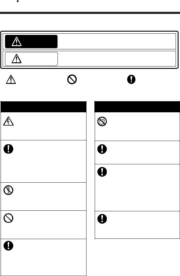
 SAFETY INSTRUCTIONS
The user and installer must read the appropriate safety instructions before attempting to install or operate the equipment.
Indicates a potentially hazardous situation which, if not avoided, WARNING could result in death or serious injury.
CAUTION |
may result in minor or moderate injury. |
|
|
Indicates a potentially hazardous situation which, if not avoided, |
|
|
|
|
Warning, Caution |
Prohibitive Action |
Mandatory Action |
|
|
|
Safety Instructions for the Operator
 WARNING
Do not open the equipment except to replace paper.
Only qualified personnel should work inside the equipment.
Immediately turn off the power at the switchboard if water leaks into the equipment or something is dropped into the equipment.
Continued use of the equipment can cause fire or electrical shock. Contact a FURUNO agent for service.
Do not disassemble or modify the equipment.
Fire, electrical shock or serious injury can result.
Do not place liquid-filled containers on the top of the equipment.
Fire or electrical shock can result if a liquid spills into the equipment.
Immediately turn off the power at the switchboard if the equipment is emitting smoke or fire.
Continued use of the equipment can cause fire or electrical shock. Contact a FURUNO agent for service.
 WARNING
Make sure no rain or water splash leaks into the equipment.
Fire or electrical shock can result if water leaks in the equipment.
Use the proper fuse.
Use of a wrong fuse can result in damage to the equipment or cause fire.
Handle the LCD with great care. Strong shock may break it.
If the LCD breaks, LCD liquid may leak out. Do not swallow or touch the liquid - it is toxic if swallowed. If it is swallowed or contacts eyes, rinse the contacted area thoroughly with water and contact a physician immediately.
The power supply shall conform to the recommended rating.
Fire or electrical shock may result if an improper power supply is used.
ii
 CAUTION
Do not use commercial cleaners to clean the main unit.
Commercial cleaners may remove paint and markings. Remove dust from the main unit with a soft cloth. For stubborn dirt, use water-diluted mild detergent and a soft cloth.
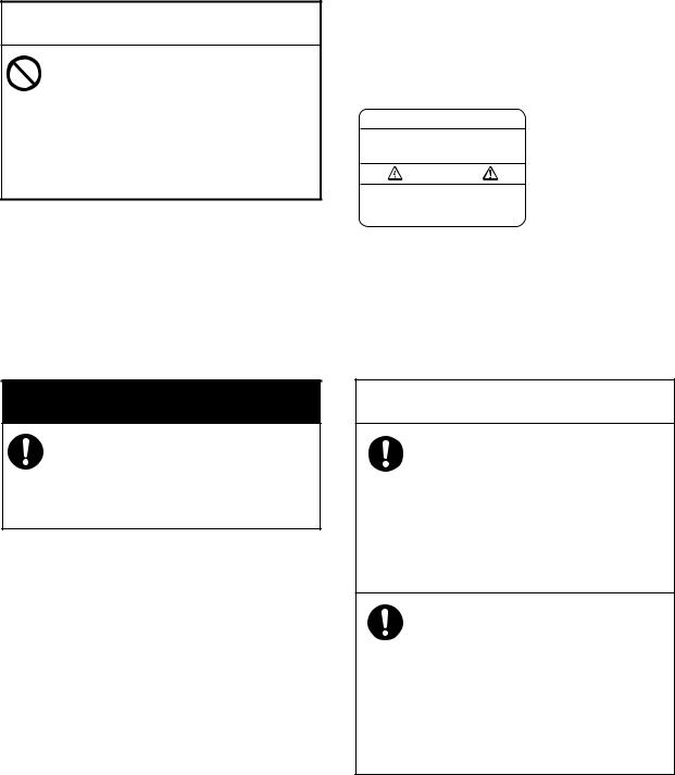
WARNING LABEL
A warning label is attached to the main unit. Do not remove the label. If the label is missing or damaged, contact a FURUNO agent or dealer about replacement.
 WARNING
To avoid electrical shock, do not remove cover. No user-serviceable parts inside.
Name: Warning Label 1
Type: 86-003-1011-2
Code No.: 100-236-232-10
Safety Instructions for the Installer
 WARNING
Turn off the power at the switchboard before beginning the installation.
Fire or electrical shock can result if the power is left on.
 CAUTION
Observe the following compass safe distances to prevent interference to a compass:
|
Standard |
Steering |
|
|
compass |
compass |
|
|
|
|
|
Facsimile |
0.7 m |
0.5 m |
|
Receiver |
|||
|
|
||
|
|
|
Observe the following cautions when choosing a mounting location:
-Locate away from area subject to rain or water splash.
-Provide adequate ventilation.
-Locate out of direct sunlight.
-Choose location where shock and vibration are minimal.
iii
TABLE OF CONTENTS
|
|
|
|
|
FOREWORD |
............................................................................................... |
vi |
||
EQUIPMENT .....................................................................................LIST |
vii |
|||
SYSTEM CONFIGURATION .................................................................... |
viii |
|||
1. |
OPERATION .......................................................................................... |
1 |
||
|
1.1 |
Control .......................................................................................................Description |
1 |
|
|
1.2 |
Turning .............................................................................................the Power On/Off |
3 |
|
|
1.3 |
Adjusting ................................................................................................LCD Contrast |
3 |
|
|
1.4 |
Adjusting ..............................................................LCD Brilliance and LED Brightness |
3 |
|
|
1.5 |
Channel .................................................................................and Frequency Displays |
3 |
|
|
|
1.5.1 ................................................................................................ |
Channel setting |
3 |
|
|
1.5.2 ......................... |
Selection of desired frequency, fine adjustment of frequency |
4 |
|
1.6 |
Automatic .....................................................................................................Receiving |
4 |
|
|
1.7 |
Manual .........................................................................................................Receiving |
5 |
|
|
1.8 |
Timer Receiving............................................................................................................ |
5 |
|
|
|
1.8.1 ............................................................................. |
Registering timer programs |
5 |
|
|
1.8.2 .................................................. |
Choosing timer programs for timer reception |
6 |
|
|
1.8.3 ......................................... |
Disabling timer operation when awaiting reception |
7 |
|
|
1.8.4 ............................................... |
Unlocking the keyboard during timer reception |
7 |
|
|
1.8.5 .............................................................................. |
Confirming timer programs |
7 |
|
1.9 |
Processing .......................................................................................Facsimile Images |
8 |
|
|
|
1.9.1 ................................................................................................ |
Speed and IOC |
8 |
|
|
1.9.2 ............................................................................................... |
Manual phasing |
9 |
|
|
1.9.3 ............................................................................................... |
Synchronization |
9 |
|
|
1.9.4 ................................................................................................. |
Reverse mode |
9 |
|
1.10 |
Sleep Timer ................................................................................................................ |
10 |
|
|
|
1.10.1 .............................................................................. |
Activating the sleep timer |
10 |
|
|
1.10.2 ................................................................................. |
Unlocking the keyboard |
10 |
|
|
1.10.3 ............................................................................... |
Disabling the sleep timer |
10 |
|
1.11 |
Setting ..........................................................................................the Date and Time |
11 |
|
|
1.12 |
Adding ........................................................................................Facsimile Channels |
11 |
|
|
1.13 |
ISB Function ............................................................................................................... |
13 |
|
|
|
1.13.1 ..................................................................... |
Enabling, disabling ISB function |
13 |
|
|
1.13.2 ..................................................................................... |
Setting ISB shift width |
13 |
|
1.14 |
Operation ..........................................................................with an External Receiver |
14 |
|
|
|
1.14.1 ...................................................... |
Enabling, disabling external receiver use |
14 |
|
|
1.14.2 ....................................................................................................... |
Operation |
14 |
2. |
MAINTENANCE................................................................................... |
15 |
||
|
2.1 |
Cleaning ..................................................................................................................... |
15 |
|
|
2.2 |
Replacement ..............................................................................of Recording Paper |
15 |
|
|
2.3 |
Replacement .................................................................................................of Fuse |
16 |
|
|
2.4 |
Backup ...........................................................................................................Battery |
19 |
|
|
2.5 |
Clearing .......................................................................................................the RAM |
19 |
|
iv
3. INSTALLATION................................................................................... |
21 |
||
3.1 |
Main Unit .................................................................................................................... |
21 |
|
3.2 |
Antenna...................................................................................................................... |
22 |
|
|
3.2.1 |
General antenna connection ......................................................................... |
22 |
|
3.2.2 Whip or wire antenna .................................................................................... |
23 |
|
|
3.2.3 Installation of optional preamp unit (FAX-5).................................................. |
23 |
|
3.3 |
Wiring |
......................................................................................................................... |
24 |
|
3.3.1 |
Power, ground ............................................................................................... |
24 |
|
3.3.2 ....................................................................................... |
External equipment |
24 |
|
3.3.3 ....................................................................................Whip or wire antenna |
25 |
|
|
3.3.4 .......................Setting of SW S1 on RCV board (when preamp unit is used) |
26 |
|
3.4 |
Changing ......................................................................................Display Language |
27 |
|
FACSIMILE STATION ...............................................................TABLES |
29 |
||
SPECIFICATIONS................................................................................. |
SP-1 |
||
PACKING LIST......................................................................................... |
A-1 |
||
OUTLINE DRAWINGS ............................................................................. |
D-1 |
||
INTERCONNECTION .............................................................DIAGRAM |
S-1 |
||
v

FOREWORD
A Word to the Owner of the FAX-408
FURUNO Electric Company thanks you for purchasing the FURUNO FAX-408 Facsimile Receiver. We are confident you will discover why the FURUNO name has become synonymous with quality and reliability.
For over 60 years FURUNO Electric Company has enjoyed an enviable reputation for quality and reliability throughout the world. This dedication to excellence is furthered by our extensive global network of agents and dealers.
Your equipment is designed and constructed to meet the rigorous demands of the marine environment. However, no machine can perform its intended function unless properly installed and maintained. Please carefully read and follow the operation, installation and maintenance procedures set forth in this manual.
We would appreciate feedback from you, the end-user, about whether we are achieving our purposes.
Thank you for considering and purchasing FURUNO.
Features
The FAX-408 uses an Individual scanning recording thermal head to produce high quality facsimile images.
•Electronic scanning with thermal head recording system provides clear image, quiet operation.
•Programmed with all existing facsimile stations and frequencies. User may also program channels and edit existing channels.
•Fully automatic facsimile operation with built-in schedule timer. Storage for 16 timer programs.
•Fully automatic selection of speed, IOC, phase alignment and frequency. Manual selection also available.
•9-tone gradation recording provides clear and detailed weather images.
•ISB shift function tracks frequency of SSB multiplex broadcasts whose frequencies typically shift 1-2 kHz.
•Signal from external receiver may also be recorded.
•Automatic start/stop circuit provided in accordance with WMO standard.
vi

EQUIPMENT LIST
Standard supply
Name |
Type |
Code No. |
Qty |
Remarks |
|
|
|
|
|
Facsimile Receiver |
FAX-408 |
— |
1 |
|
|
|
|
|
|
Installation Materials |
CP08-02101 |
000-163-087 |
1 set |
See the Packing Lists at |
|
|
|
|
the end of this manual. |
Accessories |
FP08-01000 |
000-163-088 |
1 set |
|
|
|
|
|
|
Spare Parts |
SP08-02301 |
000-163-082 |
1 set |
|
|
|
|
|
|
Optional supply
Name |
Type |
Code No. |
Remarks |
|
|
|
|
Preamp Unit |
FAX-5 |
000-075-016 |
w/15 m cable |
|
|
|
|
|
FAX-5 |
000-075-049 |
w/1 m cable |
|
|
|
|
Whip Antenna |
04S4176 |
000-153-122 |
2.6 m, for use with FAX-5 |
|
|
|
|
|
FAW-6R2 |
000-572-108 |
6 m |
|
|
|
|
|
FAW-6R2A |
000-107-921 |
6 m, w/mounting bracket |
|
|
|
|
Hose Clamp |
OP08-11 |
005-946-960 |
For mounting preamp unit |
|
|
|
|
Matching Box |
ARD-1 |
005-502-230 |
|
|
|
|
|
Antenna Cable |
OP04-2 *10M* |
000-041-174 |
10 m, 3D-2V, w/MP3 connector at |
Extension Kit |
|
|
both ends |
|
OP04-2 *20M* |
000-041-175 |
20 m, 3D-2V, w/MP3 connector at |
|
|
|
both ends |
|
OP04-2 *30M* |
000-041-176 |
30 m, 3D-2V, w/MP3 connector at |
|
|
|
both ends |
|
OP04-2 *40M* |
000-041-177 |
40 m, 3D-2V, w/MP3 connector at |
|
|
|
both ends |
|
OP04-2 *50M* |
000-041-178 |
50 m, 3D-2V, w/MP3 connector at |
|
|
|
both ends |
Coaxial Plug |
FM-MP-7 |
000-108-859 |
|
|
|
|
|
Adapter |
MP-M3A |
000-108-860 |
|
|
|
|
|
|
MP-M5A |
000-108-861 |
|
|
|
|
|
Rectifier |
PR-62 |
000-013-484 |
100 VAC |
|
|
|
|
|
|
000-013-485 |
110 VAC |
|
|
|
|
|
|
000-013-486 |
220 VAC |
|
|
|
|
|
|
000-013-487 |
230 VAC |
|
|
|
|
Connector (M) |
FMA-1 |
000-152-964-00 |
|
|
|
|
|
vii
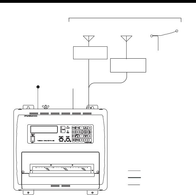
SYSTEM CONFIGURATION
|
|
Choose one |
|
WHIP ANTENNA |
WHIP ANTENNA WIRE ANTENNA |
|
(2.6 m) |
(6 m) |
|
PREAMP UNIT |
OR |
|
|
|
|
FAX-5 |
|
|
|
MATCHING BOX |
|
|
ARD-1 |
12-24 VDC |
External |
|
Receiver |
|
|
|
|
FACSIMILE RECEIVER
FAX-408
: Standard supply : Optional suppply : Local supply
viii

1.OPERATION
1.1Control Description
Control panel 
Paper cutter 
 Paper compartment cover
TIMER |
PRG FRQ |
1 |
2 |
3 |
|
TUNE |
|
|
|
|
|
RCD |
DIM |
CH |
4 |
5 |
6 |
POWER |
SPD |
REV |
7 |
8 |
9 |
VOLUME SYNC |
|||||
ON |
|
|
|
|
|
FACSIMILE RECEIVER FAX-408 |
IOC |
RCD |
C |
0 |
E |
OFF |
|
|
|
PAPER FEED |
|
|
|
|
|
||
|
|
|
|
|
Control description |
|
|
|
|
|
|
|
|
Control, |
Description |
||
|
|
indicator |
|
||
|
|
|
|
|
|
|
POWER |
|
|||
|
|
ON |
|
||
|
|
|
|
|
Turns power on and off. |
|
|
|
|
|
|
|
|
|
|
|
|
OFF
VOLUME
Adjusts volume of Rx signal and key beep.
SYNC
Fine tunes the phasing signal.
1

1. OPERATION
|
Control description (con’t from previous page) |
|
|
|
|
Control, |
Description |
|
indicator |
|
|
|
|
|
PRG |
• Enables a setting mode (in combination with numeric key). Press the key fol- |
|
lowed by appropriate numeric key to choose setting mode. |
||
|
||
|
1- Chooses internal or external receiver. |
|
|
2- Sets timer reception functions. |
|
|
3- Sets sleep timer. |
|
|
4- Adds or edit channels. |
|
|
5- Sets date and time. |
|
|
6- Sets ISB shift. |
|
|
7- Adjusts LCD contrast. |
|
|
9- Clears RAM. |
|
|
• Returns to top page in setting mode. |
|
|
|
|
FRQ |
• Changes from channel mode to frequency mode. |
|
• Sets frequency in frequency mode. |
||
|
||
|
|
|
DIM |
Adjust LCD brilliance and LED brightness, in five levels. |
|
|
|
|
CH |
• Changes from frequency mode to channel mode. |
|
• Sets channel in channel mode. |
||
|
||
|
|
|
SPD |
Chooses recording speed. |
|
|
|
|
REV |
• Reverses recording format (from black on white to white on black and vice |
|
versa). |
||
|
||
|
• Inserts decimal point when entering frequency, asterisk when entering channel. |
|
|
• Chooses + or -. |
|
|
|
|
IOC |
Chooses IOC (Index of Cooperation). |
|
|
|
|
RCD |
Starts and stops recording in manual recording. |
|
|
|
|
E |
Confirms setting. |
|
|
|
|
C |
• Clears data in setting mode. |
|
• Switches from setting mode to standby mode. |
||
|
||
|
|
|
2 |
Raises channel in channel mode, or raises frequency in frequency mode. |
|
|
|
|
4 |
Manual phasing (leftward) in recording. Each press shifts the recording leftward |
|
by about 5 mm. |
||
|
||
|
|
|
5 |
Displays date and time. |
|
|
|
|
6 |
Manual phasing (rightward) in recording. Each press shifts the recording right- |
|
ward by about 5 mm. |
||
|
||
|
|
|
8 |
Lowers channel in channel mode, or lowers frequency in frequency mode. |
|
|
|
|
0 |
Feeds paper. |
|
|
|
|
TUNE |
The top, middle or bottom LED lights when the receive frequency is higher, the |
|
same or lower than programmed frequency, respectively. |
||
|
||
|
|
|
TIMER |
Lights when the timer mode or sleep mode is active. |
|
|
||
|
|
|
RCD |
• Flashes when receiving start signal. |
|
• Lights when recording is in progress. |
||
|
2

1. OPERATION
1.2Turning the Power On/Off
Press the POWER key to turn the power on or off. When the power is applied, the last-used channel appears.
1.3Adjusting LCD Contrast
1.Press the PRG key.
2.Press the 7 key to show the contrast setting screen.
SET CONTRAST by S/T KEY
3.Press S or T key to adjust the contrast, in 10 levels (0-9). The chosen level is indicated on the LCD.
4.Press the E key.
5.Press the C key to return to the standby display.
1.4Adjusting LCD Brilliance and LED Brightness
Use the DIM key to adjust LCD brilliance and LED brightness, in five levels.
1.5Channel and Frequency Displays
The channel display may be chosen with the CH key; the frequency display with the FRQ key. The channel number is displayed in three digits. In the example below the channel number is 000.
|
|
|
CH No. |
|
Call Sign Frequency |
|
CH No. Call Sign |
Frequency |
|||||||||||
|
|
|
|
|
|
|
|
|
|
|
|
|
|
|
|
|
|
|
|
"C" denotes channel |
|
|
C000 |
JMH 3622.5 |
|
|
000 |
JMH |
F |
|
3622.5 |
|
|||||||
|
|
|
|
|
|||||||||||||||
display mode. |
S120 |
I576 |
|
S120 |
I576 |
|
|
|
|
|
|||||||||
|
|
|
|
|
|
||||||||||||||
|
|
|
|
|
|
|
|
|
|
|
|
|
|
|
|
|
|
||
|
|
|
|
|
|
|
|
|
|
|
|
|
|
|
|
|
|
|
|
|
|
|
|
|
|
|
|
|
|
|
|
|
|
|
|
||||
|
|
|
Speed |
IOC |
|
Speed IOC |
"F" denotes frequency |
||||||||||||
|
|
|
|
|
|
|
|
|
|
|
|
|
|
|
display mode. |
||||
|
|
|
Channel display |
|
|
Frequency display |
|||||||||||||
1.5.1Channel setting
In the channel display mode, press S or T key to choose channel number. A channel may also be selected manually by pressing the CH key when in the channel display mode and then entering channel number with the numeric keys. An asterisk (*) may be entered (with REV/z key) at the 3rd digit location to receive the most sensitive frequency of a channel group automatically.
3
1. OPERATION
1.5.2Selection of desired frequency, fine adjustment of frequency
Frequency may also be entered manually by pressing the FRQ key, and then entering frequency by using the numeric keys and the REV/z key (for entering decimal point). The available frequency range is 2000.0 - 24999.9 kHz.
In the frequency display mode, use the S or Tkey to fine tune a frequency when in the frequency display mode, in resolution of 0.1 kHz. When properly tuned, the center TUNE LED (green) lights. If the upper TUNE LED (red) is lit, use the S key, and if the lower TUNE LED (red) is lit, use the T key.
1.6Automatic Receiving
Once you choose the facsimile station from which to receive, the system goes into standby to await the start signal from the facsimile station. Recording starts when the start signal is received.
1. Press the CH key to show the channel display.
C00* |
JMH |
3622.5 |
* Asterisk indicates automatic |
S120 |
I576 |
|
frequency selection. |
|
|
||
|
|
|
|
2. Press the S or T key to choose channel desired.
Note: Alternatively, you may enter the frequency of the broadcasting station by pressing the FRQ key and entering frequency with the numeric keys and the REV/z key (for decimal point).
When the start signal is received, the message "AUTO START SEARCHING FRAME" appears and the RCD LED (orange) flashes. Speed and IOC are automatically adjusted when recording starts. The RCD LED lights during recording.
Note: The TUNE LED goes off when the RX level goes below a certain level or the equipment is not receiving. Even if the TUNE LED goes off, the equipment records the fax signal as long as the S/N ratio is suitable. Therefore, this is not a sign of TUNE LED trouble or equipment malfunction.
Stopping recording
Recording stops automatically when the stop signal is received. You may also stop the recording manually by pressing the RCD key. The RCD LED goes off when recording is stopped.
4

1. OPERATION
1.7Manual Receiving
This section shows you to manually receive a facsimile broadcast. For example, you may want to receive a facsimile broadcast already in progress or receive from a facsimile station that does not use start and stop signals.
1. Press the CH key to show the channel display.
C000 JMH 3622.5
S120 I576
2. Press the S or T key to choose channel desired.
Note: Alternatively, you may enter the frequency of the broadcasting station by pressing the FRQ key and entering frequency with the numeric keys and the REV/z key (for decimal point).
3. Press the RCD key to start receiving.
MANUAL START SEARCHING FRAME appears on the display and the RCD LED (orange) flashes.
4.If recording does not start after a while, press the RCD key again. The RCD LED stops flashing and lights when recording starts.
5.If necessary, use the SPD key and IOC keys to choose rotation speed and IOC, respectively, referring to paragraph 1.9.1.
Stopping recording
Recording stops automatically when the stop signal is received. To stop recording manually, press the RCD key. The RCD LED goes off when recording is stopped.
1.8Timer Receiving
Most facsimile stations transmit facsimile images in accordance with a schedule issued by relative meteorological observatory. (You can find facsimile schedules in the publication “Meteorological Facsimile Broadcasts,” available through meteorological observatory bodies.) If you wish to receive a certain facsimile broadcast on a regular basis, therefore, the timer mode will virtually allow you “hands-off” automatic operation. 16 timer programs may be set.
1.8.1Registering timer programs
1. Press the PRG key to display the setting mode.
|
|
[PRG] key |
|
|||||
C000 |
JMH 3622.5 |
|
|
|
|
|
SET PRG. No. 1-9 |
|
|
|
|
|
|
||||
S120 |
I576 |
|
|
|
|
|
ESC PUSH C KEY |
|
[C] key |
||||||||
|
|
|
||||||
|
Standby display |
Setting mode |
||||||
|
|
|
|
|
|
|||
2. Press the 2 key to show the timer reception setting mode.
TIMER RCV : 1-OFF 2-ON 3-RCL 4-STR
5

1. OPERATION
3. Press the 4 key to choose STR (Store).
STORE TIMER REG
SET REG No. 0-F
4.Use the S or T key to choose timer program number and press the E key. For example, choose “1” and the display then looks something like the one below.
R1 SET CHANNEL
No. in 3 FIGURES
5. Enter a channel number and press the E key.
R1 C000 SET DAY of THE WEEK by ST
6.Set the day of the week which to receive the program, using the S or T key. Choose the asterisk (*) to get a broadcast daily at the same time.
7.Press the E key.
R1 C000 MON
SET START/STOP
8.Set start and stop times, in 24-hour notation, using the numeric keys. (When registering programs which follow one another consecutively, the time between programs should be set at least one minute apart. For example, you have two programs to register, the first at 12:00-12:30 and the second at 12:30-13:00. In this case, set the time for the second program to 12:3113:00.)
9.Press the E key.
10.Press the C key.
1.8.2Choosing timer programs for timer reception
Choose timer programs to use in timer reception as follows:
1. Press the PRG key and the 2 key to show the timer reception setting mode.
TIMER RCV : 1-OFF 2-ON 3-RCL 4-STR
2. Press the 2 key to choose ON.
SET REG No. 0-F
PUSH S/T&X& E KEY
3. Use the S or T key to choose timer program number to activate, and press the X key.
TIMER RCV No.: 4 4
4.Repeat step 3 as necessary to choose other programs.
5.After choosing all programs necessary, press the E key.
The start and stop times of the earliest program are displayed. The TIMER LED (orange) lights when timer recording is enabled. Note that all keys except the PRG key are locked.
6
Loading...