


 Loading...
MARINE RADAR
MODEL MODEL 821/841

C
9 - 5 2 , A s h i h a r a - c h o , N i s h i n o m i y a , J a p a n
Tel ephone : |
0798 |
- 65 |
- 2 111 |
Tel efax : |
0798 |
- 65 |
- 420 0 |
Al l rights reserved . |
Printed in Japan |
|
PUB. No. OME-34160 |
(Y OS H) |
M O DE L 821/841 |
 You r Loc a l A gent/Deal e r
FIRST EDITION |
: |
AUG. |
1995 |
G |
: |
JAN . |
11 , 200 1 |
 SAFETY INFORMATION
Safety Arrangements
All known steps are taken in the design of this radar to ensure that electromagnetic radio frequency energy radiated by the equipment will not be a hazard to personnel. This is true if the following precautions are met.
• Each piece of equipment is grounded to an adequate grounding terminal or the ship or any mobile unit which carries the equipment. The grounding line should be as short as possible.
Can shock, burn or cause death.
Only qualified personnel should work inside the units of the radar.
Electrical Shock Hazard
This equipment contains high voltages which can cause severe injury or death. Any installation, internal adjustment, servicing and repair must be performed by qualified service personnel totally familiar with electrical circuits and servicing of the equipment.
!
!
Ground both the Display Unit and the Antenna Unit
Both the display unit and the antenna unit must be grounded. An ungrounded unit can cause electrical shock when its metallic parts are touched and receive or give off electromagnetic interference.
Useable Environment
This radar is designed and manufactured to be used on board marine vessels. Use in other environments may cause interference to other equipment.

TABLE OF CONTENTS
FOREWORD ..................................... |
ii |
||
SPECIFICATIONS ........................... |
iii |
||
EQUIPMENT LIST .......................... |
vii |
||
CONFIGURATION ......................... |
viii |
||
1. PRINCIPLE OF OPERATION ....... |
1 |
||
1.1 |
What is Radar? ..................................... |
1 |
|
1.2 |
How Ships Determined Position Before |
||
|
Radar .................................................... |
1 |
|
1.3 |
How Radar Determines Range ............ |
1 |
|
1.4 |
How Radar Determines Bearing .......... |
1 |
|
1.5 |
Radar Wave Speed and Antenna Rota- |
||
|
tion Speed ............................................. |
1 |
|
1.6 |
The Radar Display ............................... |
1 |
|
2. OPERATION |
|
||
2.1 |
Control Description ............................. |
3 |
|
2.2 |
Display Indications and Markers ......... |
4 |
|
2.3 Turning the Radar On and Off ............. |
4 |
||
2.4 |
Transmitting ......................................... |
5 |
|
2.5 |
Selecting the Range ............................. |
5 |
|
2.6 Adjusting LCD Backlighting and |
|
||
|
Display Tone ........................................ |
5 |
|
2.7 Adjusting Control Panel Brilliance ...... |
5 |
||
2.8 Adjusting GAIN, STC, A/C RAIN |
|
||
|
and FTC ............................................... |
6 |
|
2.9 |
Tuning the Receiver ............................. |
7 |
|
2.10 |
Measuring the Range ......................... |
8 |
|
2.11 Measuring the Bearing ....................... |
8 |
||
2.12 |
Menu Operation ................................. |
9 |
|
2.13 |
Selecting the Display Mode .............. |
11 |
|
2.14 The Window Display ....................... |
12 |
||
2.15 |
Selecting the Presentation Mode ..... |
12 |
|
2.16 |
Guard Alarm .................................... |
13 |
|
2.17 |
Suppressing Radar Interference ....... |
14 |
|
2.18 |
Suppressing Noise Interference ....... |
15 |
|
2.19 |
Selecting Pulselength ....................... |
15 |
|
2.20 |
Off Centering the Display ................ |
15 |
|
2.21 |
Echo Trails ....................................... |
16 |
|
2.22 The Navigation Data Display .......... |
16 |
||
2.23 |
Echo Stretch ..................................... |
17 |
|
2.24 |
Selecting Unit of Measurement |
|
|
|
|
for Range ......................................... |
18 |
2.25 |
Selecting Bearing Reference............ |
18 |
|
2.26 |
Watchman ........................................ |
18 |
2.27 |
Erasing the Heading Marker ............ |
19 |
2.28 |
Deselecting Ranges .......................... |
19 |
2.29 |
Displaying Navigation Data During |
|
|
Stand-by ........................................... |
19 |
2.30 |
Outputting Cursor Position to |
|
|
Navigator ......................................... |
20 |
2.31 |
Displaying Cursor Position, Range |
|
|
and Bearing to Cursor ...................... |
20 |
2.32 |
Visual Alarm Indications ................. |
20 |
3. INTERPRETING THE DISPLAY
3.1The Radar Wave and Radar Horizon . 21
3.2Target Properties and Radar Wave
|
Reflection ........................................... |
21 |
3.3 |
Range Resolution ............................... |
22 |
3.4 |
Bearing Resolution ............................ |
22 |
3.5 |
False Echoes ...................................... |
22 |
3.6 |
Nautical Chart and Radar Picture ...... |
24 |
4. MAINTENANCE & |
|
|
TROUBLESHOOTING |
|
|
4.1 |
Safety Information ............................. |
25 |
4.2 |
Preventative Maintenance .................. |
26 |
4.3 |
Replacing the Fuse ............................. |
26 |
4.4 Troubleshooting ................................. |
27 |
|
4.5 |
Self Test ............................................. |
28 |
5. INSTALLATION |
|
|
5.1 Antenna Unit Installation ................... |
29 |
|
5.2 |
Display Unit Installation .................... |
36 |
5.3 |
Installation Check List ....................... |
39 |
5.4 |
Initial Adjustment of Picture .............. |
40 |
5.5 |
Displaying the Installation Menus ..... |
40 |
5.6 |
Entering Initial Settings ..................... |
41 |
5.7 |
Relative Bearing Alignment .............. |
41 |
5.8 |
Sweep Timing .................................... |
42 |
5.9 |
Closing the Installation Menus .......... |
42 |
5.10 Signal cable connection ................... |
44 |
|
OUTLINE DRAWINGS .................. |
D-1 |
|
INTERCONNECTION |
|
|
DIAGRAMS ................................... |
S-1 |
|
SCHEMATIC DIAGRAMS ............. |
S-3 |
|
Declaration of Conformity |
|
|
i

FOREWORD
Congratulations on your choice of the FURUNO MODEL 821/MODEL 841 Marine Radar. We are confident you will see why the FURUNO name has become synonymous with quality and reliability.
For over 40 years FURUNO Electric Company has enjoyed an enviable reputation for innovative and dependable marine electronics equipment. This dedication to excellence is furthered by our extensive global network of agents and dealers.
Your radar is designed and constructed to meet the rigorous demands of the marine environment. However, no machine can perform its intended function unless properly installed and maintained. Please carefully read and follow the recommended procedures for installation, operation and maintenance.
While this unit can be installed by the purchaser, any purchaser who has doubts about his or her technical abilities may wish to have the unit installed by a FURUNO representative or other qualified technician. The importance of a thorough installation cannot be overemphasized.
We would appreciate hearing from you, the end-user, about whether we are achieving our purposes.
Thank you for considering and purchasing FURUNO equipment.
Features
Your radar has a large variety of functions, all contained in a remarkably small cabinet.
The main features of the MODEL 821/ MODEL 841 are:
•Traditional FURUNO reliability and quality in a compact, lightweight and low-cost radar.
•Smartly styled, light-weight and compact radome antenna fits even on small yachts.
•Durable brushless antenna motor.
•High definition 8" LCD raster-scan display.
•On-screen alphanumeric readout of all operational information.
•Standard features include EBL (Electronic Bearing Line), VRM (Variable Range Marker), Guard Alarm, Display Off Center and Echo Trail.
•Watchman feature periodically transmits the radar to check for radar targets which may be entering (or exiting) the alarm zone.
•Operates on 10.2 to 31.2 V DC power supply and consumes about 40 W.
•Ship’s position in latitude and longitude (or Loran C Time Differences), range and bearing to a waypoint, ship’s speed, heading and course can be shown in the bottom text area. (Requires a navigation aid which can output such data in NMEA 0183 format.)
•Zoom feature provided.
ii

SPECIFICATIONS– MODEL 821
Antenna Unit
1.Radiator
Printed array
2.Radiator length
40 cm
3.Horizontal beamwidth
5.7°
4.Vertical beamwidth
30˚
5.Sidelobe
Less than -20dB
6.Polarization
Horizontal
7.Antenna rotation speed
24 rpm
8.Wind resistance
Relative wind speed 100 kts (51.5 m/s)
Transceiver Module (contained in radome)
1.Transmitting tube
Magnetron E3587
2.Frequency
9410 MHz ±30MHz, P0N (X band)
3.Peak output power
2 kW
4.Pulselength & pulse repetition rate
0.12μs, 2100 Hz (0.25, 0.5, 0.75 nm)
0.3μs, 1200 Hz (1, 1.5, 2 nm) 0.8μs, 600 Hz (3, 4, 6, 8, 12, 24 nm)
5.Warm-up time
1:30
6.Modulator
FET switching method
7.I. F.
60 MHz
8.Tuning
Automatic or manual
9.Receiver front end
MIC (Microwave IC)
10.Bandwidth
7 MHz
11.Duplexer
Circulator with diode limiter
Display Unit
1.Indication system
PPI raster scan
2.Display
8-inch diagonal LCD, STN semitransparent, yellow mode
3.Range scales (nm)
Range, Ring Interval: 0.125(0.0625), 0.25(0.125), 0.5(0.125), 0.75(0.25), 1(0.25), 1.5(0.5), 2(0.5), 3(1), 4(1), 6(2), 8(2), 12(3), 16(4), 24(6)
4.Bearing resolution
6.2˚
5.Bearing accuracy
Better than 1˚
6.Range discrimination
Better than 25 m
7.Range ring accuracy & discrimination
0.9% or range in use or 8 m, whichever is larger
8.Minimum range
Better than 37 m
9.Markers
Heading marker, Bearing scale, Range ring, VRM, EBL, Waypoint (option), Tuning indicator, Alarm zone, Cursor
10.Alphanumeric indication
Standard: Electronic Bearing Line (EBL), Echo Stretch (ES), Rain Clutter Rejection (FTC), Alarm (G), Interference Rejection (IR), Stand-by (ST-BY), Echo Trail Time (TRAIL), Variable Range Marker
(VRM), Range, Range Ring Interval, Range and Bearing to Cursor (+), Off Center (OFF CENTER), Watchman (WATCHMAN)
iii

With navigation input (option): Course (CRS), Latitude and longitude, Speed (SPD), Range and bearing to waypoint (WP), Cross Track Error (XTE), Date and time, Water depth, Water temperature. (This radar has
only two data input ports. To receive data from more than two equipment install an mixing device.)
11. Vibration |
|
Vibration freq. |
Total amplitude |
5 to 12.5 Hz |
±1.6 mm |
12 to 25 Hz |
±0.35 mm |
25 to 50 Hz |
±0.10 mm |
12.Ambient Temperature
Antenna unit: –20˚C to +70˚C Display unit: 0˚C to +60˚C
Due to the inherent nature of the LCD its contrast may be affected under ambient temperature below 0˚C (32˚F) or above 50˚C (122˚F).
13.Humidity
Relative humidity 95% or less at +40˚C
14.Waterproofing
Display unit: IEC Pub no. 529 IPX5 Antenna unit: IEC Pub no. 945 class X
15.Power supply & power consumption
12 V or 24V(10.2 V to 31.2 V DC),
40 W approx.
16.Protection features
Protection against reverse polarity, overvoltage, overcurrent, and internal fault
17.Compass safe distance
Unit |
Standard |
Steering |
|
compass |
compass |
|
|
|
Display |
0.7 m |
0.5 m |
|
|
|
Antenna |
1.7 m |
1.4 m |
|
|
|
SPECIFICATIONS– MODEL 841
Antenna Unit
1.Radiator
Printed array
2.Radiator length
54 cm
3.Horizontal beamwidth
4°
4.Vertical beamwidth
25˚
5.Sidelobe
-20 dB within main lobe -23 dB outside main lobe
6.Polarization
Horizontal
7.Antenna rotation speed
24 rpm
8.Wind resistance
Relative wind speed 100 kts (51.5 m/s)
Transceiver Module (contained in radome)
1.Transmitting tube
Magnetron MG5248
2.Frequency
9410 MHz ±30MHz, P0N (X band)
3.Peak output power
4 kW
4.Pulselength & pulse repetition rate
0.08μs, 2100 Hz (0.25, 0.5, 0.75 nm) 0.3μs, 1200 Hz (1, 1.5, 2 nm)
0.8μs, 600 Hz (3, 4, 6, 8, 12, 24, 36 nm)
5.Warm-up time
2:30
6.Modulator switching method
FET
7.I. F.
60 MHz
8.Tuning
Automatic or manual
iv

9.Receiver front end
MIC (Michoeave IC)
10.Bandwidth
7 MHz
11.Duplexer
Circulator with diode limiter
Display Unit
1.Indication system
PPI raster scan
2.Display
8-inch diagonal LCD, STN semitransparent, yellow mode
3.Range scales (nm)
Range, Ring Interval: 0.125(0.0625), 0.25(0.125), 0.5(0.125), 0.75(0.25), 1(0.25), 1.5(0.5), 2(0.5), 3(1), 4(1), 6(2), 8(2), 12(3), 16(4), 24(6), 36 (6)
4.Bearing resolution
6.2˚
5.Bearing accuracy
Better than 1˚
6.Range discrimination
Better than 25 m
7.Range ring accuracy
& discrimination
0.9% or range in use or 8 m, whichever is larger
8.Minimum range
Better than 37 m
9.Markers
Heading marker, Bearing scale, Range ring, VRM, EBL, Waypoint (option), Tuning indicator, Alarm zone, Cursor
10.Alphanumeric indication
Standard: Electronic Bearing Line (EBL), Echo Stretch (ES), Rain Clutter Rejection (FTC), Alarm (G), Interference Rejection (IR), Stand-by (ST-BY), Echo Trail Time (TRAIL), Variable Range Marker
(VRM), Range, Range Ring Interval, Range and Bearing to Cursor (+), Off Center (OFF CENTER), Watchman (WATCHMAN)
With navigation input (option): Course (CRS), Latitude and longitude, Speed (SPD), Range and bearing to waypoint (WP), Cross Track Error (XTE), Date and time, Water depth, Water temperature. (This radar has only two data input ports. To receive data from more than two equipment install an mixing device.)
11. Vibration |
|
Vibration freq. |
Total amplitude |
5 to 12.5 Hz |
±1.6 mm |
12 to 25 Hz |
±0.35 mm |
25 to 50 Hz |
±0.10 mm |
12.Ambiont temperature
Antenna unit: –20˚C to +70˚C Display unit: 0˚C to +60˚C
Due to the inherent nature of the LCD its contrast may be affected under ambient temperature below 0˚C (32˚F) or above 50˚C (122˚F).
13.Humidity
Relative humidity 95% or less at +40˚C
14.Waterproofing
Display unit: IEC Pub no. 529 IPX5 Antenna unit: IEC Pub no. 945 class X
15.Power supply & power consumption
12 V or 24V(10.2 V to 31.2 V DC),
40 W approx.
16.Protection features
Protection against reverse polarity, overvoltage, overcurrent, and internal fault
Unit |
Standard |
Steering |
|
compass |
compass |
|
|
|
Display |
0.7 m |
0.5 m |
|
|
|
Antenna |
1.4 m |
1.1 m |
|
|
|
v

17. Compass safe distance
Interface NMEA
(MODEL 821/841)
Input
Own ship’s position : RMA>RMC>GLL (GLL is available Ver.5 and after.)
Speed : RMA>RMC>VTG>VHW
Heading(True):
HDT>VHW>HDG>VHW>HDM
Heading (Magnetic):
HDM>VHW>HDG>VHW>HDM
Course (True):
RMA>RMC>VTG
Course (Magnetic)
VTG>RMA>RMC
Waypoint (L/L, Range, Bearing):
RMB>BWC>BWR
Loran time difference :
RMA>GLC>GTD
Water depth : DPT>DBK, DBS, DBT
Water temperature : MDA>MTW
Time : ZDA
XTE : RMB>XTE>APB
Output
TLL : On using “HM OFF” key.
RSD : A cycle of four seconds
vi

CONFIGURATION OF
MODEL 821/841
Antenna Unit (MODEL 821)
|
MODEL 821/841 |
|
|
IEC 1162* |
(In/Out) |
Remote Display |
|
NAV |
|
||
Video Sounder IEC 1162* |
FMD-811 |
||
|
|||
|
(In) |
|
|
Fluxgate Heading |
|
|
|
Sensor C-2000 |
|
|
|
Gyro Gyro Converter |
External Alarm |
||
Buzzer OP03-136 |
|||
AD-100 |
|
||
|
|
||
*Equivalent to NMEA0183 |
|
Option |
5A |
Rectifier |
|
|
RP-62 |
10.2~31.2VDC |
115/230VAC |
viii

1. PRINCIPLE OF OPERATION
1.1 What is Radar?
The term "RADAR" is an acronym meaning RAdio Detection And Ranging. Although the basic principles of radar were developed during World War II, primarily by scientists in Great Britain and the United States, the use of echoes as an aid to navigation is not a new development.
1.4 How Radar Determines
Bearing
The bearing to a target found by the radar is determined by the direction in which the radar scanner antenna is pointing when it emits an electronic pulse and then receives a returning echo. Each time the scanner rotates pulses are transmitted in the full 360 degree circle, each pulse at a slightly different bearing from the previous one. Therefore, if one knows the direction in which the signal is sent out, one knows the direction from which the echo must return.
1.2 How Ships Determined
Position Before Radar
Before the invention of radar, when running in fog near a rugged shoreline, ships would sound a short blast on their whistles, fire a shot, or strike a bell. The time between the origination of the sound and the returning of the echo indicated how far the ship was from the cliffs or the shore. The direction from which the echo was heard indicated the relative bearing of the shore.
1.3 How Radar Determines
Range
Radar determines the distance to the target by calculating the time difference between the transmission of a radar signal and the reception of the reflected echo. It is a known fact that radar waves travel at a nearly constant speed of 162,000 nautical miles per second. Therefore the time required for a transmitted signal to travel to the target and return as an echo to the source is a measure of the distance to the target. Note that the echo makes a complete round trip, but only half the time of travel is needed to determine the one-way distance to the target. This radar automatically takes this into account in making the range calculation.
1.5 Radar Wave Speed and
Antenna Rotation Speed
Note that the speed of the radar waves out to the target and back again as echoes is extremely fast compared to the speed of rotation of the antenna. By the time radar echoes have returned to the scanner, the amount of scanner rotation after initial transmission of the radar pulse is extremely small.
1.6 The Radar Display
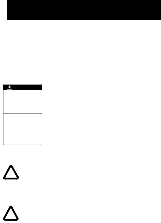
The range and bearing of a target is displayed on what is called a Plan Position Indicator (PPI). This display is essentially a polar diagram, with the transmitting ship’s position at the center. Images of target echoes are received and displayed at their relative bearings, and at their distance from the PPI center.
With a continuous display of the images of targets, the motion of the transmitting ship is also displayed.
1
Targets
A
 D A
D A
B
C B
Heading marker
|
Range and bearing |
|
of a target, relative |
|
to own ship, are |
D |
readable on the PPI. |
C
Own ship |
Own ship |
(radar) |
in center |
(A) Bird's eye view of situation |
(B) Radar picture of (A) |
Figure 1-1 How radar works
2
2. OPERATION
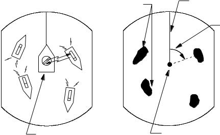
2.1 Control Description
Registers selection |
ENT |
MENU |
|
on menus. |
|
|
|
Press to adjust gain, |
ECHO |
HM |
|
OFF |
|||
A/C RAIN, STC |
|
||
|
|
||
and FTC. |
|
|
|
|
|
RANGE |
Cursor pad
Shift cursor, VRM and EBL; select items and options on menu.
Opens/closes menus.
Erases heading marker;
selects cursor data (Lat/Long, R/B); outputs cursor position.
Selects radar range.
Adjusts display |
TONE |
BRILL |
Adjusts display brilliance. |
|
tone. |
|
|
|
|
Turns the EBL |
EBL |
VRM |
Turns the VRM on/off. |
|
on/off. |
|
|
|
|
Plots targets' trails. |
TRAIL |
RINGS |
Turns the range |
|
|
|
|
rings on/off. |
|
Sets guard |
GUARD |
OFF |
Off centers |
|
CENTER |
||||
|
||||
zone area. |
|
|
the display. |
|
Selects display mode; |
DISP |
ST-BY |
Sets radar in stand-by; |
|
MODE |
||||
erases heading error |
TX |
transmits radar pulse. |
||
|
|
|||
indication. |
|
|
|
|
|
|
POWER |
Turns power on/off. |
Figure 2-1 Control panel
3

2.2 Display Indications and Markers
|
|
|
Heading (requires |
|
||
Range |
|
|
heading data) |
Echo trail, AUTO tuning |
||
|
|
|
|
TRAIL AUTO |
||
Range ring interval |
|
|
|
|
Echo trail elapsed time, |
|
0.5 |
|
HDG 326.8° |
|
0:00 15S |
||
Presentation mode |
1.5NM |
|
G (IN) |
echo trail time, tuning indicator |
||
CU |
|
|||||
Off center |
|
|
|
FTC1 |
Guard zone |
|
OFF |
|
|
|
ES |
||
Pulsewidth |
CENTER |
|
|
|
IR |
Fast Time Constant |
SP |
|
|
|
|||
|
|
|
|
|
|
(rain clutter suppressor) |
Heading marker |
|
|
|
|
|
Echo stretch |
|
|
|
|
|
Interference rejector |
|
|
|
|
|
|
|
|
Guard zone |
|
|
|
|
|
|
area |
|
|
|
|
|
|
|
|
|
|
|
|
Range ring |
Cursor |
|
|
|
|
|
|
EBL |
|
|
|
|
|
VRM |
|
|
VRM |
EBL |
+ CURSOR |
Range and bearing to cursor |
|
|
|
or cursor position in latitude |
||||
|
0.675NM 220.9°R 0.646NM 308.7°R |
} and longitude may be displayed |
||||
|
|
|
|
|
|
by pressing the [HM OFF] key. |
|
|
VRM |
EBL |
Cursor |
Cursor |
|
|
|
range |
bearing |
range |
bearing |
|
Figure 2-2 Display indications
2.3 Turning the Radar On and
Off
Turning the radar on
Press the [POWER] key to turn the radar on or off. The control panel lights and a timer displays the time remaining for warm up of the magnetron (the device which produces radar pulses), counting down from 2:30 (MODEL 841) or 1:30 (MODEL 821) to 0:01.
Note: When the power is reapplied within a certain amount of time and circuits remain charged, the warmup process is skipped—you can transmit immediately.
 CAUTION
The radar antenna emits high frequency radio radiation which can be harmful, particularly to your eyes. Never look directly at the antenna from a distance of less than two feet when the radar is in operation. Always make sure no one is near the antenna before turning on the radar.
Note: When the heading signal is lost, the HDG readout at the top of the screen shows ***.*. This warning stays on when the heading signal is restored to warn the operator that the readout may be unrealiable. The warning may be erased by pressing the [DISP MODE] key,
4
2.4 Transmitting
After the power is turned on and the magnetron has warmed up, ST-BY (Stand-By) appears at the screen center. This means the radar is now fully operational. In stand-by the radar is available for use at anytime— but no radar waves are being transmitted.
Press the [ST-BY TX] key to transmit. When transmitting, any echoes from targets appear on the display. This radar displays echoes in four tones of gray according to echo strength.
When you won’t be using the radar for an extended period but want to keep it in a state of readiness, press the [ST-BY TX] key to set the radar in stand-by.
2.5 Selecting the Range
2.6 Adjusting LCD Backlighting
and Display Tone
The [BRILL] key adjusts the LCD backlighting in eight levels, including off. The [TONE] key adjusts the tone (contrast) of the display in 32 levels, including off.
Procedure
1)Press the [BRILL] key (or [TONE] key). The display shown in Figure 2-3 appears.
|
|
BRILL |
|
|
|
UP |
|
|
TONE |
TONE |
Item selected |
|
DOWN |
UP |
|
|
for adjustment |
||
|
|
BRILL |
|
|
19 |
DOWN |
|
Tone |
7 |
LCD brilliance |
|
setting |
<MENU TO EXIT> |
setting |
|
The range selected automatically determines the range ring interval, the number of range rings, pulselength and pulse repetition rate, for optimal detection capability in short to long ranges.
Procedure
Press the [– RANGE +] key. The range and range ring interval appear at the top left corner on the display.
Tips for selecting the range
•When navigating in or around crowded harbors, select a short range to watch for possible collision situations.
•If you select a lower range while on open water, increase the range occasionally to watch for vessels that may be heading your way.
Figure 2-3 Display for adjustment of brilliance and tone
2)Press the [BRILL] key (or [TONE] key) to set level. For fine adjustment, press cursor pad at 12o'clock/6 o'clock for brilliance and 3o'clock/9o'clock for tone.
2.7 Adjusting Control Panel
Brilliance
Procedure
1)Press the [MENU] key.
2)Press the cursor pad to select Backlight/ Brilliance and press the [ENT] key.
3)Press the cursor pad to select Panel.
4)Press the cursor pad to select brilliance level; 4 is the highest.
5)Press the [ENT] key followed by the [MENU] key.
5

2.8 Adjusting GAIN, STC, A/C
RAIN and FTC
General procedure
The [ECHO] key enables adjustment of the gain, STC, A/C RAIN and FTC.
1)Press the [ECHO] key. The following display appears.
GAIN [MAUTANO 1 |
2 |
3 |
Item selected |
|
STC [MANAUTO 1 |
|
|
for adjustment |
|
2 |
3 |
|
||
A/C RAIN |
00 |
|
|
|
FTC |
0 1 2 |
|
|
|
12 |
|
|
|
Current |
|
|
|
level |
|
ECHO KEY
TO EXIT
Figure 2-4 Display for adjustment of GAIN, STC, A/C RAIN and FTC
2)Press the cursor pad to select item to adjust. Current selection is circumscribed by dashed rectangle.
3)Press [ENT].
3)Press the cursor pad to set level.
4)Press the [ECHO] key to finish.
How to adjust the gain (sensitivity)
The gain works in precisely the same manner as the volume control of a broadcast receiver, amplifying the signals received.
You can adjust the gain automatically or manually. For manual adjustment, adjust the sensitivity on the highest range—the background noise is clearer on that range. The proper setting is such that the background noise is just visible on the screen. If you set up for too little gain, weak echoes may be missed. On the contrary excessive gain yields too much background noise; strong targets may be missed because of the poor contrast between desired echoes and the background noise on the display.
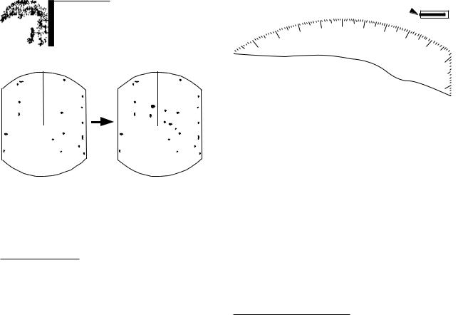
How to adjust STC (suppressing sea clutter)
Echoes from waves can be troublesome, covering the central part of the display with random signals known as sea clutter. The higher the waves, and the higher the scanner above the water, the further the clutter will extend. Sea clutter appears on the display as many small echoes which might affect radar performance. (See the left-hand figure in Figure 2-5).
The STC reduces the amplification of echoes at short ranges (where clutter is the greatest) and progressively increases amplification as the range increases, so amplification will be normal at those ranges where there is no sea clutter. The control is effective up to about 4 miles.
STC can be adjusted automatically or manually. For manual adjustment, first adjust the gain and then transmit on short range. Adjust the STC level such that the clutter is broken up into small dots, and small targets become distinguishable. If the setting is set too low, targets will be hidden in the clutter, while if it is set too high, both sea clutter and targets will disappear from the display. In most cases adjust so clutter has disappeared to leeward, but a little is still visible windward.
If there is no clutter visible on the display, turn off the circuit.
Sea clutter at |
STC adjusted; |
display center |
sea clutter suppressed. |
Figure 2-5 Effect of STC
6
How to adjust A/C RAIN and FTC (suppressing rain clutter)
The vertical beamwidth of the scanner is designed to see surface targets even when the ship is rolling. However, by this design the unit will also detect rain clutter (rain, snow, hail, etc.) in the same manner as normal targets. Figure 2-6 shows the appearance of rain clutter on the display.
Adjusting A/C RAIN
When rain clutter masks echoes over a wide range, raise the A/C RAIN slightly to distinguish targets from the clutter.
2.9 Tuning the Receiver
The receiver can be tuned automatically or manually. For automatic tuning the receiver is tuned each time you switch from standby to transmit. For manual tuning, the receiver is properly tuned when the longest tuning indicator appears. (However, the length of the indicator changes with the number of radar echoes, range and other factors.)
Tuning
indicator  AUTO
AUTO
1.5NM
0.5
Appearance of |
A/C RAIN adjusted; |
rain clutter |
rain clutter suppressed. |
Figure 2-6 Effect of A/C RAIN
Adjusting FTC
To suppress rain clutter from heavy storms or scattered rain clutter, adjust the FTC. The FTC circuit splits up these unwanted echoes into a speckled pattern, making recognition of solid targets easier. FTC and selected level appear at the top right-hand corner of the display when the circuit is turned on.
Note: In addition to reducing clutter, the FTC can be used in fine weather to clarify the picture when navigating in confined waters. However, with the circuit activated the receiver is less sensitive. Therefore, turn off the circuit when its function is not required.
Figure 2-7 Tuning indicator
Manual tuning
The default tuning method is automatic. To switch to manual tuning;
1)Press the [MENU] key to open the menu.
2)Press the cursor pad to select Tuning.
3)Press the cursor pad to select MANUAL.
4)Press the [ENT] key followed by the [MENU] key.
How to tune manually
While pressing and holding down the [HM OFF] key, press the 9 o'clock or 3o'clock position on the cursor pad to tune. Tune to show the longest tuning indicator.
7
2.10 Measuring the Range
You can measure the range to a target three ways: by the range rings, by the cursor, and by the VRM (Variable Range Marker).
By range rings
Press the [RINGS] key to display the range rings. Count the number of rings between the center of the display and the target. Check the range ring interval (at the top left corner) and judge the distance of the echo from the inner edge of the nearest ring.
By cursor
Operate the cursor pad to place the cursor intersection on the inside edge of the target echo. The range to the target, as well as the bearing, appears at the bottom of the display.
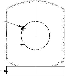
By VRM
1)Press the [VRM] key to display the VRM.
2)Press the cursor pad to place the VRM on the inside edge of the target. (The cursor appears and is linked with the VRM, allowing you to measure both range and bearing to the target.)
3)Check the VRM readout at the bottom left-hand corner of the display to find the range to the target.
Note: The VRM is automatically anchored when no cursor pad key is operated within about 10 seconds.
To erase the VRM, press and hold down the [VRM] key for about three seconds.
1.5NM
0.5
Target
VRM 
VRM |
VRM |
EBL |
+ CURSOR |
0.675NM 220.9°R |
0.675NM 308.7°R |
||
range |
|
|
|
Figure 2-8 Measuring range by the VRM
2.11 Measuring the Bearing
There are two ways to measure the bearing to a target: by the cursor, and by the EBL (Electronic Bearing Line).
By cursor
Operate the cursor pad to bisect the target with the cursor intersection. The bearing to the target appears at the bottom right-hand corner of the display.
By EBL
1)Press the [EBL] key to display the EBL.
2)Press the cursor pad to bisect the target with the EBL. (The cursor appears and is linked with the EBL, allowing you to measure both bearing and range to the target.)
3)Check the EBL readout at the bottom lefthand corner of the display to find the bearing to the target.
Note: The EBL is automatically anchored when no cursor pad key is operated within about 10 seconds.
8
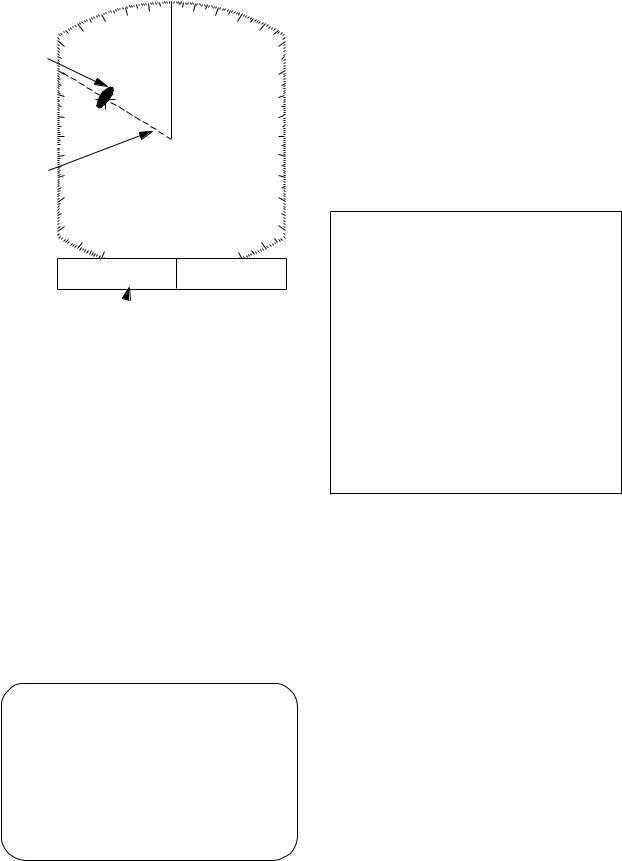
To erase the EBL, press and hold down the [EBL] key for about three seconds.
1.5NM
0.5
Target
EBL
VRM |
EBL |
+ CURSOR |
0.675 NM 300.1°R |
0.675NM 300.1°R |
|
 EBL bearing
Figure 2-9 Measuring bearing by the EBL
Tips for measuring the bearing
•Bearing measurements of smaller targets are more accurate; the center of larger target echoes is not as easily identified.
•Bearings of stationary or slower moving targets are more accurate than bearings of faster moving targets.
•To minimize bearing errors keep echoes in the outer half of the picture by changing the range scale; angular difference becomes difficult to resolve as a target approaches the center of the display.
Target on collision course with your vessel?
You can determine if a target might be on a collision course with your vessel by placing the EBL on the target. If it tracks along the EBL as it approaches the screen center it may be on a collision course with your vessel.
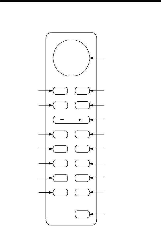
2.12 Menu Operation
The menu, consisting of 6 sub menus, mostly contains less-often used functions which once preset do not require regular adjustment. To open or close the menu, press the [MENU] key. You can select items on the menu with the cursor pad.
Basic menu operation
1)Press the [MENU] key to open the menu. The main menu appears.
● MAIN MENU ●
Select item by ▲▼ keys and press ENT key.
1.Backlight/Brilliance
2.P/L, IR, NR & Radar Mode
3.Nav Data
4.Mode & Function
5. Tuning |
AUTO |
MANUAL |
6.Self Check
7.Installation Setup 1
. . . . . . . . . . . . . . . . .
Press HM-OFF to temporarily hide menu.
<Press MENU key to escape.>
Figure 2-10 Main menu
2)Press the cursor pad to select menu and press the [ENT] key.
3)Press the cursor pad to select menu item.
4)Press the cursor pad to select option.
5)Press the [ENT] key to register selection.
6)Press the [MENU] key to close the menu.
Menu description
See the table on the next page.
9
Loading...