


 Loading...
PRIMERGY TX150 S3
Server System
Options Guide
Edition January 2005
Comments… Suggestions… Corrections…
The User Documentation Department would like to know your opinion of this manual. Your feedback helps us optimize our documentation to suit your individual needs.
Fax forms for sending us your comments are included in the back of the manual.
There you will also find the addresses of the relevant
User Documentation Department.
Certified documentation according to DIN EN ISO 9001:2000
To ensure a consistently high quality standard and user-friendliness, this documentation was created to meet the regulations of a quality management system which complies with the requirements of the standard DIN EN ISO 9001:2000.
cognitas. Gesellschaft für Technik-Dokumentation mbH www.cognitas.de
Copyright and Trademarks
Copyright © 2005 Fujitsu Siemens Computers GmbH.
All rights reserved.
Delivery subject to availability; right of technical modifications reserved.
All hardware and software names used are trademarks of their respective manufacturers.
This manual is printed on paper treated with chlorine-free bleach.

Introduction
Procedure
Safety notes
Preparation
Main memory
Accessible drives
Controller in the PCI slots
RemoteView components
External SCSI interface
Conversion standard PS to hot-plug PS
Continued 

Converting from the floorstand model to the rack model
Completion
Appendix
Abbreviations, Related publications and Index

Contents
1 |
Introduction . . . . . . . . . . . . . . . . . . . . . . . . . . . . |
1 |
1.1 |
Overview of the documentation . . . . . . . . . . . . . . . . . . |
1 |
1.2Extensions and conversions . . . . . . . . . . . . . . . . . . . . 2
1.3Notational conventions . . . . . . . . . . . . . . . . . . . . . . . 4
2Procedure . . . . . . . . . . . . . . . . . . . . . . . . . . . . . 5
3Safety notes . . . . . . . . . . . . . . . . . . . . . . . . . . . 7
4Preparation . . . . . . . . . . . . . . . . . . . . . . . . . . . 13
4.1 |
Floorstand model . . . . . . . . . . . . . . . . . . . . . . . . |
13 |
4.1.1 |
Opening the server . . . . . . . . . . . . . . . . . . . . . . . |
13 |
4.1.2 |
Removing the front cover . . . . . . . . . . . . . . . . . . . . |
14 |
4.1.3Removing the hard disk cover . . . . . . . . . . . . . . . . . . 15
4.2 |
Rack model . . . . . . . . . . . . . . . . . . . . . . . . . . . |
16 |
4.2.1 |
Opening the server . . . . . . . . . . . . . . . . . . . . . . . |
16 |
4.2.2Removing the rack front cover . . . . . . . . . . . . . . . . . . 19
5 |
Main memory . . . . . . . . . . . . . . . . . . . . . . . . . . |
21 |
5.1 |
Equipping rules . . . . . . . . . . . . . . . . . . . . . . . . . |
21 |
5.2 |
Extending/replacing the main memory . . . . . . . . . . . . . |
22 |
6 |
Accessible drives . . . . . . . . . . . . . . . . . . . . . . . |
25 |
6.1 |
Installing an accessible 5.25-inch drive . . . . . . . . . . . . . |
25 |
6.2 |
Installing the hard disks extension box . . . . . . . . . . . . . |
29 |
7 |
Controller in the PCI slots . . . . . . . . . . . . . . . . . . . |
31 |
7.1Installing a controller . . . . . . . . . . . . . . . . . . . . . . . 32
7.2 |
PCI slot assembling . . . . . . . . . . . . . . . . . . . . . . . |
34 |
8 |
RemoteView components . . . . . . . . . . . . . . . . . . . |
35 |
8.1 |
RemoteView Service Board S2 LP . . . . . . . . . . . . . . . |
35 |
9 |
External SCSI interface . . . . . . . . . . . . . . . . . . . . |
39 |
9.1 |
Installing the external SCSI interface . . . . . . . . . . . . . . |
39 |
10 |
Conversion standard PS to hot-plug PS . . . . . . . . . . . |
41 |
11Converting from the floorstand model to the rack model . . 53
12Completion . . . . . . . . . . . . . . . . . . . . . . . . . . . 59
12.1 |
Floorstand model . . . . . . . . . . . . . . . . . . . . . . . . 59 |
U41604-Z156-1-76 |
Options Guide |

Contents
12.1.1Attaching the hard disk cover . . . . . . . . . . . . . . . . . . . 59
12.1.2 |
Attaching the front cover . . . . . . . . . . . . . . . . . . . . . 60 |
12.1.3Closing the server . . . . . . . . . . . . . . . . . . . . . . . . . 61
12.2Rack model . . . . . . . . . . . . . . . . . . . . . . . . . . . . 62
12.2.1 |
Attaching the rack front cover . . . . . . . . . . . . . . . . . . 62 |
12.2.2Closing the server . . . . . . . . . . . . . . . . . . . . . . . . . 64
13 |
Appendix . . |
. . . . . . . . . . . . . . . . . . . . . . . . |
. |
. . 67 |
||||||||||||
13.1 |
Cabling . . |
. |
. . . . . . . . . . . . . . . . . . . . . . . . |
. |
. . 67 |
|||||||||||
13.1.1 |
SCSI version |
|
. |
. |
. |
. . . . . . . . . . . . |
. . |
. |
. . |
. |
. |
. |
. . . |
. 67 |
||
13.1.2 |
SATA version |
|
. |
. |
. |
. . . . . . . . . . . . |
. . |
. |
. . |
. |
. |
. |
. . . |
. 71 |
||
Abbreviations . . . . . . . . . . . . . . . . . . . . . . . . . . . . . . . . 73 Related publications . . . . . . . . . . . . . . . . . . . . . . . . . . . . 79 Index . . . . . . . . . . . . . . . . . . . . . . . . . . . . . . . . . . . . 81
Options Guide |
U41604-Z156-1-76 |

1 Introduction
The PRIMERGY TX150 S3 Server is an Intel-based server for medium-sized networks and large companies. The server is suitable for use as a file server as well as an application, information, or Internet server. It is available as a floorstand or rack model. The floorstand model can be converted to a rack model using an optional conversion kit.
1.1Overview of the documentation
IPRIMERGY manuals are available in PDF format on the ServerBooks CD which is supplied in the ServerView Suite package for every server system.
These PDF files can also be downloaded free of charge from the Internet: at http://manuals.fujitsu-siemens.com you will find an overview page with the online documentation available on the Internet. You can go to the PRIMERGY Server documentation by clicking on “intel based Servers”.
Concept and target groups
This Options Guide shows you how you can expand and upgrade the server.
IThe Operating Manual for the server describes how you install/remove the hot-plug components.
The activities described in this manual may only be performed by technicians, service personnel or technical specialists.
Additional documentation about the server
The PRIMERGY TX150 S3 documentation comprises the following additional manuals:
–The “Security” manual (printed copy always supplied with the server, and available as a PDF file on the ServerBooks CD supplied)
–The “Guarantee” manual (printed copy always supplied with the server, and available as a PDF file on the ServerBooks CD supplied)
–The Operating Manual for the PRIMERGY TX150 S3 (PDF available on the
ServerBooks CD supplied)
U41604-Z156-1-76 |
Options Guide |
1 |

Extensions and conversions |
Introduction |
–The Technical Manual for the system board D1979 (PDF available on the
ServerBooks CD supplied)
–The “BIOS Setup” manual (PDF available on the ServerBooks CD supplied)
–The “PRIMERGY ServerView Suite - ServerStart” manual (printed copy always supplied with the server, and available as PDF file on the ServerBooks CD supplied)
–The “Global Array Manager Client Software User’s Guide” (PDF available on the ServerBooks CD supplied)
–The “Integrated Mirroring User’s Guide” (PDF available on the ServerBooks CD supplied)
IYou can order a supplementary ServerBooks CD by sending an e-mail to the following address, quoting your server data:
Reklamat-PC-LOG@fujitsu-siemens.com
Further sources of information:
–Technical Manual on the relevant rack
–Manual on the monitor
–Manual on ServerView Server Management
–Manual on the RemoteView Remote Test and Diagnostics System
–Documentation on boards and drives
–Documentation on your operating system
–Information files on your operating system
(see also “Related publications” on page 79)
1.2Extensions and conversions
Extension of the main memory
The four slots for the main memory are suitable for DDR1 333/400 MHz (unbuffered) SDRAM memory modules. The organization in two memory banks, 1 and 2, permits rapid memory access with two-way interleaving.
If the memory modules are populated in pairs, each pair must consist of identical memory modules (2-way interleaved mode).
Additional SATA hard disk drives
In the SATA version four bays are available for SATA hard disk drives.
2 |
Options Guide |
U41604-Z156-1-76 |
Introduction |
Extensions and conversions |
Additional accessible drives
Three 5.25-inch bays are available for accessible drives. The top side bay is already occupied by a CD/DVD ROM drive.
Hard disks extension box
In the SCSI version the two lower 5.25-inch bays for accessible drives can be used to integrate a hard disks extension box.
The hard disks extension box enables up to three additional HDD modules to be integrated. Each HDD module can accommodate a SCSI hard disk drive with an SCA (Single Connector Attachment) interface and a height of at most 1 inch. The connection to the SCSI backplane is made without cables via the SCA interface. This makes it simple to plug in or pull out the HDD modules. If the server has a RAID controller and the corresponding RAID configuration, defective HDD modules can also be replaced while the system is operating.
Additional controllers in the PCI slots
The system board offers six PCI slots: 2 x PCI-X (64 Bit / 66 MHz), 3 x PCI (32 Bit / 33 MHz) and 1 x PCI-Express x1 slot.
The PCI slot 2 is prepared for Zero Channel RAID (ZCR).
RemoteView Service Board S2 LP
The RemoteView Service Board S2 LP (RSB S2 LP) is a PCI board with a completely independent system, i.e. it has its own operating system with Web server and SNMP agents and can optionally be equipped with an external power supply. The RSB S2 LP permits remote diagnosis for system analysis, remote system configuration and remote restart even in the event of operating system failure or hardware faults. It has its own LAN connection and its own COM port. All the functions of the RSB S2 LP are thus available either via a LAN or modem.
External SCSI interface
If the internal hard disks are connected via a PCI RAID controller, one channel of the on-board controller can also be made available for connecting a peripheral cabinet SX10 via an external SCSI interface.
U41604-Z156-1-76 |
Options Guide |
3 |
Notational conventions |
Introduction |
Conversion standard power supply to hot-plug power supply
The standard power supply can be replaced by a hot-plug power supply. The hot-plug power supply consists of two power supply modules.
If one power supply module fails, the other power supply module guarantees the unrestricted operation and the defective power supply module can be replaced be replaced while the system is operating (hot-plug).
Conversion of the floorstand model to a rack model
The floorstand model can optionally be converted so that the server can be integrated into the common rack systems.
1.3Notational conventions
The following notational conventions are used in this manual:
Text in italics |
indicates commands, menu items or software programs. |
„Quotation marks“ |
indicate names of chapters and terms that are being |
|
emphasized. |
|
|
Ê |
describes activities that must be performed in the order |
|
shown. |
|
|
VCAUTION! |
pay particular attention to texts marked with this symbol. |
Failure to observe this warning may endanger your life, |
|
|
destroy the system or lead to the loss of data. |
Iindicates additional information, notes and tips.
Table 1: Notational conventions
4 |
Options Guide |
U41604-Z156-1-76 |

2 Procedure
VCAUTION!
The actions described in these instructions should only be performed by technicians, service personnel or technical specialists. Equipment repairs should only be performed by authorized, qualified staff. Any unauthorized opening and improper repairs could expose the user to risks (electric shock, energy hazards, fire hazards) and could also damage the equipment. Please note that any unauthorized opening of the device will result in the invalidation of the warranty and exclusion from all liability.
ÊFirst of all please familiarize yourself with the safety instructions in the section chapter “Safety notes” on page 7 et seqq. .
ÊEnsure that all required manuals (see “Additional documentation about the server” on page 1) are available, printing out the PDF files if necessary. You will definitely need the Operating Manual for the server and the Technical Manual for the system board.
ÊShut down the server correctly, switch it off, pull out the power plug(s), and open the server as described in the chapter “Preparation” on page 13 et seqq. .
ÊExtend or upgrade your server as described in the relevant chapter.
IThe Operating Manual for the server describes how you install/remove the hot-plug components.
IProcedures which are identical for the floorstand and rack models are only described for the floorstand model.
ÊClose the server, connect it to the power outlet, and switch it on as described in the chapter “Completion” on page 59 et seqq. .
ÊStart the operating system and, if necessary, configure it as required (see the Operating Manual).
U41604-Z156-1-76 |
Options Guide |
5 |

3 Safety notes
IThe following safety notes are also provided in the “Safety” manual.
This device complies with the relevant safety regulations for data processing equipment.
If you have any questions about where you can set up the device, contact your sales outlet or our customer service team.
VCAUTION!
The actions described in these instructions should only be performed by technicians, service personnel or technical specialists. Equipment repairs should only be performed by authorized, qualified staff. Any unauthorized openings and improper repairs could expose the user to risks (electric shock, energy hazards, fire hazards) and could also damage the equipment. Please note that any unauthorized openings of the device will result in the invalidation of the warranty and exclusion from all liability.
Before operating the device
VCAUTION!
●During installation and before operating the device, observe the instructions on environmental conditions for your device.
●If the device is brought in from a cold environment, condensation may form both inside and on the outside of the machine.
Wait until the device has acclimatized to room temperature and is absolutely dry before starting it up. Material damage may be caused to the device if this requirement is not observed.
●Transport the device only in the original packaging or in packaging that protects it from knocks and jolts.
U41604-Z156-1-76 |
Options Guide |
7 |

Safety notes
Installation and operation
VCAUTION!
●If the rack model is integrated in an installation that receives power from an industrial (public) power supply network with the IEC309 connector, the (public) power supply protection must comply with the requirements for the non-industrial (public) power supply networks for the type A connector.
●The server automatically sets itself to a voltage in the range of
100 V to 240 V. Make sure that your local voltage is within this range.
●This device has a specially approved power cable and must only be connected to a grounded insulated socket.
●Ensure that the power socket on the device or the grounded wall outlet is freely accessible.
●The ON/OFF button does not disconnect the device from the mains voltage. To disconnect the line voltage completely, remove the power plug(s) from the grounded insulated socket(s).
VCAUTION!
●Always connect the device and the attached peripherals to the same power circuit. Otherwise you run the risk of losing data if, for example, the central processing unit is still running but the peripheral device (e.g. storage subsystem) has failed during a power outage.
●Data cables to peripheral devices must be adequately shielded.
●To the LAN wiring the requirements apply in accordance with the standards EN 50173 and EN 50174-1/2. As minimum requirement the use of a protected LAN line of category 5 for 10/100 MBps Ethernet, and/or of category 5e for Gigabit Ethernet is considered. The requirements of the specification ISO/IEC 11801 are to be considered.
●Route the cables in such a way that they do not form a potential hazard (make sure no-one can trip over them) and that they cannot be damaged. When connecting up a device, refer to the relevant notes in this manual.
●Never connect or disconnect data transmission lines during a storm (lightning hazard).
8 |
Options Guide |
U41604-Z156-1-76 |

Safety notes
●In emergencies (e.g. damaged casing, controls or cables, penetration of liquids or foreign matter), switch off the device immediately, remove the power plug and contact your sales outlet or customer service team.
●Proper operation of the device (in accordance with IEC 60950/
EN 60950) is only ensured if the casing is completely assembled and the rear covers for the installation openings have been put in place (electric shock, cooling, fire protection, interference suppression).
●Only install system expansions that satisfy the requirements and rules governing safety and electromagnetic compatibility and relating to telecommunications terminal equipment. If you install other expansions, you may damage the system or violate the safety regulations and regulations governing RFI suppression. Information on which system expansions are suitable can be obtained from the customer service centre or your sales outlet.
VCAUTION!
●The components or parts marked with a warning label (e.g. lightning symbol) may only be opened, removed or exchanged by authorized, qualified personnel. The hot-plug power supply units are exceptions to this rule.
●The warranty expires if the device is damaged during the installation or replacement of system expansions.
●You may only set those resolutions and refresh rates specified in the „Technical data“ section of the monitor description. Otherwise, you may damage your monitor. If you are in any doubt, contact your sales outlet or customer service centre.
U41604-Z156-1-76 |
Options Guide |
9 |

Safety notes
Batteries
VCAUTION!
●Incorrect replacement of batteries may lead to a risk of explosion. The batteries may only be replaced with identical batteries or with a type recommended by the manufacturer (see the technical manual for the system board under “Related publications” on page 79).
●Do not throw batteries into the trash can. They must be disposed of in accordance with local regulations concerning special waste.
●The battery must be disposed of in accordance with local regulations concerning special waste.
●Replace the lithium battery on the system board in accordance with the instructions in the technical manual for the system board (see “Related publications” on page 79).
●All batteries containing pollutants are marked with a symbol (a crossed-out garbage can). In addition, the marking is provided with the chemical symbol of the heavy metal decisive for the classification as a pollutant:
Cd Cadmium Hg Mercury Pb Lead
10 |
Options Guide |
U41604-Z156-1-76 |

Safety notes
Notes on handling CDs and CD-/DVD-ROM drives
VCAUTION!
●Use only CDs in proper condition in the CD-/DVD-ROM drive of your server to prevent data loss, damage to the device and injuries.
●Therefore, check each CD for damage, cracks, breakage etc. before inserting it in the drive.
Please note that any additional labels applied may change the mechanical properties of a CD and cause imbalance.
Damaged and imbalanced CDs can break at high drive speeds (data loss).
Under certain conditions sharp-edged pieces of broken CDs can penetrate the cover of the drive (damage to the device) and be thrown out of the device (danger of injury, particularly on uncovered body parts such as the face or neck).
IYou protect the CD-/DVD-ROM drive and prevent mechanical damage, as well as premature wearing of the CDs, by observing the following suggestions:
–Only insert the CDs in the drive when needed and remove them after use.
–Store the CDs in suitable sleeves.
–Protect the CDs from exposure to heat and direct sunlight.
Note about the laser
The CD-/DVD-ROM drive is classified for laser class 1according to IEC 60825-1.
VCAUTION!
The CD-/DVD-ROM drive contains a laser diode (LED). Sometimes the LED produces a stronger laser beam than laser class 1. Direct view into this laser beam is dangerous.
Never remove parts of the CD-/DVD-ROM drive assembly!
U41604-Z156-1-76 |
Options Guide |
11 |

Safety notes
Modules with electrostatic-sensitive components:
Systems and components that might be damaged by electrostatic discharge (ESD) are marked with the following label:
Figure 1: ESD label
When you handle components fitted with ESDs, you must observe the following points under all circumstances:
●Remove the power plug from the power socket before inserting or removing components containing ESDs.
●You must always discharge yourself of static charges (e.g. by touching a grounded object) before working.
●The equipment and tools you use must be free of static charges.
●Only touch the components at the positions highlighted in green (touch points).
●Do not touch any exposed pins or conductors on a component.
●Use a grounding cable designed for this purpose to connect yourself to the system unit as you install components.
●Place all components on a static-safe base.
IYou will find a detailed description for handling ESD components in the relevant European or international standards (DIN EN 61340-5-1, ANSI/ESD S20.20).
12 |
Options Guide |
U41604-Z156-1-76 |
4 Preparation
VCAUTION!
Observe the safety instructions in the chapter “Safety notes” on page 7 et seqq. .
4.1Floorstand model
4.1.1Opening the server
ÊTerminate all applications and shut down the server correctly.
ÊIf your operating system has not switched off the sever, press the on/off switch.
ÊPull all power connectors out of the power outlets.
ÊIf required, remove the lock on the side cover.
1 |
4 |
3 |
2 |
Figure 2: Loosening the screws
ÊUnlock the server (1).
ÊLoosen the two screws at the rear side (2).
ÊPush back the left-hand side cover approxiate 2 cm (3).
ÊRemove the left-hand side cover (4).
U41604-Z156-1-76 |
Options Guide |
13 |
Floorstand model |
Preparation |
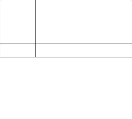
4.1.2Removing the front cover
Remove the front cover when making the following extensions and upgrades:
–Installing further accessible drives
–Upgrading the floorstand model to a rack model
Ê Remove the hard disk cover as shown in figure 5 on page 15.
 2
2
1
Figure 3: Removing the front cover
ÊDisengage the three tabs (1) on the left side one after the other and rotate the front cover outward (2) about 2 cm.
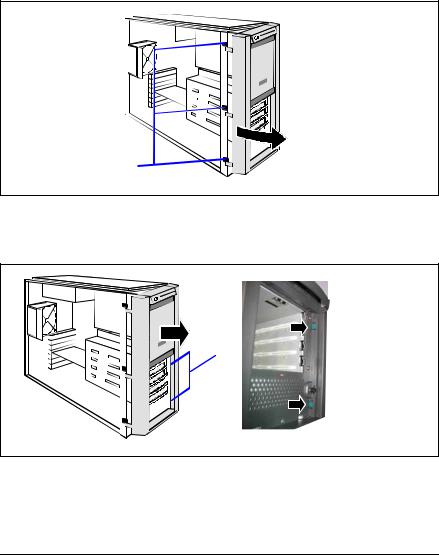
 2
2
1
Figure 4: Removing the front cover
ÊPress the two hooks (1) on the right side inward and pull out the front cover frontward (2).
14 |
Options Guide |
U41604-Z156-1-76 |
Preparation |
Floorstand model |
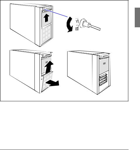
4.1.3Removing the hard disk cover
Remove the hard disk cover when making the following extensions and upgrades:
– Installing further SATA hard disk drives
ÊTerminate all applications and shut down the server correctly.
ÊIf your operating system has not switched off the sever, press the on/off switch.
2 |
1 |
4 |
3 |
Figure 5: Removing the hard disk cover
ÊUnlock the server (1) and remove the key.
ÊPush the drive cover up as far as possible (2).
ÊRemove the hard disk cover (3 + 4).
U41604-Z156-1-76 |
Options Guide |
15 |
Rack model |
Preparation |
4.2Rack model
ÊTerminate all applications and shut down the server correctly.
ÊIf your operating system has not switched off the server, press the on/off button.
ÊPull all power connectors out of the power outlets.
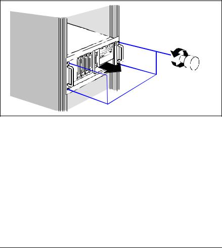
4.2.1Opening the server
1 |
2 |
Figure 6: Loosening the knurled screws
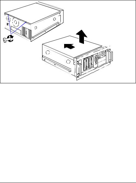
ÊLoosen the four knurled screws (1) and pull the server as far as possible out of the rack (2).
16 |
Options Guide |
U41604-Z156-1-76 |

Preparation |
Rack model |
|
2 |
|
1 |
Figure 7: Loosening the locking spring
ÊPress in the locking spring (1) on both sides and carefully pull the server outward (2).
2 |
Figure 8: Removing the server from the rack cabinet
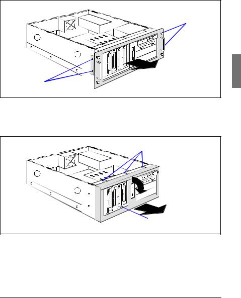
ÊDisconnect all cables on the rear of the server.
ÊRemove the telescopic rails on the left and right side (three screws).
U41604-Z156-1-76 |
Options Guide |
17 |
Rack model |
Preparation |
VCAUTION!
At least two people are needed to lift the server out of the rack cabinet.
Ê Lift the server out of the rails and place it on a table, for example.
|
3 |
1 |
2 |
|
2 |
Figure 9: Loosening the screws
ÊUnlock the top cover by removing the two screws at the rear side (1).
ÊPush back the top cover approxiate 2 cm (2).
ÊRemove the top cover (3).
18 |
Options Guide |
U41604-Z156-1-76 |
Preparation |
Rack model |
4.2.2Removing the rack front cover
Remove the rack front cover when carrying out the following extension:
– Installing further accessible drives
1
2
1
Figure 10: Removing the rack front cover
ÊRemove two screws on either side (1).
ÊRemove the rack front cover to the front (2).
1

 2
2
4

 3
3
Figure 11: Removing the plastic front cover
ÊDisengage the three tabs (1) on the top side one after the other and pull out the plastic front cover frontward (2) about 2 cm.
ÊPress the two hooks (3) on the bottom side downward and pull out the plastic front cover frontward (4).
U41604-Z156-1-76 |
Options Guide |
19 |
5 Main memory
VCAUTION!
Observe the safety instructions in the chapter “Safety notes” on page 7 et seqq. .
The system board supports up to 4 Gbytes of main memory. Four slots (2 slots form a memory bank) are provided for the main memory. Each memory bank can be equipped with 256 Mbyte, 512 Mbyte or 1 Gbyte unbuffered DDR I memory modules.
5.1Equipping rules
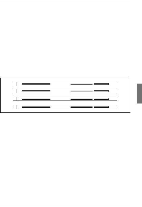
DIMM 1A
DIMM 2A
DIMM 1B
DIMM 2B
Figure 12: Structure of the main memory in memory banks and memory modules
–Each memory bank is equipped with two memory modules with the same capacity. Memory access takes place in 2-way interleaved mode.
–The memory module capacity can differ for the various memory banks: e.g. memory bank 2A/2B can be equipped with two 512 Mbyte memory modules, and memory bank 1A/1B with two 1 Gbyte memory modules.
U41604-Z156-1-76 |
Options Guide |
21 |
Loading...