


OWNER’S GUIDE
GLHV30T4KC - GLHV30T4KW GLHV36T5KC - GLHV36T5KW
READ AND SAVE THESE INSTRUCTIONS
Contents |
|
Product Registration .................................................................................... |
2 |
Important Safety Instructions ..................................................................... |
3 |
Installation ................................................................................................ |
4-6 |
Use and Care ................................................................................................ |
7 |
Hood Cleaning ............................................................................................. |
8 |
Lights Replacement ..................................................................................... |
8 |
Warranty..................................................................................................... |
10 |
Range Hood
P/N 316 137 203
LI1NTA
Product Registration
Register your Product
The self-addressed PRODUCT REGISTRATION CARD should be filled in completely, signed and returned to the Frigidaire Canada.
Thank you for choosing this appliance. The information contained within this Owner’s Guide will instruct you on how to properly operate and care for your range hood. Please read through the information contained in your literature pack to learn more about your new appliance.
Record Your Model and Serial Numbers
Record in the space provided below the model and serial numbers found on the serial plate located on the right hand side of the range hood.
Model Number: ___________________________________________________
Serial Number: ___________________________________________________
Date of Purchase: _________________________________________________
This Owner’s Guide contains general operatinginstructionsforyourrange hood and feature information for several models. Your range hood may not have all the described features.
Note: The instructions appearing in this Owner’s Guide are not meant to cover every possible condition and situation that may occur. Common sense and caution must be practiced when installing, operating and maintaining any appliance.
2
Important Safety Instructions
READ AND SAVE THESE INSTRUCTIONS
Take care when using cleaning agents or detergents.
Suitable for use in household cooking area
CAUTION - To reduce risk of fire and to properly exhaust air, be sure to duct air outside – Do not vent exhaust air into spaces within walls or ceilings or into attics, crawl spaces, or garages.
CAUTION - For General Ventilating Use Only. Do Not Use To Exhaust Hazardous Or Explosive Materials And Vapors.
WARNING – TO REDUCE THE RISK OF FIRE, ELECTRIC SHOCK, OR INJURY TO PERSONS, OBSERVE THE FOLLOWING:
a.Use this unit only in the manner intended by the manufacturer. If you have questions, contact the manufacturer.
b.Before servicing or cleaning unit, switch power off at service panel and lock the service disconnecting means to prevent power from being switched on accidentally. When the service disconnecting means cannot be locked, securely fasten a prominent warning device, such as a tag, to the service panel.
WARNING – TO REDUCE THE RISK OF A RANGE TOP GREASE FIRE:
a.Never leave surface units unattended at high settings. Boilovers cause smoking and greasy spillovers that may ignite. Heat oils slowly on low or medium settings.
b.Always turn hood ON when cooking at high heat or when cooking flaming foods.
c.Clean ventilating fans frequently. Grease should not be allowed to accumulate on fan or filter.
d.Use proper pan size. Always use cookware appropriate for the size of the surface element.
WARNING – TO REDUCE THE RISK OF INJURY TO PERSONS IN THE EVENT OF A RANGE TOP GREASE FIRE, OBSERVE THE FOLLOWING:
a.SMOTHER FLAMES with a close-fitting lid, cookie sheet, or metal tray, then turn off the burner. BE CAREFUL TO PREVENT BURNS. If the flames do not go out immediately, EVACUATE AND CALL THE FIRE DEPARTMENT.
b.NEVER PICK UP A FLAMING PAN – You may be burned.
c.DO NOT USE WATER, including wet dishcloths or towels – a violent steam explosion will result.
d.Use an extinguisher ONLY if:
1.You know you have a Class ABC extinguisher, and you already know how to operate it.
2.The fire is small and contained in the area where it started.
3.The fire department is being called.
4.You can fight the fire with your back to an exit.
WARNING – TO REDUCE THE RISK OF FIRE, ELECTRIC SHOCK, OR INJURY TO PERSONS, OBSERVE THE FOLLOWING:
a)Installation work and electrical wiring must be done by qualified person(s) in accordance with all applicable codes and standards, including fire-rated construction.
b)Sufficient air is needed for proper combustion and exhausting of gases through the flue (chimney) of fuel burning equipment to prevent back drafting. Follow the heating equipment manufacturer’s guideline and safety standards such as those published by the National Fire Protection Association (NFPA), and the American Society for Heating, Refrigeration and Air Conditioning Engineers (ASHRAE), and the local code authorities.
c)When cutting or drilling into wall or ceiling, do not damage electrical wiring and other hidden utilities.
d)Ducted fans must always be vented to the outdoors.
WARNING - TO REDUCE THE RISK OF FIRE, USE ONLY METAL DUCTWORK.
 WARNING
Electrical Shock Hazard - Can result in serious injury or death. Disconnect appliance from electric power before servicing.
If equipped, the fluorescent light bulb contains small amounts of mercury which must be recycled or disposed of according to Local, State, and Federal Codes.
3
Installation
FOR RESIDENTIAL USE ONLY
NOT TO BE INSTALLED OVER GAS GRILLS
PLEASE READ ENTIRE INSTRUCTIONS BEFORE PROCEEDING. INSTALLATION MUST COMPLY WITH ALL LOCAL CODES.
IMPORTANT: Save these Instructions for the Local Electrical Inspector’s use. INSTALLER: Please leave these Instructions with this unit for the owner.
OWNER: Please retain these instructions for future reference. Safety Warning: Turn off power circuit at the service entrance and lock out
panel, before wiring this appliance. Requirement: 120 V AC, 60 Hz. 15 or 20 A
Weight: 30” Model 34 lbs - 36” Model 38,5 lbs
Diameter of Transition 4” 3/4
Diameter of exhaust Duct required 4” 3/4
Considerations before installing Hood
1.For the most efficient air flow exhaust, use a straight run or as few elbows as possible.
CAUTION: Vent unit to outside of building, only.
2.If allowed in your area, use metallic flex ducting only to connect rigid duct directly to transitions.
3.COLD WEATHER installations should have an additional backdraft damper installed to minimize backward cold air flow and a nonmetallic thermal break to minimize conduction of outside temperatures as part of the ductwork. The damper should be on the cold air side of the thermal break. The break should be as close as possible to where the ducting enters the heated portion of the house.
4.Hood installation height above cooktop is the users preference. The lower the hood above the cooktop, the more efficient the capturing of cooking odors, grease and smoke. We recommends the hood be installed 18,5” minimum above an electric cooktop or 25,6” minimum above a gas cooktop . Be sure that your hood model fits your installation.
4
Installation
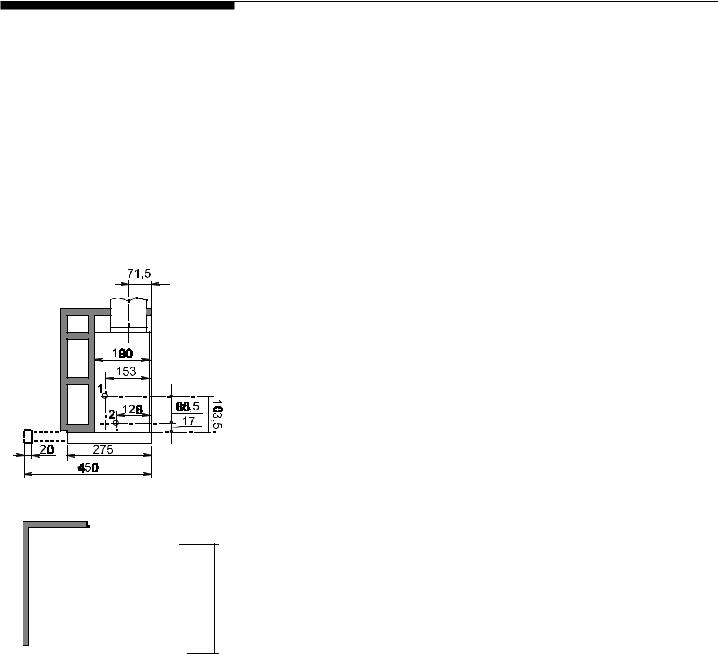
Figure 2
Figure 3
Pre-Installation consideration
The hood can be installed to be used in the following ways:
•External exhausting version
•Recycling version (with carbon filter to be ordered from your supplier)
External Exhausting Version
The air is expelled outside by means of a pipe to be connected to the coupling ring B (Figure 2).
In horizontal runs, the duct must be slightly slanted (about 10°) and directed upwards to vent the air easily from the room to the outside.
A non-return smoke valve is supplied as an optional to be mounted on the coupling flange .
Recycling version
The air is filtered through a carbon filter and recycled into the room.
If the hood has no filter ask for one from the technical assistance service or the manufacturing company, specifying the hood model.
To install the filter, insert it in the place provided and use the two hooks D to fasten it (Figure 4).
The filtered air is discharged above the wall cabinet through the baffle E, to be fastened by means of two screws provided directly on the vertical of the outlethole of the hood (if necessary fit a duct Ø120mm from the coupling flange to the upper edge of the hole provided on the top side of the cupboard (Figure 3).
5

Installation |
Figure 5 |
F |
Figure 6 |
M |
P |
Figure 7 |
Fastening the hood to the wall cabinet
Fit the drilling template, which comes with the hood, on the inner right side of the cabinet making sure side “A” coincides with back part.
Make at least two 2 mm. diameter holes at points 1-2 (Figure 5). Perform the same operations on the inner left side.
Use screws F (4.5x16) to fasten the hood to the cabinet (Figure 6). Attention! While mounting the hood on the wall cabinet be sure once the hood has been fastened, to allow the wiring compartment to be easily and safely reachable, in order to make eventual safety inspections and/or maintenance operations.
Box adjustment
The hood can be installed in cabinets with different depths; the front of the box must always be in line with the cabinet.
For alignment, adjust the back stops of the box.
For box adjustment, loosen screws M, slide the square plates P as necessary, and tighten screws M (Figure 7).
Ensure that the drawer, when fully retracted, turns OFF all power by acting positively on the rear microswitch.
Wiring to Power Supply
WARNING!
ELECTRICAL GROUNDING INSTRUCTIONS
THIS APPLIANCE IS FITTED WITH AN ELECTRICAL JUNCTION BOX WITH 3 WIRES, ONE OF WHICH (GREEN/YELLOW) SERVES TO GROUND THE APPLIANCE. TO PROTECT YOU AGAINST ELECTRIC SHOCK, THE GREEN AND YELLOW WIRE MUST BE CONNECTED TO THE GROUNDING WIRE IN YOUR
HOME ELECTRICAL SYSTEM, AND IT MUST UNDER NO CIRCUMSTANCES BE CUT OR REMOVED.
Warning: Turn off power circuit at the service panel before wiring this unit. 120 VAC, 15 or 20 Amp circuit required.
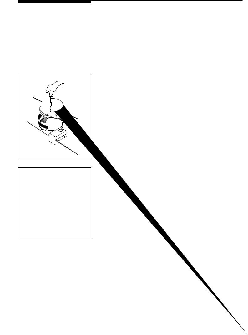
a.Remove j-box cover as shown in Figure 8.
b.Remove the knockout and install the strain relief (conduit) connector (1/ 2") in junction box.
c.Run 3 wires; black, white and green (#16 AWG) in 1/2" conduit from service panel to junction box.
d. Connect black wire from service panel to black or red in junction box, white to white and green to green-yellow. See Figure 8.
e. Close junction box cover, check all light bulbs to make sure they are secure in their sockets, then turn power on in service panel and check lights and blower operation per Care & Use section of this manual and install filters.
f. Make sure to leave this manual for the home owner.
Figure 8
6
 Loading...