


Friedrich YM18N34, SS12N10, SQ06N10, ES12N33, SS10N10 User Manual
...Service Manual
Room Air Conditioners
AUTO |
|
AUTO |
°F °C |
CONTINUOUS |
|
AUTO |
|
SYSTEM |
FAN MODE |
SCHEDULE |
FAN SPEED |
Standard Chassis R-410A Models
Cool Only
115-Volt: SS08M10, SS10M10, SS12M10, SS14M10
208-230-Volt: SS12M30, SS15M30, SM18M30, SM21M30
SM24M30, SL28M30, SL36M30
Cool with Electric Heat
208-230-Volt: ES12M33, ES15M33, EM18M34, EM24M35, EL36M35
Heat Pump with Electric Heat 208-230-Volt: YS12M33, YM18M34, YL24M35
Heat Pump
115-Volt: YS10M10
Kuhl-ServMan (5-10)
Table Of Contents |
|
Important Safety Information ..................................................................................................................................... |
2-4 |
Introduction ................................................................................................................................................................... |
5 |
Model and Serial Number Location .............................................................................................................................. |
5 |
Unit Identification .......................................................................................................................................................... |
6 |
Performance Data and Specifications .......................................................................................................................... |
7 |
Installation Information/Sleeve Dimensions/Circuit Rating ........................................................................................... |
8 |
Electrical Data ............................................................................................................................................................... |
9 |
Before Operating the Unit ............................................................................................................................................ |
10 |
Control Panel Operation .............................................................................................................................................. |
11 |
Alerts ...................................................................................................................................................................... |
12-14 |
Remote Control Operation ...................................................................................................................................... |
15-16 |
Electronic Control System Maintenance Operation ................................................................................................. |
17-20 |
Unit Operation .............................................................................................................................................................. |
21 |
Cool-Heat Set Points .................................................................................................................................................. |
22 |
Electronic Control Sequence of Operation ............................................................................................................ |
23-29 |
Unit Operation with a Wall-Stat ................................................................................................................................... |
29 |
Removing the Front Cover and Unit Chassis ................................................................................................................ |
30 |
Replacing the ID Coil Thermistor ................................................................................................................................ |
31 |
Replacing the Control Board ....................................................................................................................................... |
31 |
Low Voltage Interface Connector ................................................................................................................................ |
32 |
Replacing the ID Coil Thermistor ................................................................................................................................ |
31 |
Remote Wall Thermostat ....................................................................................................................................... |
32-33 |
Airflow Selection and Adjustment ............................................................................................................................... |
33 |
Components Testing .............................................................................................................................................. |
34-35 |
Refrigeration Sequence of Operation .................................................................................................................... |
36-37 |
Sealed Refrigeration System Repairs ................................................................................................................... |
38-41 |
Hermetics Components Check ................................................................................................................................... |
42 |
Reversing Valve Description/Operation ...................................................................................................................... |
43 |
Testing the Coil ........................................................................................................................................................... |
44 |
Checking the Reversing Valve ............................................................................................................................... |
44-45 |
Compressor Checks .............................................................................................................................................. |
46-47 |
Compressor Replacement ..................................................................................................................................... |
48-49 |
Routine Maintenance / Battery Check / Change ...................................................................................................... |
50-53 |
Service and Assistance ............................................................................................................................................... |
54 |
Performance Test Data Sheet and Sizing Guide .......................................................................................................... |
55 |
Error Codes and Alarm Status .................................................................................................................................... |
56 |
Troubleshooting ..................................................................................................................................................... |
57-66 |
Electronic Control Board Components Identification ................................................................................................... |
67 |
Wiring Diagrams .................................................................................................................................................... |
68-75 |
Thermistors' Resistance Values .................................................................................................................................. |
76 |
Remote Control Replacement Instructions ........................................................................................................... |
77-78 |
User Interface Service Kit ........................................................................................................................................... |
79 |
Instructions for Using Cooling Load Estimate Form ................................................................................................... |
80 |
Cooling Load Estimate Form ...................................................................................................................................... |
81 |
Heat Load Form .................................................................................................................................................... |
82-83 |
Warranty ..................................................................................................................................................................... |
84 |
1
IMPORTANT SAFETY INFORMATION
The information contained in this manual is intended for use by a qualified service technician who is familiar with the safety procedures required for installation and repair, and who is equipped with the proper tools and test instruments required to service this product.
Installation or repairs made by unqualified persons can result in subjecting the unqualified person making such repairs as well as the persons being served by the equipment to hazards resulting in injury or electrical shock which can be serious or even fatal.
Safety warnings have been placed throughout this manual to alert you to potential hazards that may be encountered. If you install or perform service on equipment, it is your responsibility to read and obey these warnings to guard against any bodily injury or property damage which may result to you or others.
Your safety and the safety of others are very important.
We have provided many important safety messages in this manual and on your appliance. Always read and obey all safety messages.
This is a Safety Alert symbol.
This symbol alerts you to potential hazards that can kill or hurt you and others.
All safety messages will follow the safety alert symbol with the word “WARNING” or “CAUTION”. These words mean:
 WARNING
 CAUTION
You can be killed or seriously injured if you do not follow instructions.
You can receive minor or moderate injury if you do not follow instructions.
All safety messages will tell you what the potential hazard is, tell you how to reduce the chance of injury, and tell you what will happen if the instructions are not followed.
A message to alert you of potential property damage will have the NOTICE word “NOTICE”. Potential property damage can occur if instructions
are not followed.
PERSONAL INJURY OR DEATH HAZARDS
ELECTRICAL HAZARDS:
•Unplug and/or disconnect all electrical power to the unit before performing inspections, maintenance, or service.
•Make sure to follow proper lockout/tag out procedures.
•Always work in the company of a qualified assistant if possible.
•Capacitors, even when disconnected from the electrical power source, retain an electrical charge potential capable of causing electric shock or electrocution.
•Handle, discharge, and test capacitors according to safe, established, standards, and approved procedures.
•Extreme care, proper judgment, and safety procedures must be exercised if it becomes necessary to test or troubleshoot equipment with the power on to the unit.
2
•Do not spray or pour water on the return air grille, discharge air grille, evaporator coil, control panel, and sleeve on the room side of the air conditioning unit while cleaning.
•Electrical component malfunction caused by water could result in electric shock or other electrically unsafe conditions when the power is restored and the unit is turned on, even after the exterior is dry.
•Never operate the A/C unit with wet hands.
•Use air conditioner on a single dedicated circuit within the specified amperage rating.
•Use on a properly grounded outlet only.
•Do not remove ground prong of plug.
•Do not cut or modify the power supply cord.
•Do not use extension cords with the unit.
•Follow all safety precautions and use proper and adequate protective safety aids such as: gloves, goggles, clothing, adequately insulated tools, and testing equipment etc.
•Failure to follow proper safety procedures and/or these warnings can result in serious injury or death.
REFRIGERATION SYSTEM REPAIR HAZARDS:
•Use approved standard refrigerant recovering procedures and equipment to relieve pressure before opening system for repair.
•Do not allow liquid refrigerant to contact skin. Direct contact with liquid refrigerant can result in minor to moderate injury.
•Be extremely careful when using an oxy-acetylene torch. Direct contact with the torch’s flame or hot surfaces can cause serious burns.
•Make sure to protect personal and surrounding property with fire proof materials.
•Have a fire extinguisher at hand while using a torch.
•Provide adequate ventilation to vent off toxic fumes, and work with a qualified assistant whenever possible.
•Always use a pressure regulator when using dry nitrogen to test the sealed refrigeration system for leaks, flushing etc.
•Make sure to follow all safety precautions and to use proper protective safety aids such as: gloves, safety glasses, clothing etc.
•Failure to follow proper safety procedures and/or these warnings can result in serious injury or death.
MECHANICAL HAZARDS:
•Extreme care, proper judgment and all safety procedures must be followed when testing, troubleshooting, handling, or working around unit with moving and/or rotating parts.
•Be careful when, handling and working around exposed edges and corners of the sleeve, chassis, and other unit components especially the sharp fins of the indoor and outdoor coils.
•Use proper and adequate protective aids such as: gloves, clothing, safety glasses etc.
•Failure to follow proper safety procedures and/or these warnings can result in serious injury or death.
3
PROPERTY DAMAGE HAZARDS
FIRE DAMAGE HAZARDS:
•Read the Installation/Operation Manual for the air conditioning unit prior to operating.
•Use air conditioner on a single dedicated circuit within the specified amperage rating.
•Connect to a properly grounded outlet only.
•Do not remove ground prong of plug.
•Do not cut or modify the power supply cord.
•Do not use extension cords with the unit.
•Be extremely careful when using acetylene torch and protect surrounding property.
•Failure to follow these instructions can result in fire and minor to serious property damage.
WATER DAMAGE HAZARDS:
•Improper installation, maintenance or servicing of the air conditioner unit can result in water damage to personal items or property.
•Insure that the unit has a sufficient pitch to the outside to allow water to drain from the unit.
•Do not drill holes in the bottom of the drain pan or the underside of the unit.
•Failure to follow these instructions can result in damage to the unit and/or minor to serious property damage.
4
INTRODUCTION
This service manual is designed to be used in conjunction with the installation and operation manuals provided with each air conditioning system.
This service manual was written to assist the professional RAC (Room Air Conditioner) service technician to quickly and accurately diagnose and repair malfunctions.
This manual will deal with subjects in a general nature.
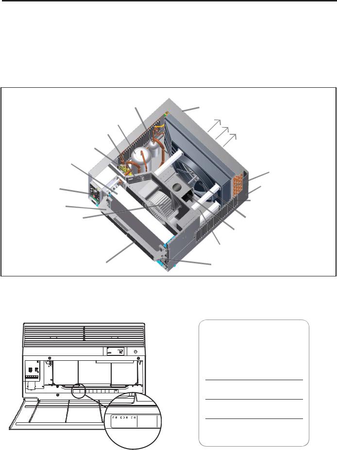
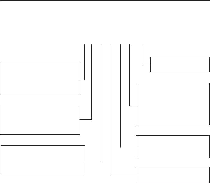
Accumulator |
Outdoor Grille |
|||
Compressor |
Discharge Air |
|||
Fresh Air Vent |
|
|
|
|
Reversing Valve |
|
|
|
|
Evaporator Coil |
|
|
|
|
Electronic Control |
|
|
Condenser Coil |
|
|
Sleeve |
|||
Board |
|
|||
Control Key Pad |
|
|
Air Intake Vents |
|
|
|
|||
Support Bar |
|
|
|
|
Blower Wheel |
Fan Blade |
|||
Air Intake From |
Fan/Blower Motor |
|||
Sides and Bottom |
Base Pan |
|||
|
||||
Control Key Pad |
Chassis Pull |
|||
(User Interface) |
||||
Out Handle |
||||
|
||||
IMPORTANT: It will be necessary for you to accurately identify the unit you are servicing, so you can be certain of a proper diagnosis and repair (See Unit Identification code on page 6).
MODEL AND SERIAL NUMBER LOCATION
UL |
Register the air conditioner
Model information can be found on the name plate behind the front cover.
For your future convenience, record the model information here.
MODEL NUMBER


 MODEL NUMBER AIR CONDITIONING CO.
  YS10M10A
  SAN ANTONIO, TEXAS SERIAL NUMBER ASSEMBLED IN MEXICO LICY00008
SERIAL NUMBER
PURCHASE DATE
5
UNIT IDENTIFICATION
Model Number Code
S S 08 M 1 0 A
1st Digit – Function
S = Straight Cool, Value Series Y = Heat Pump
E = Electric Heat
2nd Digit
S = Small Chassis M = Medium Chassis L = Large Chassis
3rd and 4th Digit - Approximate BTU/HR in 1000s (Cooling)
Heating BTU/Hr capacity listed in the Specification/Performance Data Section
8th Digit – Engineering
Major change
7th Digit – Options
0 = Straight Cool &
Heat Pump Models
3 = 3 KW Heat Strip, Nominal
4 = 4 KW Heat Strip, Nominal
5 = 5 KW Heat Strip, Nominal
6th Digit – Voltage
1 = 115 Volts
3 = 230-208 Volts
5th Digit
Alphabetical Modifier
RAC Serial Number Identification Guide
Serial Number |
|
A |
K |
A |
R |
00001 |
|
Decade Manufactured |
|
|
|
|
|
||
L=0 |
C=3 |
F=6 |
J=9 |
|
|
|
Production Run Number |
A=1 |
D=4 |
G=7 |
|
|
|
|
|
B=2 |
E=5 |
H=8 |
|
|
|
|
Product Line |
|
|
|
|
|
|||
Year Manufactured |
|
|
|
|
|||
A=1 |
D=4 |
G=7 |
K=0 |
|
|
|
R = RAC |
B=2 |
E=5 |
H=8 |
|
|
|
|
|
C=3 |
F=6 |
J=9 |
|
|
|
|
|
|
|
|
|
|
|
||
Month Manufactured |
|
|
|
|
|
||
A=Jan D=Apr G=Jul K=Oct |
|
|
|
|
|||
B=Feb E=May H=Aug L=Nov |
|
|
|
|
|||
C=Mar F=Jun J=Sept M=Dec |
|
|
|
|
|||
|
|
|
|
|
|
|
|
6

PERFORMANCE DATA
COOLING |
EVAP. AIR TEMP. DEG. |
CONDENSER |
Discharge |
Suction |
|
Sub- |
OPERATING |
ELECTRICAL RATINGS |
R-410A |
|
BREAKER |
||||
F |
|
|
PRESSURES |
REF. |
|
FUSE |
|||||||||
PERFORMANCE |
|
Super Heat |
|
|
|
Voltage |
|||||||||
DATA* |
Discharge Air |
Temp. |
TEMP DEG. F |
Temp |
Temp |
|
Cooling |
Suction |
Discharge |
Amps |
Amps |
Locked Rotor |
Charge in |
|
60 Hertz |
Drop F. |
|
|
|
|
|
Cool |
Heat |
Amps |
OZ. |
|
Amps |
||||
SS08M10-A |
53 |
27 |
115 |
157 |
62 |
12 |
31 |
151 |
400 |
6.1 |
|
32.0 |
24.0 |
115 |
15 |
SS10M10-A |
52 |
28 |
119 |
150 |
65 |
15 |
28 |
145 |
455 |
8.0 |
|
50.0 |
51.0 |
115 |
15 |
SS12M10-A |
50 |
30 |
118 |
163 |
60 |
12 |
23 |
137 |
435 |
10.0 |
|
57.0 |
35.0 |
115 |
15 |
SS14M10-A |
49 |
31 |
121 |
170 |
56 |
10 |
22 |
132 |
425 |
12.0 |
|
63.0 |
29.0 |
115 |
15 |
YS10M10-A |
56 |
24 |
114 |
150 |
64 |
12 |
14 |
152 |
395 |
7.8 |
7.6 |
34.5 |
33.0 |
115 |
15 |
SS12M30-A |
49 |
31 |
116 |
158 |
62 |
13 |
21 |
142 |
405 |
4.8 |
|
30.0 |
33.0 |
230/208v |
15 |
ES12M33-A |
51 |
29 |
115 |
158 |
62 |
13 |
18 |
140 |
400 |
4.8 |
16.0 |
30.0 |
33.0 |
230/208v |
15 |
YS12M33-A |
49 |
31 |
116 |
167 |
65 |
16 |
21 |
140 |
455 |
5.2 |
5.1 |
26.0 |
34.5 |
230/208v |
15 |
SS15M30-A |
53 |
27 |
121 |
171 |
62 |
14 |
28 |
138 |
430 |
6.4 |
|
32.0 |
32.5 |
230/208v |
15 |
ES15M33-A |
53 |
27 |
121 |
171 |
62 |
14 |
28 |
138 |
430 |
6.4 |
16.0 |
32.0 |
32.5 |
230/208v |
15 |
SM18M30-A |
54 |
26 |
122 |
160 |
62 |
9 |
31 |
145 |
450 |
7.4 |
|
42.0 |
55.0 |
230/208v |
15 |
EM18M34-A |
54 |
26 |
122 |
160 |
62 |
9 |
31 |
145 |
450 |
7.4 |
19.5 |
42.0 |
55.0 |
230/208v |
30 |
YM18M34-A |
50 |
30 |
118 |
168 |
60 |
15 |
24 |
130 |
410 |
8.5 |
8.5 |
44.0 |
49.5 |
230/208v |
15 |
SM21M30-A |
48 |
32 |
124 |
170 |
55 |
10 |
28 |
137 |
455 |
9.4 |
|
46.0 |
55.0 |
230/208v |
15 |
SM24M30-A |
46 |
34 |
129 |
179 |
55 |
12 |
34 |
123 |
495 |
11.0 |
|
47.0 |
40.0 |
230/208v |
20 |
EM24M34-A |
46 |
34 |
129 |
179 |
55 |
12 |
34 |
123 |
495 |
11.0 |
|
47.0 |
40.0 |
230/208v |
30 |
YL24M34-A |
56 |
24 |
121 |
176 |
62 |
18 |
25 |
135 |
480 |
11.1 |
12.2 |
47.0 |
74.0 |
230/208V |
30 |
SL28M30-A |
47 |
33 |
126 |
181 |
58 |
12 |
26 |
133 |
430 |
13.5 |
|
60.0 |
78.5 |
230/208v |
20 |
SL36M30-A |
51 |
29 |
129 |
188 |
56 |
12 |
31 |
122 |
470 |
19.0 |
|
96.0 |
77.0 |
230/208v |
30 |
*Rating Conditions: 80 degrees F, room air temp. & 50% relative humidity, with 95 degree F, outside air temp & 40% relative humidity, all systems use R-410A.
SPECIFICATIONS |
|
|
|
|
|
ENERGY STAR® qualified |
|
|
|||||||
|
|
|
|
|
|
|
|
|
|
Energy |
Estimated |
|
Room Side |
|
|
|
|
|
|
|
|
|
|
|
|
Efficiency Yearly Moisture |
Air |
|
Net |
||
|
|
Cooling |
Heating |
Volts |
Cooling |
Cooling |
Heating |
Heating |
|
Ratio |
Operating |
Removal |
Circulation |
|
Weight |
|
Model |
Capacity Btu |
Capacity Btu |
Rated |
Amps |
Watts |
Amps |
Watts |
COP |
EER |
Cost |
Pints/HR |
CFM |
Sleeve |
Lbs |
|
Kühl |
|
|
|
|
|
|
|
|
|
|
|
|
|
|
|
|
|
|
|
|
|
|
|
|
|
|
|
|
|
|
|
SS08M10 |
7900 |
— |
115 |
6.1 |
677 |
— |
— |
— |
11.7 |
$54 |
1.0 |
265 |
S |
99 |
|
|
|
|
|
|
|
|
|
|
|
|
|
|
|
|
|
SS10M10 |
9500 |
— |
115 |
7.7 |
848 |
— |
— |
— |
11.2 |
$68 |
2.0 |
260 |
S |
106 |
|
SS12M10 |
12000 |
— |
115 |
10.0 |
1071 |
— |
— |
— |
11.2 |
$86 |
3.0 |
300 |
S |
112 |
|
SS14M10 |
14000 |
— |
115 |
12.0 |
1444 |
— |
— |
— |
9.7 |
$115 |
3.5 |
325 |
S |
116 |
|
|
|
|
|
|
|
|
|
|
|
|
|
|
|
|
|
SS12M30 |
11700/11200 |
— |
230/208 |
4.8/4.9 |
1026/982 |
— |
— |
— |
11.4/11.4 |
$82 |
2.8 |
275 |
S |
112 |
|
SS15M30 |
14500/14300 |
— |
230/208 |
6.4/6.8 |
1405/1385 |
— |
— |
— |
10.3/10.3 |
$112 |
3.5 |
360 |
S |
116 |
|
|
|
|
|
|
|
|
|
|
|
|
|
|
|
|
|
SM18M30 |
17500/17200 |
— |
230/208 |
7.4/8.0 |
1635/1617 |
— |
— |
— |
10.7/10.7 |
$131 |
4.6 |
350 |
M |
140 |
|
|
|
|
|
|
|
|
|
|
|
|
|
|
|
|
|
SM21M30 |
20800/20700 |
— |
230/208 |
9.4/10.3 |
2080/2070 |
— |
— |
— |
10.0/10.0 |
$166 |
6.0 |
425 |
M |
132 |
|
SM24M30 |
23500/23300 |
— |
230/208 |
11.2/11.9 |
2500/2479 |
— |
— |
— |
9.4/9.4 |
$200 |
10.0 |
390 |
M |
152 |
|
|
|
|
|
|
|
|
|
|
|
|
|
|
|
|
|
SL28M30 |
27800/27000 |
— |
230/208 |
13.5/14.4 |
2865/2812 |
— |
— |
— |
9.7/9.6 |
$229 |
8.5 |
600 |
L |
193 |
|
SL36M30 |
36000/35700 |
— |
230/208 |
19.0/20.5 |
4235/4200 |
— |
— |
— |
8.5/8.5 |
$338 |
12.0 |
725 |
L |
212 |
|
Kühl + Heat Pump |
|
|
|
|
|
|
|
|
|
|
|
|
|
|
|
|
|
|
|
|
|
|
|
|
|
|
|
|
|
|
YS10M10* |
9500 |
7500 |
115 |
7.8 |
812 |
7.6 |
743 |
3.0 |
11.7 |
$65 |
1.9 |
285 |
S |
109 |
|
|
YS12M33 |
12100/12100 |
9400/9000 |
230/208 |
5.2/5.4 |
1120/1120 |
5.6/5.8 |
1132/1139 |
2.4 |
10.8/10.8 |
$89 |
3.0 |
265 |
S |
115 |
|
YM18M34 |
18200/17800 |
15500/15400 |
230/208 |
8.5/8.9 |
1838/1798 |
8.5/8.7 |
1833/1761 |
2.6 |
9.9/9.9 |
$147 |
5.4 |
370 |
M |
141 |
|
YL24M35 |
24000/23600 |
23500/23200 |
230/208 |
11.1/12.0 |
2474/2433 |
12.2/14.3 |
2610/2575 |
2.6 |
9.7/9.7 |
† |
7.0 |
600 |
L |
197 |
|
Kühl + Electric Heat |
|
|
|
|
|
|
|
|
|
|
|
|
|
|
|
|
|
|
|
|
|
|
|
|
|
|
|
|
|
|
|
ES12M33 |
11700/11200 |
10700/8900 |
230/208 |
4.8/4.9 |
1026/982 |
16.0/14.7 |
3500/2900 |
3.3 |
11.4/11.4 |
$82 |
2.8 |
275 |
S |
113 |
|
ES15M33 |
14500/14300 |
10700/8900 |
230/208 |
6.4/6.8 |
1405/1385 |
16.0/14.7 |
3500/2900 |
3.0 |
10.3/10.3 |
$112 |
3.5 |
360 |
S |
117 |
|
EM18M34 |
17500/17200 |
13000/10600 |
230/208 |
7.4/8.0 |
1635/1617 |
19.5/17.0 |
4200/3500 |
3.1 |
10.7/10.7 |
$131 |
4.6 |
350 |
M |
141 |
|
|
|
|
|
|
|
|
|
|
|
|
|
|
|
|
|
EM24M34 |
23500/23300 |
13000/10600 |
230/208 |
11.2/11.9 |
2500/2479 |
19.5/17.0 |
4200/3500 |
3.1 |
9.4/9.4 |
$200 |
10.0 |
390 |
M |
153 |
|
|
|
|
|
|
|
|
|
|
|
|
|
|
|
|
|
EL36M35 |
36000/35700 |
17300/14300 |
230/208 |
19.0/20.5 |
4235/4200 |
24.0/22.4 |
5500/4650 |
2.5 |
8.5/8.5 |
$338 |
12.0 |
725 |
L |
213 |
* Operates on 115 volt and is not equipped with supplemental heat. Will not provide heat at temperatures below 40°F. Friedrich room air conditioners are designed to operate in outdoor temperatures from 60° F to 115° F.
Due to continuing research in new energy-saving technology, specifications are subject to change without notice.
As an ENERGY STAR® partner, Friedrich Air Conditioning Co. has determined that the selected ENERGY STAR® ( ) models meet the ENERGY STAR® guidelines for energy efficiency.
The consumerthrough the AHAM Room Air Conditioner Certification Programcan be certain that the AHAM Certification Seal accurately states the unit’s cooling and heating capacity rating, the amperes and the energy efficiency ratio.
Estimated yearly operating cost based on a 2007 national average electricity cost of 10.65 cents per kWh.
† The estimated yearly operating cost of this model was not available at the time the range was published.
R-410A
All models use environmentally friendly R-410A refrigerant.
7
Installation Information / Sleeve Dimensions
|
|
|
Depth |
Shell Depth to |
|
|
|
|
Thru-the-wall Installation |
||
|
|
|
Minimum |
Minimum |
Window Width |
|
Finished Hole |
||||
|
|
|
with Front |
Louvers |
Extension |
Extension |
|
|
|
|
|
Sleeve |
|
|
|
|
|
|
|
|
|
||
Height |
Width |
|
|
Into Room* |
Outside* |
Minimum** |
Maximum |
Height |
Width |
Max. Depth |
|
S |
15 15/16" |
25 15/16" |
29" |
8 ¾" |
5 ¾” |
16 15/16” |
27 3/8" |
42" |
16 3/16” |
26 3/16” |
7 3/8" |
M |
17 15/16" |
25 15/16" |
29" |
8 ¾" |
5 ¾” |
16 15/16” |
27 3/8" |
42" |
18 3/16” |
26 3/16” |
7 3/8” |
L |
20 3/16" |
28" |
35 ½” |
16 ½" |
5 3/8” |
18 15/16” |
29 7/8” |
42" |
20 3/8" |
28 ¼" |
15 1/8” |
*Minimum extensions when mounted in a window.
**Minimum widths achieved using one side curtain assembly as opposed to both in a standard installation. NOTE: S,M and L sleeves may be installed in window with no side kits if properly installed.
Circuit Rating/ Breaker
|
Circuit Rating |
|
|
Wall Outlet |
|||||||
Model |
Breaker or |
Plug Face |
Power Cord |
||||||||
T-D Fuse |
(NEMA#) |
Length (ft.) |
Appearance |
||||||||
SS08M10, SS10M10, SS12M10 and |
125V - 15A |
5 - 15P |
6 |
|
|
|
|
|
|
|
|
SS14M10. YS10M10. |
|
|
|
|
|
|
|
|
|||
|
|
|
|
|
|
|
|
|
|
Front |
|
|
|
|
|
|
|
|
|
|
|
|
|
SS12M30, SS15M30, SM18M30 and |
250V - 15A |
6 - 15P |
4 |
|
|
|
|
|
|
|
|
|
|
|
|
|
|
|
|
||||
SM21M30. |
|
|
|
|
|
|
|
|
|||
|
|
|
|
|
|
|
|
|
|
|
|
|
|
|
|
|
|
|
|
|
|
|
|
SM24M30, SL28M30. ES12M33, |
250V - 20A |
6 - 20P |
4 |
|
|
|
|
|
|
|
|
ES15M33. YS12M33 |
|
|
|
|
|
|
|
|
|||
|
|
|
|
|
|
|
|
|
|
|
|
|
|
|
|
|
|
|
|
|
|
|
|
SL36M30. EM18M34, EM24M34, |
250V - 30A |
6 - 30P |
4 |
|
|
|
|
|
|
|
|
|
|
|
|
|
|
|
|
||||
EL36M35. YM18M34 and YL24M35 |
|
|
|
|
|
|
|
|
|
|
|
 (C)
(C) 
(B) |
|
SIDE VIEW |
|
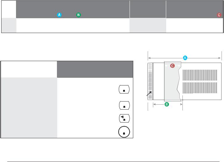
For the best cooling performance and highest energy efficiency
Keep the filter clean
Make sure that your air conditioner is always in top performing condition by cleaning the filter regularly.
Provide good air flow
Make sure the airflow to and from the unit is clear. Your air conditioner puts the conditioned air out at the top of the unit, and takes in unconditioned air at the bottom. Airflow is critical to good operation. It is just as important on the outside of the building that the airflow around the unit exterior is not blocked.
Insulation
Good insulation will be a big help in maintaining desirable comfort levels. Doors should have weather stripping. Be sure to caulk around doors and windows.
Proper installation of seal gasket
Make sure the seal gasket has been installed properly to minimize noise and improve efficiency. If the seal gasket has not been installed, please refer to the installation instructions.
Unit placement
If your air conditioner can be placed in a window or wall that is shaded by a tree or another building, the unit will operate even more efficiently. Using drapes or blinds on the sunny side of the dwelling will also add to your unit’s efficiency.
8
ELECTRICAL DATA
 WARNING
ELECTRIC SHOCK HAZARD
Turn off electric power before service or installation.
All electrical connections and wiring MUST be installed by a qualified electrician and conform to the National Electrical Code and all local codes
which have jurisdiction.
Failure to do so can result in personal injury or death.
|
NOTICE |
|
|
FIRE HAZARD |
|
|
Not following the above WARNING could result in fire or |
|
|
electically unsafe conditions which could cause moderate |
|
|
or serious property damage. |
|
|
Read, understand and follow the above warning. |
|
Wire Size |
Use ONLY wiring size recommended for single outlet branch circuit. |
|
Fuse/Circuit Breaker |
Use ONLY the correct HACR type and size fuse/circuit breaker. Read electrical ratings on unit’s |
|
|
rating plate. Proper circuit protection is the responsibiity of the homeowner. |
|
Grounding |
Unit MUST be grounded from branch circuit through service cord to unit, or through separate |
|
|
ground wire provided on permanently connected units. Be sure that branch circuit or general |
|
|
purpose outlet is grounded. |
|
Receptacle |
The field supplied outlet must match plug on service cord and be within reach of service cord. |
|
|
Do NOT alter the service cord or plug. Do NOT use an extension cord. Refer to the table above |
|
|
for proper receptacle and fuse type. |
|
The consumer - through the AHAM Room Air Conditioner Certification Program - can be certain that the AHAM Certification Seal accurately states the unit’s cooling and heating capacity rating, the amperes and the energy efficiency ratio.
*HACR: Heating Air Conditioning and Refrigeration
9
WARNING: Before Operating Your Unit
 WARNING
Electrical Shock Hazard
Make sure your electrical receptacle has the same configuration as your air conditioner’s plug. If different, consult a Licensed Electrician.
Do not use plug adapters.
Do not use an extension cord.
Do not remove ground prong.
Always plug into a grounded 3 prong oulet. Failure to follow these instructions can result in death, fire, or electrical shock.
NOTICE
Do not use the LCDI device as an ON/OFF switch.
Failure to adhere to this precaution may cause premature equipment malfunction.
Once plugged in, the unit will operate normally without the need to reset the LCDI device. If the LCDI device fails to trip when tested or if the power supply cord is damaged, it must be replaced with a new power supply cord from the manufacturer. Contact our Technical Assistance Line at (800) 541-6645. To expedite service, please have your model number available.
Make sure the wiring is adequate for your unit.
If you have fuses, they should be of the time delay type. Before you install or relocate this unit, be sure that the amperage rating of the circuit breaker or time delay fuse does not exceed the amp rating listed in Table 1.
DO NOT use an extension cord.
The cord provided will carry the proper amount of electrical power to the unit; an extension cord may not.
Make sure that the receptacle is compatible with the air conditioner cord plug provided.
Proper grounding must be maintained at all times. Two prong receptacles
The grounded receptacle should meet all national and local codes and ordinances. You must use the three prong plug furnished with the air conditioner. Under no circumstances should you remove the ground prong from the plug.
Test the power cord
All Friedrich room air conditioners are shipped from the factory with a Leakage Current Detection Interrupter (LCDI) equipped power cord. The LCDI device on the end of the cord meets the UL and NEC requirements for cord connected air conditioners.
To test your power supply cord:
1.Plug power supply cord into a grounded 3 prong outlet.
2.Press RESET (See Figure 1).
3.Press TEST, listen for click; the RESET button trips and pops out.
4.Press and release RESET (Listen for click; RESET button latches and remains in). The power cord is ready for use.
Table 1.
|
CIRCUIT RATING |
REQUIRED |
||||||||||
|
OR TIME DELAY |
WALL |
||||||||||
MODEL |
FUSE |
RECEPTACLE |
||||||||||
|
AMP |
VOLT |
NEMA |
|
|
|
|
|
|
|
|
|
|
NO. |
|
|
|
|
|
|
|
|
|
||
|
|
|
|
|
|
|
|
|
|
|
|
|
SS08M10, SS10M10, |
|
|
|
|
|
|
|
|
|
|
|
|
SS12M10, SS14M10, |
15 |
125 |
5-15R |
|
|
|
|
|
|
|
|
|
|
|
|
|
|
|
|
|
|
||||
YS10M10 |
|
|
|
|
|
|
|
|
|
|
|
|
|
|
|
|
|
|
|
|
|
|
|
|
|
SS12M30, SS15M30, |
15 |
250 |
6-15R |
|
|
|
|
|
|
|
|
|
SM18M30, SM21M30 |
|
|
|
|
|
|
|
|
|
|||
|
|
|
|
|
|
|
|
|
|
|
|
|
|
|
|
|
|
|
|
|
|
|
|
|
|
SL25M30, SL28M30, |
|
|
|
|
|
|
|
|
|
|
|
|
ES12M33, ES15M33, |
20 |
250 |
6-20R |
|
|
|
|
|
|
|
|
|
|
|
|
|
|
|
|
|
|
||||
YS12M33 |
|
|
|
|
|
|
|
|
|
|
|
|
SL36M30, EM18M34, |
|
|
|
|
|
|
|
|
|
|
|
|
EL25M35, EL36M35, |
30 |
250 |
6-30R |
|
|
|
|
|
|
|
|
|
|
|
|
|
|
|
|
|
|
||||
YM18M34, YL24M35 |
|
|
|
|
|
|
|
|
|
|
|
|
|
|
|
|
|
|
|
|
|
|
|
|
|
Figure 1
RESET TEST
WARNING
TEST BEFORE EACH USE
1.PRESS RESET BUTTON
2.PLUG LCDI INTO POWER RECEPTACLE
3.PRESS TEST BUTTON, RESET BUTTON SHOULD
 POP UP
4.PRESS TEST BUTTON, FOR USE
DO NOT USE IF ABOVE TEST
FAILS
WHEN GREEN LIGHT IS ON
IT IS WORKING PROPERLY
TEST
RESET
WARNING
TEST BEFORE EACH USE
1.PRESS RESET BUTTON
2.PLUG LCDI INTO POWER RECEPTACLE
3.PRESS TEST BUTTON, RESET BUTTON SHOULD POP UP
4.PRESS TEST BUTTON, FOR USE
DO NOT USE IF ABOVE TEST FAILS
WHEN GREEN LIGHT IS ON IT IS WORKING PROPERLY
15/20A LCDI Device |
30A LCDI Device |
FRR001
10
Control Panel Operation
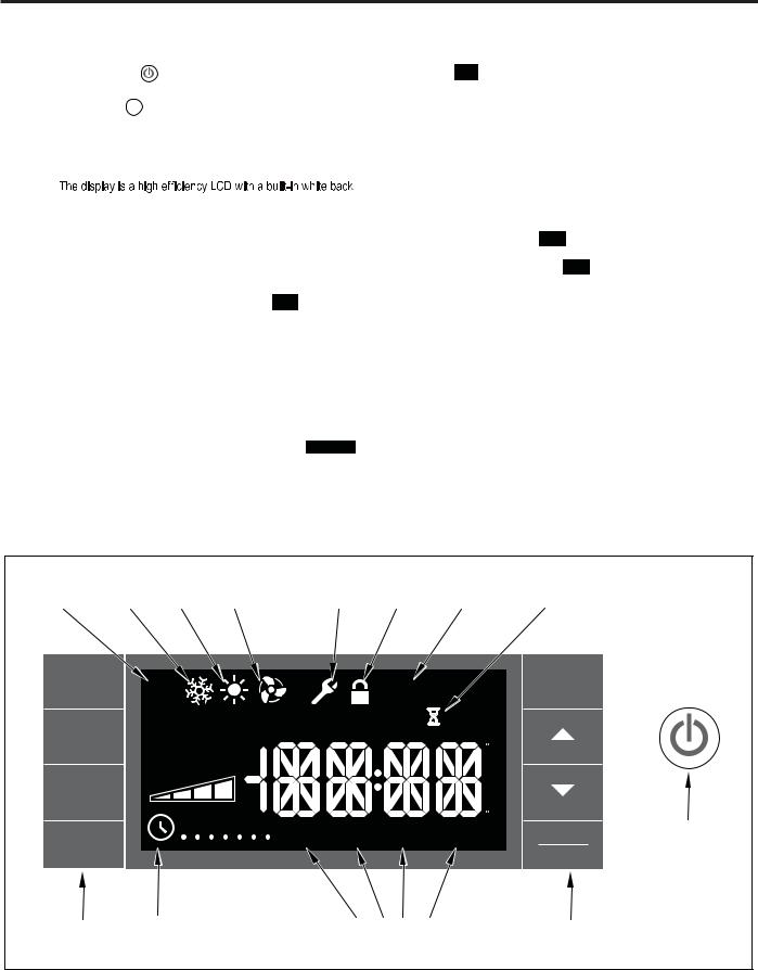
Let’s check out how to control your air conditioner. On the control panel, just to the left of the POWER , is a liquid crystal display (LCD). All of the control panel function buttons and mode icons can be viewed in Figure 1.
Power On – Press the  button to turn on the air conditioner. The power button will illuminate to indicate the power is on. The backlight on the power switch will automatically dim to 20% intensity after 120 seconds of inactivity. The remote control can also be used to turn power ON / OFF (See Remote Control).
Display –
light. The back light has an automatic two (2) step dim function. After 120 seconds of inactivity, the display dims to 20% intensity. After an additional 120 seconds, the display switches off. Touching buttons will automatically bring the display to full brightness.
There are four control push buttons on each side of the display. SYSTEM Button – Allows the user to sequentially select,  Cool
Cool
 , HEAT
  , and FAN ONLY
  operation. Press the

 button and the display advances to the next mode. A new icon appears. At the same time, the mode displays for two (2) seconds, then returns the display to the temperature set point for modes other than FAN. Note that on cool only units, there are no HEAT
  and
and  modes.
FAN MODE Button – Selects between automatic  or
or  operation. In the
  mode, the fan only turns on and off when the compressor operates or the heat function is enabled.
In the SYSTEM FAN ONLY Mode,  is not available. In the


mode, fans speed is determined by your selection on the  button.
Figure 1
FAN SPEED Button – Used to sequentially select between fan speeds. Depending on your model, you can select between LOW, MED, HIGH, and MAX and AUTO. Max setting not available on SL and Kuhl+ models. When the 

 button is pressed, the fan speed is temporarily displayed in the display window, plus a fan speed icon (triangle) changes to indicate the new speed level. When auto is selected, fan speed automatically varies depending on the set temperature on the control panel and the actual room temperature. Let me explain. Say for example you’re working in your garage and you need to open the big door for several minutes. The air conditioner will sense a wide difference between the set temperature and the actual room temperature when this occurs the system fan speed increases to MAX. The fan speed decreases (in step) as the temperature difference decreases. When the set point temperature is reached the FAN speed returns to the original setting.
SCHEDULE Button – The 


 button turns the schedule function on and off. The current day of the week is indicated as a dot underneath the day symbol. Pressing the


 button a second time turns the schedule function off. The schedule function comes preprogrammed with recommended energy savings values (Addendum 1). The values may be changed through the schedule program function (See Programmable Thermostat).
UP and DOWN arrows – Pressing either  (UP) or
  (DOWN) button changes the desired room temperature. The factory preset lower and upper limits are 63° F (16° C) and 99° F (37° C). These buttons are also used to navigate between function options when using the User Menu or Maintenance Mode.
BACK Button – This button is used after a menu item has been selected. It takes the user back to the previous menu level and to save and exit.
DISPLAY/ENTER Button – This button is used in conjunction with User Menu and Maintenance Mode operation to select items. This button may also be used to alternatively display the ROOM TEMPERATURE, OUTDOOR TEMPERATURE, and TIME. If the display is left inactive for 10 seconds it will reset to the TEMPERATURE SET POINT.
AUTO |
COOL |
HEAT |
|
FAN |
|
|
MAINTENANCE |
FRONT |
FILTER |
|
|
|||
|
ONLY |
|
|
PANE L |
|
|
||||||||
MODE |
MODE |
MODE |
|
MODE |
|
REQUIRED |
LOCK |
MAINTENANCE |
WAIT |
|
||||
SYSTEM |
|
|
AU TO |
|
|
|
|
|
|
CHECK |
ON |
EXIT |
BACK |
|
|
|
|
|
|
|
|
|
|
|
|||||
|
|
|
|
|
|
|
|
|
FI LTER |
OFF |
RESET |
|
|
|
|
|
|
|
|
|
|
|
|
|
|
|
|||
FAN |
|
|
AU TO |
|
|
|
|
OUTDOOR |
TEMP |
|
|
|
|
|
|
|
|
|
|
|
ROOM TEMP |
HE AT -> SET POINT |
<- COOL |
|
|
||||
MODE |
|
|
|
|
|
|
|
|
|
|||||
|
|
CONTINUOUS |
|
|
|
|
|
|
|
F |
|
|
||
|
|
|
|
|
|
|
|
|
|
|
|
|||
|
|
|
|
|
|
|
|
|
|
|
|
A |
|
|
FAN |
|
|
AU TO |
|
|
|
|
|
|
|
|
M |
|
|
|
|
|
|
|
|
|
|
|
|
P |
|
|
||
SPEED |
|
|
|
|
|
|
|
|
|
|
|
M |
|
|
|
|
|
|
|
|
|
|
|
|
|
|
|
|
|
|
|
|
M T |
W |
T F |
S |
S |
|
|
|
|
C |
|
|
SCHEDULE |
|
WAKE |
AWAY |
R E TURN |
NIGHT |
DISPLAY |
POWER |
|||||||
|
|
|
|
|
|
|
||||||||
|
|
|
|
|
|
|
|
|
|
|
ENTER |
|
||
|
|
|
|
|
|
|
|
|
|
|
|
|
|
|
BUTTONS |
SCHEDULE |
|
|
|
|
|
SCHEDULE |
|
|
BUTTONS |
|
|||
|
|
ON/OFF |
|
|
|
|
|
|
PERIODS |
|
|
|
|
|
11
ALERTS (The control system has five (5) customer alerts)
CHECK FILTER |
|
|
|
|
|
|
appears on screen. The word “ |
|
” appears next to the |
|
button. |
||
The |
alert is issued when the fan |
run time is greater than 500 hours. |
||||
This alert may be reset by the user (Refer to Special Functions, Filter Reset).
Maintenance Required – When maintenance is required, a service icon
 appears on screen. This icon will not be dismissed until maintenance has been performed. If the service icon
the icon  is on standby the system has sensed an abnormal condition. is established the service icon
  goes away.
Wait – The WAIT icon  illuminates when the compressor lockout is active. Whenever the compressor shuts off, system pressures must be allowed to equalize. At this time, an internal timer begins a count-down from up to 240 seconds. If a demand for heat or cool occurs during this count-down
the WAIT icon  displays letting you know that the compressor will not operate until the count-down has completed. This timer prevents damage to the unit if it tries to start too quickly after it stops running. Normally the WAIT icon
  is off. Once the timer has cleared, the air conditioner will heat or cool based on the temperature setting. Electric heat is not affected by this timer.
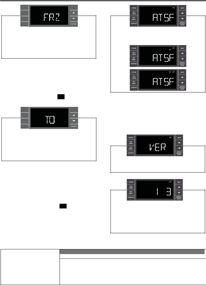
Protection Alert (Freeze) – If the room freeze protection is active, the display indicates this by showing Room Freeze Protection "FRZ". Once
temperature is less than 40° F (4° C), and the air conditioner is equipped with electric heat, the room freeze protection will activate. The air conditioner will run high fan and electric heat until the room temperature reaches 46° F (8° C). Pressing the button delays the freeze protection function
Low Battery – When the battery is low a warning display
 will be inserted before other messages such as “COOL”. If the Low Battery
 alert is on, the battery in the control unit must be changed. Refer to the changing the battery procedure. Once the battery is changed, the alert message will go off. Refer to Troubleshooting Tips. Under normal conditions the battery life should be greater than 7 years.
Special Functions
Panel Lock  – The front panel push buttons can be locked to prevent inadvertent operation. To lock the front panel, press and hold the SCHEDULE +
  buttons for three (3) seconds. A double beep indicates your mode change was successful and a
  icon appears on the display. To unlock the display, press and hold the SCHEDULE +

 buttons for three (3) seconds.
The  icon will no longer be visible.
Filter Reset – 


 icon displays, the timer may be reset by pressing and holding the
 button for three (3) seconds. A beep indicates the

 system timer was reset and the

 icon and the word " RESE T " will no longer be visible.
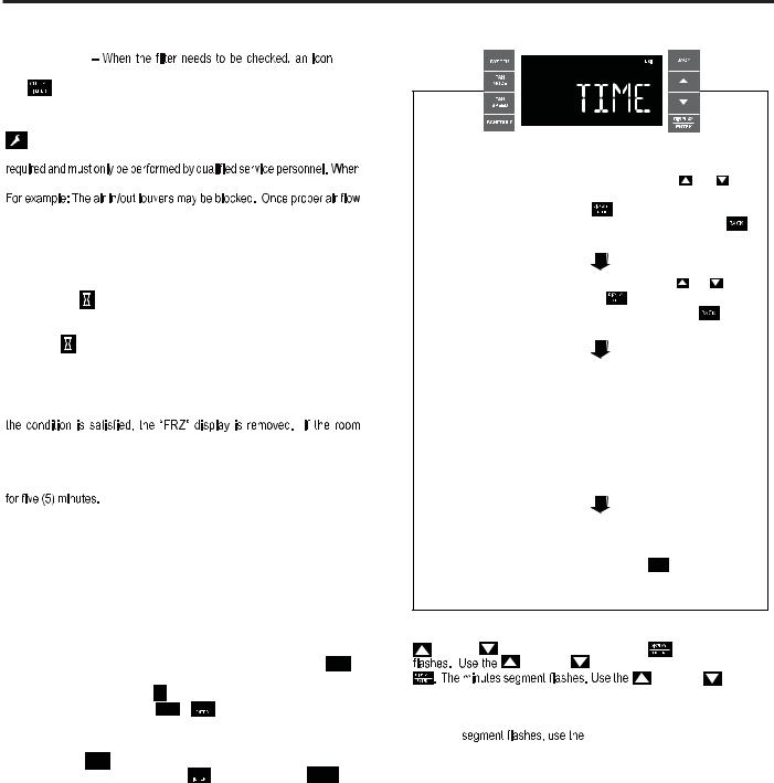
User Menu Functions – The User Menu Functions allows you to change the following selections: Set TIME, 12/24 Hour Clock Format, BEEP ON / OFF, DIM ON / OFF, Emergency Heat (EMHT) ON / OFF, Auto BAND Adjust, F/ C Select, FRZ ON / OFF, Temp Offset (TO) and the Automatic Temperature Sensing Feature (ATSF).
To enter the User Menu, press and hold  for 3 seconds, the TIME selection appears. Use the
  (UP) or
  (DOWN) buttons to scroll through the User Menu. Press the
  button to enter the displayed function. If left inactive for 15 minutes the User Menu display will no longer be visible and it returns to normal operation mode display. To manually exit the User Menu, press the
  button.
|
|
|
|
|
|
|
|
|
|
|
|
|
|
|
|
|
|
|
|
|
The hour digits flash first. The user presses the |
or |
|||||
to change the hours. To change AM-PM, the hours must be |
||||||
advanced 12 hours. Press the |
key to change to the |
|||||
minutes. To exit the selection process, user presses the |
||||||
key which will go to the time screen. |
|
|||||
The minutes digits flash. The user presses the |
or |
|||||
to change the minutes. Press the |
key to change the days. |
|||||
To exit the selection process, the user presses the |
key |
|||||
which will go to the time screen. |
|
|
|
|
||
The dot underneath the days of the week begins to blink to indicate which day it is. If the user has not set the date before, the dot starts on Monday. If the user is making a correction to previously set information the dot appears under whichever day the unit thinks it is. The user can press  or
or  to move the dot left or right (respectively) along the week. The user presses
  to loop back to the hours setting. To exit the selection process, the user presses the
  key which will go to the time screen.
Tuesday has been selected. The user presses  to loop back to the hours setting. To exit the selection process and accept the changes, the user presses the BACK key which will go to the time screen.
Time Setting – When in the User Menu, on the Control Panel, use the
(UP) and |
(DOWN) to select TIME. Push |
, the hours segment |
||
|
(UP) and |
(DOWN) to set the hour, then push |
||
|
|
|
(UP) and |
(DOWN) |
to set the minutes, then push  .
.
NOTE: If the AM or PM indicator is incorrect, push  until the hours
  (UP) or
  (DOWN) to advance the hour segment 12 hours, then push
  . The day of the week
displays. Use the  (UP) or
  (DOWN) to select the current day. Press the
  key to save and go back to the TIME screen.
Press  (UP) to go to the next menu 1224.
NOTE: Pressing the  button again will exit the user menu function mode. Or simply leave the control inactive for 15 minutes and the control will return back to normal operation.
12
SYSTEM |
EXIT |
BACK |
FAN
MODE
FAN
SPEED
SCHEDULE
DISPLAY
ENTER
User presses  or
or  to toggle the format between 12HR and 24HR display. To exit the selection process and accept the change, press the
  key.
key.
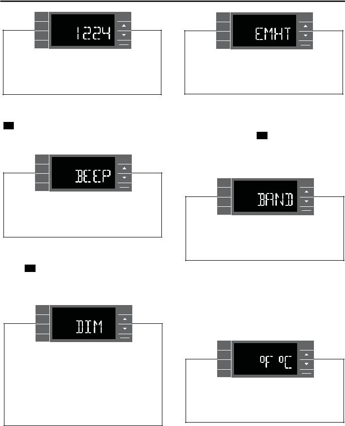
Clock Type – You may select between a 12 hr and 24 hr clock. When 1224 is displayed press the  key then press
  (UP) or
  (DOWN) to toggle between 12 hr and 24 hr clock. To accept the change, press the
 key to return to the 1224 screen. Press the
  (UP) to go to the next menu BEEP.
SYSTEM |
EXIT |
BACK |
FAN
MODE
FAN
SPEED
SCHEDULE
DISPLAY
ENTER
User presses  or
or  to toggle between Beep On and Beep Off. Press the
  key to accept the change and exit the selection process.
Audible Alerts – You can select to have the control beep when entering menus. When BEEP is displayed press the  key then press
  (UP) or
  (DOWN) to toggle between ON and OFF. To accept the change, press the
 key to return to the BEEP screen. Press the
  (UP) to go to the next menu EMHT on Kühl+ models or F C for Kühl models.
FAN
SPEED
SCHEDULE
DISPLAY
ENTER
User presses  or
or  to select between AUTO, DM 20, OFF. Press the
  key to accept the change and exit the selection process.
The Dim Auto automatically dims the display to 20% and then turns it off after a period of time. The Dim 20 setting behavior is similar to AUTO, but prevents the display from turning off. Minimum brightness is 20%. The Dim Off setting forces the display to run at full brightness.
SYSTEM |
EXIT |
BACK |
FAN
MODE
FAN
SPEED
SCHEDULE
DISPLAY
ENTER
User presses  or
or  to toggle between Emergency Heat On and Emergency Heat Off. Press the
  key to accept the change and exit the selection process.
Emergency Heat – The Kühl+ heat pump models (YS, YM, YL) have a special feature that is designed to keep the unit providing heat.
When EMHT is displayed press the  key then press
  (UP) or
  (DOWN) to toggle between ON and OFF.
To accept the change, press the 
 key to return to the EMHT screen. Press the
  (UP) to go to the next menu BAND.
In the unlikely event of a compressor failure, the heat pump unit may be switched to operate in the electric heat mode only until repairs can be made.
SYSTEM |
EXIT |
BACK |
FAN
MODE
FAN
SPEED
SCHEDULE
DISPLAY
ENTER
The menu allows the user to adjust the minimum spread between the Auto Cool set point and the Auto Heat set point. Press the  or
or  key to adjust. The adjust range is 3 to 10.
Auto Changeover ‘Dead Band’ – A buffer Zone between heating and cooling in which no conditioning occurs. For Kühl+ models with the auto changeover feature you can select the temperature band between heating and cooling. From the factory the band is set at 3° F (-16° C). The band is adjustable from 3° F (-16° C) to 10° F (-12° C). When BAND is displayed press the  key then press
  (UP) or
  (DOWN) to toggle between 3 and 10. To accept the change, press the
  key to return to the BAND screen. Press the
  (UP) to go to the next menu F C.
SYSTEM |
EXIT |
BACK |
FAN
MODE
FAN
SPEED
SCHEDULE
DISPLAY
ENTER
User presses  or
or  at the same time to toggle between Fahrenheit or Celsius as their temperature unit of choice. Press the
  key to accept the change and exit the selection process.
Fahrenheit / Celsius Selection – You may select between displaying temperature in F or C. When F C is displayed press the  key then press
  (UP) or
  (DOWN) to toggle between F and C. To accept the change, press the
  key to return to the F C screen. Press the
  (UP) to go to the next menu FRZ.
13
SYSTEM |
EXIT |
BACK |
FAN
MODE
FAN
SPEED
SCHEDULE
DISPLAY
ENTER
User presses  or
or  to select between Freeze Protection On & Freeze Protection Off. Press the
  key to accept the change and exit the selection process.
Freeze Protection – The Kühl+ models have a special feature that is designed to keep the interior space above freezing by energizing the electric heater anytime the indoor room temperature falls to 40° F (4° C). With the freeze protection feature turned on, when the unit senses the indoor temperature fall to 40° F (4° C) the unit will run the heater and high fan until the space reaches 46° F (8° C) When FRZ is displayed press the  key then press
  (UP) or
  (DOWN) to toggle between ON
and OFF. To accept the change, press the 
 key to return to the FRZ screen. Press the
  (UP) to go to the next menu TO.
SYSTEM |
EXIT |
BACK |
FAN
MODE
FAN
SPEED
SCHEDULE
DISPLAY
ENTER
User presses  or
or  to increment/decrement the temperature offset (TO) for the room temperature sensor. (Maximum offset = +/- 8 degrees F). Press the
  key to accept the change and exit the selection process
Temperature Offset – In some cases the built in thermostat on the unit may not display the temperature as it is felt in the room. This can be caused by many things including the size of the unit, the heat load on the room or other factors. Friedrich allows you to select the appropriate temperature offset to make the temperature readout as accurate as possible for your application. In many cases the factory 0° F (-18° C) offset will provide an accurate temperature readout. To change the offset follow these instructions. When TO is displayed press the 
 key then press
  (UP) or
  (DOWN) to toggle between 0° F (-18° C) and 8° F (-13° C). In most instances an offset from 0° F (-18° C) to 2° F (-17° C) is all that is necessary. To accept the change, press the
 key to return to the TO screen. Press the
  (UP) to go to the next menu ATSF.
You may cycle through the menus using the  (UP) or
  (DOWN) keys to access any of the menus.
User presses  or
or  to select between ATSF On or Off.
Press the  key to accept the change and exit the selection process.
Automatic Temperature Sampling Feature - The automatic temperature sampling feature maintains a balanced temperature throughout the room by circulating the air for 30 seconds once every 9 minutes that the unit is not running when it is set to cooling or heating mode. By circulating the air the unit can detect hot or cold areas in the room and operate the unit to cool or warm the room as necessary. This function is only available when the fan mode is set to ‘AUTO’ or in COOL or HEAT Mode. (Heating function only available on Kuhl+ units)
Y
For display only. No user selectable options.
Firmware Version - When VER is displayed press Display / Enter key. The firmware version is displayed as left digit (Major) and right digit (Minor). This version number should be used along with Model and Serial numbers for service.
DIGITAL CONTROL PANEL'S ACCESS CODES SUMMARY
Key Sequence |
|
Action |
Filter Reset |
Press BACK key for 3 sec + play double beep () |
|
Enter User Menu |
|
PressDISPLAY/ENTER key for 3 sec + play double beep () |
Enter Maintenance Menu |
|
Press SYSTEM + SCHEDULE + BACK + DISPLAY/ ENTER for 3 sec + play double beep () |
Schedule ON/OFF |
Press SCHEDULE once each time |
|
Enter & Exit Schedule Programming |
Press SCHEDULE for 3 sec + play double beep () |
|
Reset Error Codes & Error History |
Press + for 3 sec + play double beep () |
|
Lock Control Panel |
Press SCHEDULE + DISPLAY/ENTER for 3 sec + play double beep () |
|
14
Remote Control Operation
Remote Control – Refer to Figures 11 and 12 during operation description.
Getting Started – Install two (2) AAA batteries in the battery compartment located on the back of the unit.
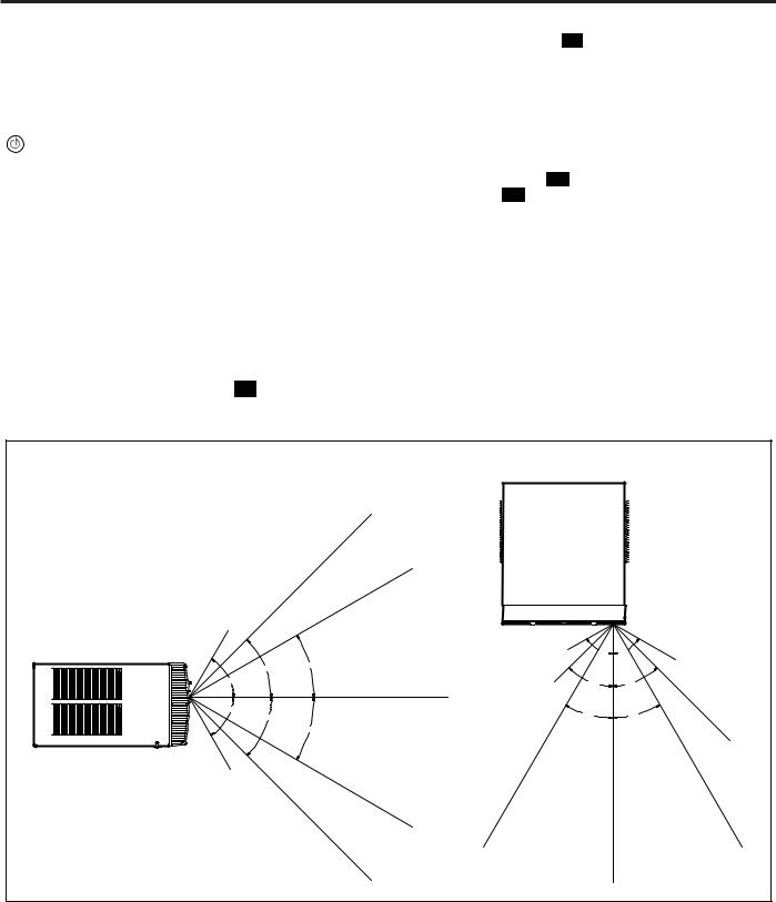
Operation – The remote control should be within 25 feet of the air conditioner for operation (Refer to Figure 10 for effectiveness). Press the button to turn the remote on. The remote will automatically power off after 15 seconds if the buttons are not being pressed. The remote must
be on to control the unit.
POWER Button – Turns remote and unit on and off.
SYSTEM Button – Allows the user to sequentially select,  Cool
Cool  , HEAT
 , and FAN ONLY
 operation. When the button is pressed, the display indicates which mode has been selected via a display message. Note that when the heating function is not available, the system will automatically skip the HEAT and AUTO modes.
FAN MODE Button – Selects between automatic ( ) or
) or 
operation. In the AUTO mode, the fan only turns on and off when the compressor operates or the heat function is enabled.
NOTE: AUTO is not available in the FAN ONLY Mode, the display indicates  . In the
  mode, fan speed is determined by your selection on the
  button.
FAN SPEED Button – Used to sequentially select new fan speed, plus AUTO operation. When the SPEEDFA N button is pressed, the fan speed is temporarily displayed in the display window, plus a fan speed icon (triangle) changes to indicate the new speed level. Fan speed automatically varies depending on the set temperature on the control panel and the actual room temperature. Let me explain. Say for example you’re working in your garage and you need to open the big door for several minutes. Since there is a big difference between your set temperature and the actual room temperature the system fan speed increases to MAX. It remains at this speed until the room temperature matches the set temperature.
SCHEDULE Button – The SCHEDULE button turns the schedule function on and off. Pressing the SCHEDULE button a second time turns the schedule function off. Only the schedule icon will be displayed.
UP and DOWN Arrows – Pressing either the  (UP) or
  (DOWN) button changes the desired room temperature. The factory preset lower and upper limits are 60° F (16° C) and 99° F (37° C). These buttons are also used to navigate between function options when using the User Menu or Maintenance Mode.
Remote Effectiveness
Hand Held Remote – Has an operating range of up to 25 ft. The infrared remote control signal must have a clear path to transmit the command to the air conditioning unit. The remote signal has some ability to "bounce" off of walls and furniture similar to a television remote control. The diagram below shows the typical operating range of the control in a standard room with 8 ft high ceilings.
|
|
TOP VIEW |
|
||
|
|
25ft |
|
|
|
|
|
25ft |
|
|
|
7.5ft |
|
|
|
|
|
SIDE VIEW |
|
|
4ft |
60° |
60° |
|
45° |
30° |
|
|
6ft |
|
|
|
|
||
|
|
|
|
|
|
60° |
|
8ft |
|
45° |
45° |
|
|
|
|||
|
|
25ft |
|
|
|
60° |
45° |
|
|
30° |
30° |
|
|
|
|||
|
|
30° |
|
|
|
|
|
|
|
|
16ft |
8ft |
|
|
|
|
|
|
|
25ft |
|
|
|
|
|
25ft |
|
|
25ft |
|
|
25ft |
|
|
25ft |
|
|
|
|
|
|
Changing Temperature from F˚ (Fahrenheit) To C˚ (Celsius) or Reverse
Be within 25' of unit with the remote control. Press the SYSTEM and FAN MODE buttons at the same time and hold for 3 seconds. The display will show the temperature in Celcius. Do the same to reverse temperature to F˚ (Fahrenheit).
15
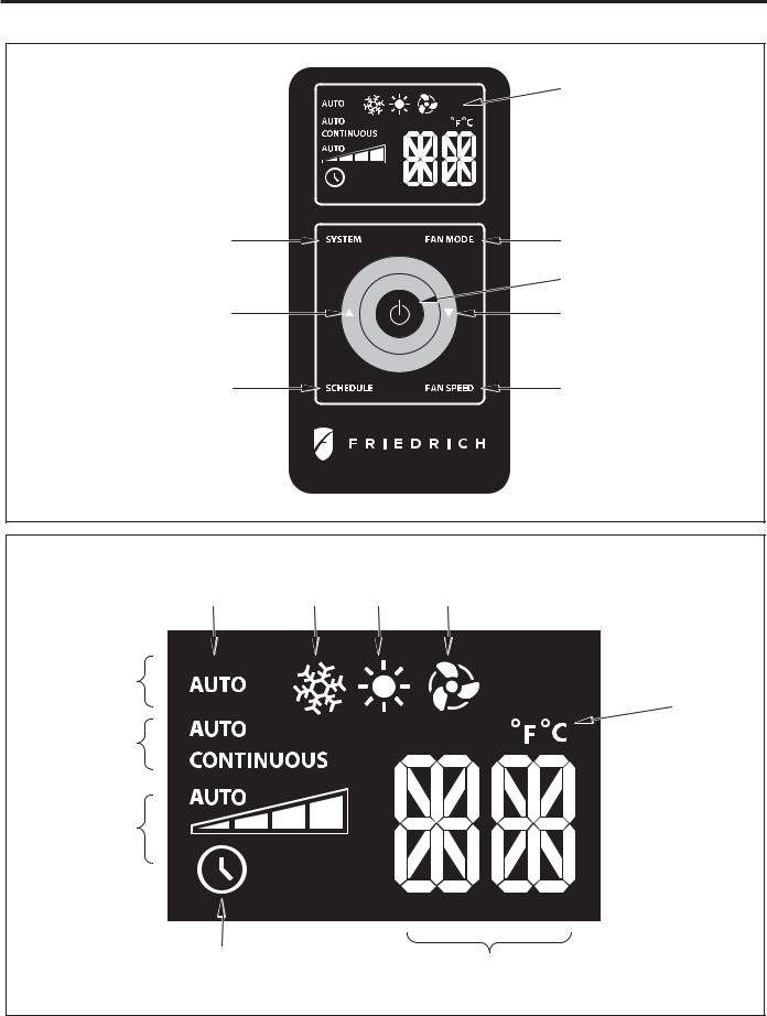
Remote Control Operation (Continued)
Figure 1
DISPLAY
SYSTEM |
FAN MODE |
|
POWER |
TEMPERATURE |
TEMPERATURE |
UP |
DOWN |
SCHEDULE |
FAN SPEED |
FRR005
Figure 2
AUTO |
COOL |
HEAT |
FAN ONLY |
ICON |
ICON |
ICON |
ICON |
SYSTEM
MODE
°F / °C
ICONs
FAN
MODE
FAN
SPEED
SCHEDULE |
2 X 16 SEGMENT |
|
ICON |
||
DISPLAY |
||
|
FRR006
16
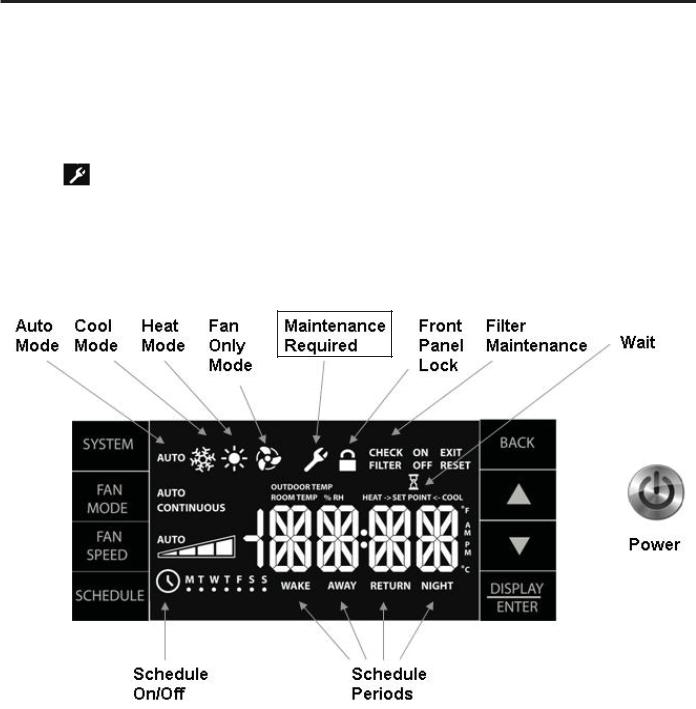
ELECTRONIC CONTROL SYSTEM MAINTENANCE
Introduction
This section contains information on the maintenance alerts, temperature limiting, diagnostic test and how to access. The electronic control system has a built in maintenance sub system which works constantly behind the scenes to help identify problems with the air conditioner or control system. When maintenance is required, a service icon appeasrs on the display screen.
This icon |
will not be dismissed until maintenance has been performed or the problem cleared. |
Note: The wrench icon may be on steady or flash, depending on severity. Maintenance should only be performed by qualified service personell.
Display
Testing the Display
Press the FAN MODE and FAN SPEED buttons at the same time for 3 seconds. All of the display's icons and functions should light up. If any of them do not light up, the display should be replaced. When the buttons are released, the display reverts to the original display.
17
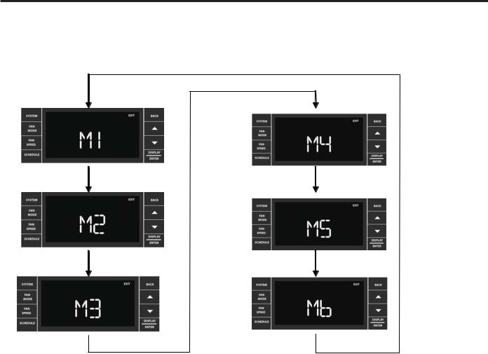
Electronic Control System Maintenance Operation
To Enter the Maintenance Section:
Press SYSTEM+SCHEDULE+BACK+DISPLAY/ENTER for 6 seconds.
There are 5 maintenance sub-menus M1 through M5.
|
Maintenance Sub-Menus |
|
Access |
|
|
M1 |
– Temperature High Limit |
Service Only |
|
M2 |
– Temperature Low Limit |
Service Only |
||
M3 |
– Test Mode Access |
Service Only |
||
M4 |
– Provision Switch Setting & State |
Factory Use Only |
||
M5 |
– Alarms & History |
Service Only |
||
M6 |
– Factory Use Only |
Factory Use Only |
||
Pressing the ▼or ▲key cycles through the sub-menus. Press DISPLAY/ENTER to enter a sub-menu. The BACK key is used to exit the menu. Extreme care must be taken when modifying parameters in the maintenance menus.
18
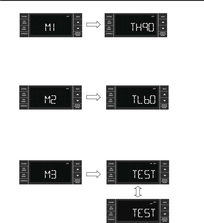
Temperature High Limit
Maintenance function 1 is ready to be selected. Press DISPLAY/ENTER to access the function.
User presses or to increment or decrement the upper temperature limit. 99°F is the maximum upper limit. The current stored high limit is displayed when the screen is selected. Press the BACK key to accept the value, and exit the sub-menu to the M1 screen.
Temperature Low Limit
Maintenance funtion 2 is ready to be selected. Press DISPLAY/ENTER to access the fuction
User presses or to increment or decrement the lower temperature limit. 60°F is the minimum lower limit. The current stored lower limit must be displayed when the screen
is selected. Press the BACK key to accept the value, and exit the sub-menu to the M2 screen.
M3 – Test Mode Access
Maintenance function 3 is ready to be selected. Press
DISPLAY/ENTER to access the function.
User presses the ▼or ▲key to toggle the Test Mode ON/OFF. Press the BACK key to accept the change and exit the sub-menu to the M3 screen.
This test selects the system mode of operation directly.
The Following functions Can be Tested
1. System Mode: Cool/Heat Pump Compressor, Electric Heat, Fan Only 2. Fan operation and speeds
Test mode Bypasses:
1. Compressor lock out (time delay)
2. All relay switch’s delays
3. All thermistors delay
4. Automatic heat/cool changeover delay
5. System settings
If M3 switch is left ON it will reset to OFF automatcally after 15 minutes of inactivity. |
19 |
|
M4 – Switch Access (Unit Configuration)
FACTORY USE ONLY
M5 – Error Codes & History
Number of Errors |
Error Code |
|
On/Off |
||
|
||
Error Code |
|
Maintenance funtion 5 is ready to be selected. Press DISPLAY/ENTER to access the function.
The error code display shows the error code number on the left, and the error code
history on the right. User presses the or keys to cycle through the error codes. The current state of the error code is shown with the On/Off icon. To exit the maintenance sub-menu, press the BACK key to return to the M5 screen.
Shown on this display is error code 1 with 4 occurances. The current state is on.The error code display shows the error code number on the left, and the error code history
on the right. User presses the or keys to cycle through the error codes. The current state of the error code is shown with the On/Off icon. To exit to the maintenance sub-menu, press the BACK key to return to the M5 screen. Shown on this display is error code 6 with 3 occurances. The current state is off.
To Clear Error Codes’ History:
Hold the or keys simultaneously for 3 seconds. See page 56 for alarm status and error codes.
M6 – Factory Use Only
20

UNIT OPERATION
There are two basic ways to operate the unit - Front Panel and Wallstat. The Front Panel and Wallstat are never active at the same time. Switching between these modes is controlled via the (FP) jumper on the Wallstat connector. When the jumper is ON, the mode = Front Panel.
Front Panel
System Mode Sequence (SCHEDULE = OFF)
There are two system modes of operation. One for a cool only unit (see figure 1) and one for a heat-cool unit (see figure 2). System parameters for each system mode are saved when exiting a system mode, and retrieved when entering a new system mode.
Figure 1
System Mode: Cool Only Units
Figure 2
System Mode: Heat - Cool Units
21
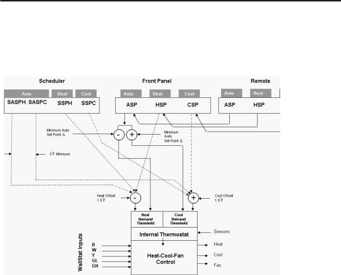
COOL-HEAT SET POINTS
The air conditioner control system is designed to control different product configurations with a select set of features. Some models just cool, some cool and heat with electric heat, and others cool and heat with a heat pump and/or electric heat.
The system set points are mapped to the internal controls as shown below.
Control
1.5
1.5
Deadband
System Set Point Mapping Figure
There are 8 stored & variable set points in the system:
1 - ASPC: Auto Set Point Cool
2 - ASPH: Auto Set Point Heat
3 - CSP: Cool Only Set Point
4 - HSP: Heat Only Set Point
5 - SASPC: Scheduler Auto Set Point Cool
6 - SASPH: Scheduler Auto Set Point Heat
7 - SSPC: Scheduler Set Point Cool Only
8 - SSPH: Scheduler Set Point Heat Only
22
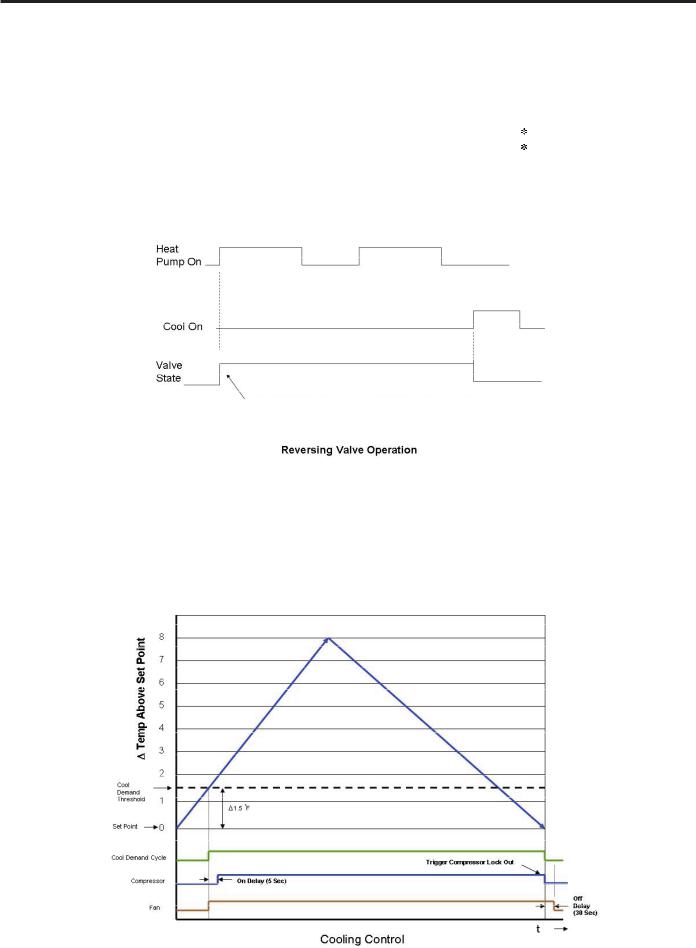
ELECTRONIC CONTROL SEQUENCE OF OPERATION
Compressor and Reversing Valve Control
Active Mode |
Compressor |
Reversing Valve State |
Cooling |
On |
De-Energized |
Heat - Heat Pump |
On |
Energized |
Heat - Electric |
Off |
|
Fan Only |
Off |
|
* The Reversing valve stays in the last state until a call for heat or cooling (see figure below)
Compressor Operation:
The reversing valve only changes when required to provide cooling or heat pump. The RV valve stays in it's last state until required to change.
Cooling Mode
Once the ambient temperature rises past the cool demand threshold (Cool Set Point + 1.5 ˚F) (see figure below), and the compressor is not locked out, the cooling cycle begins. As shown in the figure below, the fan is started 5 seconds prior to the compressor. Once the ambient temperature has been lowered to the cool set point (Cool Set Point minus
.25 ˚F), the cooling cycle starts to terminate by shutting off the compressor. After a 30 seconds delay, the fan is shut off. (See figure below for graphic details)
23
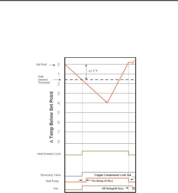
Heating Mode Control Operation
There are two heating methods: Heat Pump and Electric Resistance Heat.
There are 3 types of units that provide heating: Heat Pump Only (Model YS10M10)
Heat Pump with Electric Heat and Cool with Electric Heat.
Heat Control Operation Heat Pump Only
Once the ambient temperature falls below the Heating Demand Threshold
(1.5 ˚F Below the Heat Set Point Temperature), the heating cycle begins. The fan is turned on 5 seconds later. Once the ambient temperature has been raised to the Heat Satisfied Point (Set point + .25 ˚F), the compressor is turned off. The fan is turned off 30 seconds later. The figure below illustrates the basic heat pump operation.
Heat Control (Heat Pump Only)
24
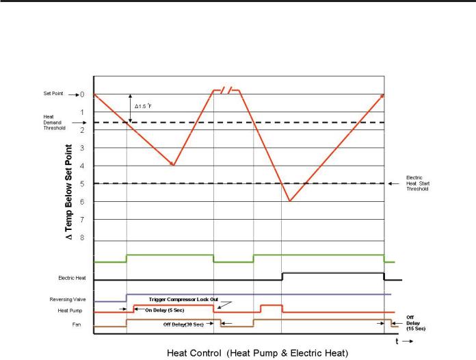
Heat Pump With Electric Heat Operation
This heating is more complex due to the possibility of two heating methods. If the ambient indoor temperature is below the heat demand threshold (1.5˚F below the heat set point temperature), and the compressor is not locked out, turn on compressor. If the ambient indoor temperature is 0.25˚F above the heat set point turn off the compressor.
If the compressor is locked out & electric heat is available:
1.Turn on the electric heat until the compressor is not locked out.
2.After lockout, turn off the electric heat, wait 5 seconds, then turn on the compressor.
If Electric Heat is Available
After the Heat button is initially pressed, the unit will run the electric heater until the initial set point is satisfied (Hot Start Feature). After the initial start, the unit will switch to Heat Pump heat and decide between Heat Pump heat and Electric heat based on the following two monitored conditions:
Condition 1
If the outdoor coil temperature sensor drops to 30 ˚F or less for 2 consecutive minutes, the unit will switch to electric heat if available. Thereafter, the unit will switch back to Heat Pump heat if the outdoor coil temperature sensor rises to 45 ˚F or greater.
If Electric Heat is not available (out of order) and the outdoor coil temperature sensor drops to 30 ˚F or less for 2 consecutive minutes, then the compressor and fan will turn off. Thereafter, the unit will switch back to Heat Pump heat if the outdoor coil temperature rises to 45 ˚F or greater.
25

Heat Pump With Electric Heat Operation (Continued)
Condition 2
If the (delta) (set point temperature minus the ambient indoor temperature) is greater than 5 ˚F, then the unit will switch to electric heat, if available. The unit will continue to operate with electric heat until the heat demand is satisfied. Note that the electric heat switches on after the temp passes 5°F and the heat pump switches off. Also note that the electric heat will run until the heat demand is satisfied. When another heat demand cycle is initiated, the heat pump will run unless the
temp is greater than the electric heat threshold.
Emergency Heat
If a compressor fails in the heating season, the Emergency Heat allows the user to override the Heat Pump and heat with electric heat only. This is controlled via the user interface (See the User Menu Functions page 12).
Note that if heat is the first demand cycle (demand cycle = call for heat or call for cooling) after power restoration, the control system will run electric heat for the entire cycle if the unit is equipped with electric heat.
Electric Heat Operation in Cool with Electric Heat Units
When in the Heat mode, with and without Fan Mode Auto (Fan cycling):
If the indoor ambient temperature is below the Heat Demand Threshold (Heat Set Point minus 1.5 ˚F), turn on electric heat. If Ambient is 0.3 ˚F above the Heat Set Point turn off the electric heat.
System Mode Auto
This mode provides automatic change over between cool and heat. The auto mode runs based on the room ambient temperature vs. the Demand Thresholds. It is only available in Heat-Cool Unit.
Notes:
The Heat Demand Threshold and the Cool Demand Threshold values are derived from the Auto Set Point in the Auto Mode (refer to page 22). There is a buffer zone as shown in figure , where no heating or cooling is allowed to occur. It is critical that the Cool Demand Threshold be greater than the Heat Demand Threshold by a minimum of 3° while in the Auto System Mode. For example, if a user enters a value for the Auto Cooling Set Point that violates the minimum 3° rule, the Auto Heating Set Point will adjust accordingly. This buffer zone (BAND) can be manually adjusted from 3 to 10° (see the BAND section page 13).
When programming the schedule, the user has the flexibility to enter the schedule automatic set point cooling (SASPC) and the schedule automatic set point heating (SSPH) set points directly. These values are monitored to ensure that they do not violate the minimum 3° rule. If a violation is detected, the opposite set point will adjust to compensate. The individual heating and cooling rules apply to the auto mode.
Automatic Change Over Delay (Cool with Heat Units)
The change over delay ensures that any system heating or cooling over shoot does not trigger an opposite demand cycle. The change over delay = 15 min. This timer blocks the opposite demand cycle from running until the timer expires. As an example, if the last demand was a cool cycle, and another cool cycle is requested, the timer will not block the request.
However, if the last demand cycle was a cool cycle, and heat cycle is requested, the timer will block the request until the change over delay is expired.
26
 Loading...