


 MANUAL
MODE D’EMPLOI
 Español Français English
MW09Y3H
MW12Y3H
MR09Y3H
MR12Y3H
CONSERVEZ CE MODE D'EMPLOI
POUR RÉFÉRENCE ULTÉRIEUR


 9332280005-01
CONTENTS
....................................SAFETY PRECAUTIONS |
En-1 |
.........................MINIMUM HEAT OPERATION |
En-11 |
FEATURES AND FUNCTIONS ........................... |
En-2 |
ECONOMY OPERATION ................................... |
En-11 |
NAME OF PARTS ................................................ |
En-3 |
SWING OPERATION ......................................... |
En-12 |
PREPARATION .................................................... |
En-5 |
COIL DRY OPERATION ..................................... |
En-12 |
OPERATION ........................................................ |
En-6 |
MANUAL AUTO OPERATION .......................... |
En-12 |
TIMER OPERATION ............................................ |
En-8 |
CLEANING AND CARE ..................................... |
En-13 |
SLEEP TIMER OPERATION ................................ |
En-9 |
TROUBLESHOOTING ....................................... |
En-14 |
ADJUSTING THE DIRECTION OF |
|
OPERATING TIPS .............................................. |
En-15 |
AIR CIRCULATION ........................................... |
En-10 |
SPECIFICATION ................................................ |
En-16 |
|
|
|
|
SAFETY PRECAUTIONS
DANGER!
CAUTION!
●Do not attempt to install this air conditioner by yourself.
●This air conditioner contains no user-serviceable parts. Always consult authorized service personnel for repairs.
●When moving, consult authorized service personnel for disconnection and installation of the air conditioner.
●Do not become excessively chilled by staying for many hours in the direct cooling airflow.
●Do not insert fingers or objects into the outlet port or intake grille.
●Do not start and stop air conditioner operation by disconnecting the power supply cord and so on.
●Take care not to damage the power supply cord.
●In the event of a malfunction (burning smell, etc.), immediately stop operation, turn off the breaker, and consult authorized service personnel.
●If the power supply cord of this appliance is damaged, it should only be replaced by the authorized service personal, since special purpose tools and specified cord are required.
●Provide occasional ventilation during use.
●Do not direct airflow at fireplaces or heating apparatus.
●Do not climb on, or place objects on, the air conditioner.
●Do not hang objects from the indoor unit.
●Do not set flower vases or water containers on top of air conditioners.
●Do not expose the air conditioner directly to water.
●Do not operate the air conditioner with wet hands.
●Do not pull power supply cord.
●Turn off power supply when not using the indoor unit for extended periods.
●Check the condition of the installation stand for damage.
●Do not place animals or plants in the direct path of the airflow.
●Do not drink the water drained from the air conditioner.
●Do not use in applications involving the storage of foods, plants or animals, precision equipment, or art works.
●Connection valves become hot during Heating; handle with care.
●Do not apply any heavy pressure to radiator fins.
●Operate only with air filters installed.
●Do not block or cover the intake grille and outlet port.
●Ensure that any electronic equipment is at least one meter away from either the indoor or outdoor units.
●Avoid installing the air conditioner near a fireplace or other heating apparatus.
●When installing the indoor and outdoor unit, take precautions to prevent access to infants.
●Do not use inflammable gases near the air conditioner.
En-1
FEATURES AND FUNCTIONS
INVERTER
At the start of operation, a large power is used to bring the room quickly to the desired temperature. Afterward, the air conditioner automatically switches to a low power setting for economic and comfortable operation.
COIL DRY OPERATION
The Indoor unit can be dried by pressing the COIL DRY button on the Remote Control Unit so as to avoid going moldy and restrain the breed of bacterium.
AUTO CHANGEOVER
The operation mode (cooling, dry, heating) is switched automatically to maintain the set temperature, and the temperature is kept constant at all times.
MINIMUM HEAT OPERATION
The room temperature can be maintained at 50 °F so as to prevent the room temperature from falling too far.
SWING OPERATION
The Air Flow Direction Louvers swings automatically up and down so that the air speeds to every nook and corner of your room.
REMOVABLE INTAKE GRILLE
The indoor unit’s Intake Grille can be removed for easy cleaning and maintenance.
MILDEW-RESISTANT FILTER
The AIR FILTER has been treated to resist mildew growth, thus allowing cleaner use and easier care.
SUPER QUIET OPERATION
When the FAN button is used to select QUIET, the indoor unit begins super-quiet operation; the indoor unit’s airflow is reduced to produce quieter operation.
PROGRAM TIMER
The program timer allows you to integrate OFF timer and ON timer operations in a single sequence. The sequence can involve one transition from OFF timer to ON timer, or from ON timer to OFF timer, within a twenty-four hour period.
SLEEP TIMER
When the SLEEP button is pressed during Heating mode, the indoor unit’s thermostat setting is gradually lowered during the period of operation; during cooling mode, the thermostat setting is gradually raised during the period of operation. When the set time is reached, the indoor unit automatically turns off.
WIRELESS REMOTE CONTROL UNIT
The Wireless Remote Control Unit allows convenient control of indoor unit operation.
WIRED REMOTE CONTROL UNIT (OPTION)
The optional wired remote control unit (model No.: UTY-RNBLU) can be used.
It requires the Communication Box Kit (Model Name: UTY-XCBXZ1) to connect the wired remote control.
When you use remote control unit, there are following different points as compared with using wireless remote control unit.
[The additional functions for wired ones]
•Weekly timer
•Temperature set back timer
[The restricted functions for wired ones]
•Horizontal Airflow Direction and swing
•MAINTENANCE
And you can use both wired and wireless remote control unit simultaneously. (But function is limited.)
[The restricted function for wireless ones]
•SLEEP
•TIMER
•COIL DRY
•MIN. HEAT
En-2

NAME OF PARTS
Fig. 1
|
a-8 |
|
a-9 |
|
a-1 |
a-10 a-11 a-12 |
a-3 |
a-13 |
|
Fig. 5
a-14 
 a-16
a-16
a-15
a-17
a-11 |
a-2 |
Fig.2 |
a-3 |
|
OPERATION |
a-5 |
TIMER |
a-6 |
COIL DRY |
a-7 |
|
a-4 |
Fig.3 |
|
a-8 |
|
Fig.4
Fig. 6
b-2 b-3
b-4 b-5
b-6
b-7 b-14
 b-1
b-1
b-8 b-9 b-10
b-11
b-12
b-16 b-13 b-15
c-1 |
|
|
|
|
|
|
|
|||||
c-7 |
|
|
|
|
|
|
|
|||||
c-8 |
|
|
|
|
|
|
c-2 |
|||||
c-9 |
|
|
|
|
|
|
|
|
|
|
|
c-3 |
|
|
|
|
|
|
|
|
|
||||
|
|
|
|
|
|
|
|
|||||
|
|
|
|
|||||||||
|
|
|
|
|
|
|
||||||
c-10 |
|
|
|
|
|
|
|
|
|
|
|
c-4 |
|
|
|
|
|
|
|
|
|
|
|
||
|
|
|
|
|
|
|
|
|
|
|
||
|
|
|
|
|
|
|
|
|||||
|
|
|
|
|
|
|
|
|
c-5 |
|||
|
|
|
|
|
|
|
|
|||||
|
|
|
|
|
|
|
||||||
c-11 |
|
|
|
|
|
|
|
|
|
|
|
|
|
|
|
|
|
|
|
|
|
|
|
c-6 |
|
|
|
|
|
|
|
|
|
|
|
|||
|
|
|
|
|
|
|
|
|
|
|
|
|
Fig. 7
To facilitate explanation, the accompanying illustration has been drawn to show all possible indicators; in actual operation, however, the display will only show those indicators appropriate to the current operation.
En-3
 Fig. 1 Indoor Unit
a-1 Operating Control Panel (Fig. 2) a-2 MANUAL AUTO button
●When kept on pressing the MANUAL AUTO button for more than 10 seconds, the forced cooling operation will start.
●The forced cooling operation is used at the time of installation.
Only for authorized service personnel's use.
●When the forced cooling operation starts by any chance, press the START/ STOP button to stop the operation.
a-3 Indicator (Fig. 3)
a-4 Remote Control Signal Receiver
a-5 OPERATION Indicator Lamp (green)
a-6 TIMER Indicator Lamp (orange)
|
● If the TIMER indicator lamp flashes when |
|
the timer is operating, it indicates that a |
|
fault has occurred with the timer setting |
|
(See Page 15 Auto Restart). |
a-7 |
COIL DRY Indicator Lamp (yellow) |
|
|
a-8 |
Intake Grille (Fig. 4) |
a-9 |
Front Panel |
a-10 |
Air Filter |
a-11 |
Airflow Direction Louver |
a-12 |
Right-Left Louver |
|
(behind Airflow Direction Louver) |
a-13 |
Drain Hose |
 Fig. 5 Outdoor Unit
a-14 Intake Port
a-15 Outlet Port
a-16 Pipe Unit
a-17 Drain port (bottom)
 Fig. 6 Remote Control Unit
b-1 Signal Transmitter b-2 MODE button
b-3 MIN. HEAT button
b-4 SET TEMP. button (  /
/  ) b-5 COIL DRY button
b-6 SLEEP button
b-7 TIMER MODE button b-8 FAN button
b-9 START/STOP button b-10 ECONOMY button b-11 SET button
b-12 SWING button
b-13 TIMER SET (  /
/  ) button b-14 CLOCK ADJUST button b-15 TEST RUN button
●This button is used when installing the air conditioner, and should not be used under normal conditions, as it will cause the indoor unit’s thermostat function to operate incorrectly.
●If this button is pressed during normal operation, the indoor unit will switch to test operation mode, and the Indoor Unit’s OPERATION Indicator Lamp and TIMER Indicator Lamp will begin to flash simultaneously.
●To stop the test operation mode, press the START/STOP button to stop the air conditioner.
b-16 RESET button
c-1 Remote Control Unit Display (Fig. 7) c-2 Transmit Indicator
c-3 Fan Speed Display c-4 SWING Display
c-5 Timer Mode Display c-6 Clock Display
c-7 Temperature SET Display c-8 ECONOMY Display
c-9 Operation Mode Display c-10 COIL DRY Display
c-11 SLEEP Display
En-4
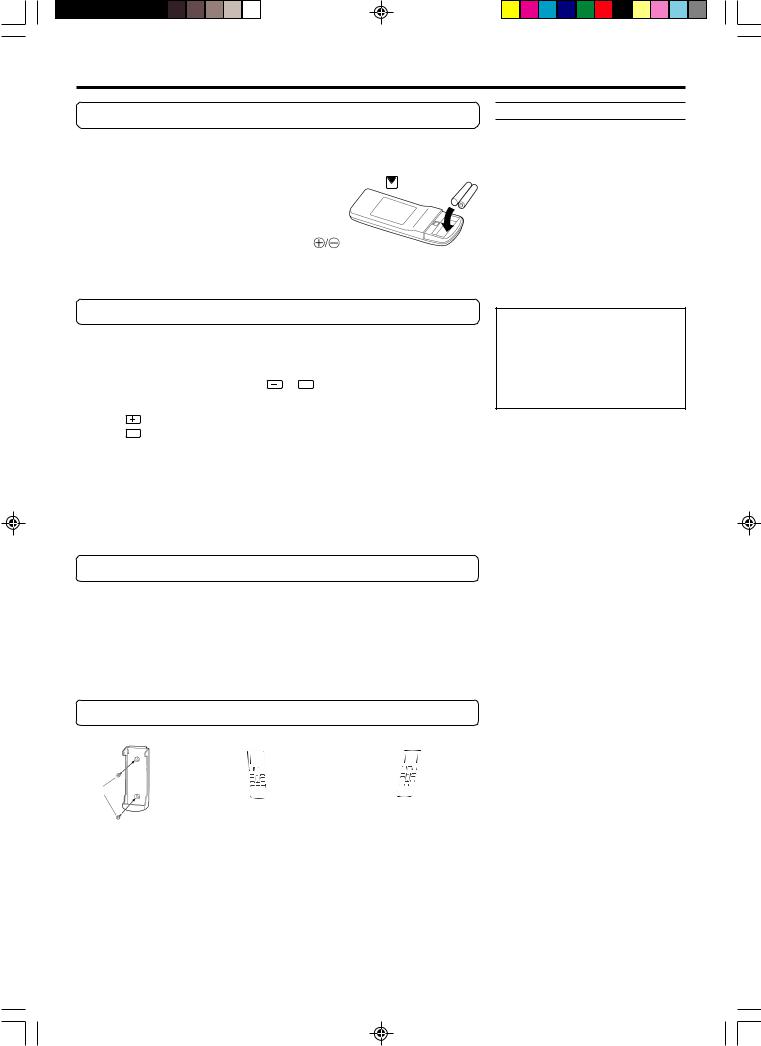
PREPARATION
Load Batteries (AAA/R03/LR03 × 2)
1 |
Press and slide the battery compartment lid on the re- |
||||||
verse side to open it. |
|
|
|
|
|||
|
Slide in the direction of the arrow while pressing the mark. |
||||||
2 |
Insert batteries. |
|
|
|
|
||
Be sure to align the battery polarities ( |
) correctly. |
||||||
3 |
Close the battery compartment lid. |
||||||
Set the Current time |
|
|
|
|
|||
1 |
Press the CLOCK ADJUST button (Fig. 6 b-14). |
||||||
Use the tip of a ball-point pen or other small object to press the button. |
|||||||
2 |
Use the TIMER SET ( |
/ |
|
|
) buttons (Fig. 6 b-13) to |
||
|
|
||||||
adjust the clock to the current time. |
|||||||
|
|
|
button: Press to advance the time. |
|
|||
|
|
|
button: Press to reverse the time. |
|
|||
|
|
|
|
||||
|
(Each time the buttons are pressed, the time will be advanced/reversed in |
||||||
|
five-minute increments; hold the buttons depressed to change the time |
||||||
|
quickly in ten-minute increments.) |
|
|||||
3 |
Press the CLOCK ADJUST button (Fig. 6 b-14) again. |
||||||
This completes the time setting and starts the clock. |
|||||||
To Use the Remote Control Unit
●The Remote Control Unit must be pointed at signal receiver (Fig. 3 a-4) to operate correctly.
●Operating Range: About 23ft (7 meters).
●When a signal is properly received by the indoor unit, a beeping sound will be heard.
●If no beep is heard, press the Remote Control Unit button again.
Remote Control Unit Holder
Insert |
Slide up |
|
Press in |
Pull out |
|
Screws |
||
|
||
1 Mount the Holder. 2 Set the Remote Control |
3 To remove the Remote |
|
Unit. |
Control Unit (when use at |
|
|
hand). |
 CAUTION!
●Take care to prevent infants from accidentally swallowing batteries.
●When not using the Remote Control Unit for an extended period, remove the batteries to avoid possible leakage and damage to the unit.
●If leaking battery fluid comes in contact with your skin, eyes, or mouth, immediately wash with copious amounts of water, and consult your physician.
●Dead batteries should be removed immediately and disposed of properly, either in a battery collection receptacle or to the appropriate authority.
●Do not attempt to recharge dry batteries.
Never mix new and used batteries, or batteries of different types.
Batteries should last about one year under normal use. If the Remote Control Unit’s operating range becomes appreciably reduced, replace the batteries and press the RESET button with the tip of a ballpoint pen or other small object.
En-5
 Loading...