


Friedrich H)A12K25L, H)A12K50L, H)A12K34L, H)A09K50L, H)A24K34L User Manual
...S e r v i c e M a n u a l – R 4 1 0 A M o d e l s

 A Series (Electronic Controls)
Single Package Vertical Air Conditioning System
L Suffix Models
V(E, H)A09K25L-* |
V(E, H)A09K34L-* |
V(E, H)A09K50L-* |
V(E, H)A12K25L-* |
V(E, H)A12K34L-* |
V(E, H)A12K50L-* |
V(E, H)A18K25L-* |
V(E, H)A18K34L-* |
V(E, H)A18K25L-* |
V(E, H)A24K25L-* |
V(E, H)A24K34L-* |
V(E, H)A24K50L-* |
V(E, H)A24K75L-* |
V(E, H)A24K10L-* |
|
VPK-ServMan-L (1-10) |
*Last Digit May Vary |

INTRODUCTION
This service manual is designed to be used in conjunction with the installation manuals provided with each unit.
This service manual was written to assist the professional HVAC service technician to quickly and accurately diagnose and repair any malfunctions of this product.
This manual, therefore, will deal with all subjects in a general nature. (i.e. All text will pertain to all models).
IMPORTANT: It will be necessary for you to accurately identify the unit you are servicing, so you can be certain of a proper diagnosis and repair.
(See Unit Identification.)
TECHNICAL SUPPORT
CONTACT INFORMATION
FRIEDRICH AIR CONDITIONING CO.
Post Office Box 1540 · San Antonio, Texas 78295-1540
4200 N. Pan Am Expressway · San Antonio, Texas 78218-5212 (210) 357-4400 · 1-800-541-6645 · FAX (210) 357-4490 www.friedrich.com
Printed in the U.S.A.
Table of Contents
Important Safety Information ........................................... |
2-4 |
Introduction ......................................................................... |
4 |
Vert-I-Pak Model Number Identification Guide ................... |
5 |
Serial Number Identification Guide .................................... |
5 |
Chassis Specifications ....................................................... |
6 |
Extended Cooling Performance ......................................... |
7 |
Electrical Requirements ..................................................... |
8 |
Remote Thermostat and Low Voltage Control .............. |
9-10 |
V-PAK Electronic Control Board Features ........................ |
11 |
Electronic Control Configuration ....................................... |
12 |
Electronic Control Error Code |
|
Diagnostics/Test Mode ................................................. |
12-13 |
Electronic Control Features .............................................. |
14 |
Checking External Static Pressure ................................... |
15 |
Checking Approximate Airflow .......................................... |
16 |
Airflow Charts .................................................................... |
16 |
Components Testing .................................................... |
17-18 |
Refrigeration Sequence of Operation ............................... |
19 |
Service ............................................................................. |
20 |
Sealed Refrigeration System Repairs .............................. |
21 |
Refrigerant Charging ........................................................ |
21 |
Method Of Charging ......................................................... |
22 |
Undercharged Refrigerant Systems ............................ |
22-23 |
Overcharged Refrigerant Systems ................................... |
23 |
Restricted Refrigerant Systems ....................................... |
23 |
Capillary Tube Systems/Check Valve .......................... |
24 |
Reversing Valve — Description/Operation .................. |
25 |
Testing Coil .................................................................. |
25 |
Checking Reversing Valves .................................... |
25-26 |
Reversing Valve |
|
Touch Testing Heating/Cooling Cycle ......................... |
26 |
Procedure For Changing Reversing Valve ............. |
26-27 |
Compressor Checks .................................................... |
27 |
Locked Rotor Voltage Test .......................................... |
27 |
Single Phase Connections ......................................... |
27 |
Determine Locked Rotor Voltage ............................... |
27 |
Locked Rotor Amperage Test ...................................... |
27 |
Single Phase Running & Locked Rotor Amperage ..... |
27 |
Checking the Overload ........................................... |
27-28 |
External Overload ........................................................ |
28 |
Compressor Single Phase Resistance Test ................ |
28 |
Compressor Replacement ..................................... |
29-30 |
Routine Maintenance ................................................... |
30 |
9-18 Electrical Troubleshooting Chart – Cooling ......... |
31 |
2-Ton Electrical Troubleshooting Chart – Cooling ....... |
32 |
Electrical Troubleshooting Chart – Heat Pump ........... |
33 |
Refrigerant System Diagnosis – Cooling .................... |
34 |
Refrigerant System Diagnosis – Heating .................... |
34 |
Electrical and Thermostat Wiring Diagrams ........... |
35-40 |
Technical Service Data ................................................ |
41 |
1
IMPORTANT SAFETY INFORMATION
The information contained in this manual is intended for use by a qualified service technician who is familiar with the safety procedures required for installation and repair, and who is equipped with the proper tools and test instruments required to service this product.
Installation or repairs made by unqualified persons can result in subjecting the unqualified person making such repairs as well as the persons being served by the equipment to hazards resulting in injury or electrical shock which can be serious or even fatal.
Safety warnings have been placed throughout this manual to alert you to potential hazards that may be encountered. If you install or perform service on equipment, it is your responsibility to read and obey these warnings to guard against any bodily injury or property damage which may result to you or others.
Your safety and the safety of others are very important.
We have provided many important safety messages in this manual and on your appliance. Always read and obey all safety messages.
This is a safety Alert symbol.
This symbol alerts you to potential hazards that can kill or hurt you and others.
All safety messages will follow the safety alert symbol with the word “WARNING” or “CAUTION”. These words mean:

 WARNING

 CAUTION
You can be killed or seriously injured if you do not follow instructions.
You can receive minor or moderate injury if you do not follow instructions.
All safety messages will tell you what the potential hazard is, tell you how to reduce the chance of injury, and tell you what will happen if the instructions are not followed.
A message to alert you of potential property damage will have the
NOTICE word “NOTICE”. Potential property damage can occur if instructions are not followed.
PERSONAL INJURY OR DEATH HAZARDS
ELECTRICAL HAZARDS:
•Unplug and/or disconnect all electrical power to the unit before performing inspections, maintenance, or service.
•Make sure to follow proper lockout/tag out procedures.
•Always work in the company of a qualified assistant if possible.
•Capacitors, even when disconnected from the electrical power source, retain an electrical charge potential capable of causing electric shock or electrocution.
•Handle, discharge, and test capacitors according to safe, established, standards, and approved procedures.
•Extreme care, proper judgment, and safety procedures must be exercised if it becomes necessary to test or troubleshoot equipment with the power on to the unit.
2
•Do not spray or pour water on the return air grille, discharge air grille, evaporator coil, control panel, and sleeve on the room side of the air conditioning unit while cleaning.
•Electrical component malfunction caused by water could result in electric shock or other electrically unsafe conditions when the power is restored and the unit is turned on, even after the exterior is dry.
•Never operate the A/C unit with wet hands.
•Use air conditioner on a single dedicated circuit within the specified amperage rating.
•Use on a properly grounded outlet only.
•Do not remove ground prong of plug.
•Do not cut or modify the power supply cord.
•Do not use extension cords with the unit.
•Follow all safety precautions and use proper and adequate protective safety aids such as: gloves, goggles, clothing, adequately insulated tools, and testing equipment etc.
•Failure to follow proper safety procedures and/or these warnings can result in serious injury or death.
REFRIGERATION SYSTEM HAZARDS:
•Use approved standard refrigerant recovering procedures and equipment to relieve pressure before opening system for repair.
•Do not allow liquid refrigerant to contact skin. Direct contact with liquid refrigerant can result in minor to moderate injury.
•Be extremely careful when using an oxy-acetylene torch. Direct contact with the torch’s flame or hot surfaces can cause serious burns.
•Make sure to protect personal and surrounding property with fire proof materials.
•Have a fire extinguisher at hand while using a torch.
•Provide adequate ventilation to vent off toxic fumes, and work with a qualified assistant whenever possible.
•Always use a pressure regulator when using dry nitrogen to test the sealed refrigeration system for leaks, flushing etc.
•Make sure to follow all safety precautions and to use proper protective safety aids such as: gloves, safety glasses, clothing etc.
•Failure to follow proper safety procedures and/or these warnings can result in serious injury or death.
MECHANICAL HAZARDS:
•Extreme care, proper judgment and all safety procedures must be followed when testing, troubleshooting, handling, or working around unit with moving and/or rotating parts.
•Be careful when, handling and working around exposed edges and corners of sleeve, chassis, and other unit components especially the sharp fins of the indoor and outdoor coils.
•Use proper and adequate protective aids such as: gloves, clothing, safety glasses etc.
•Failure to follow proper safety procedures and/or these warnings can result in serious injury or death.
3
PROPERTY DAMAGE HAZARDS
FIRE DAMAGE HAZARDS:
•Read the Installation/Operation Manual for this air conditioning unit prior to operating.
•Use air conditioner on a single dedicated circuit within the specified amperage rating.
•Connect to a properly grounded outlet only.
•Do not remove ground prong of plug.
•Do not cut or modify the power supply cord.
•Do not use extension cords with the unit.
•Failure to follow these instructions can result in fire and minor to serious property damage.
WATER DAMAGE HAZARDS:
•Improper installation maintenance, or servicing of the air conditioner unit, or not following the above Safety Warnings can result in water damage to personal items or property.
•Insure that the unit has a sufficient pitch to the outside to allow water to drain from the unit.
•Do not drill holes in the bottom of the drain pan or the underside of the unit.
•Failure to follow these instructions can result in result in damage to the unit and/or minor to serious property damage.
4

|
Model Identification Guide |
|
||||||||
|
|
|
|
|
|
|
|
|
|
|
MODEL NUMBER |
|
V |
E |
A |
24 |
K |
50 |
RT |
L |
|
SERIES |
|
|
|
|
|
|
|
|
|
ENGINEERING CODE |
V=Vertical Series |
|
|
|
|
|
|
|
|
|
|
|
|
|
|
|
|
|
|
|
|
|
|
|
|
|
|
|
|
|
|
|
|
E=Cooling with or without electric heat |
|
|
|
|
|
|
OPTIONS |
|||
H=Heat Pump |
|
|
|
|
|
|
|
|
|
|
|
|
|
|
|
|
|
|
|
RT = Standard Remote Operation |
|
DESIGN SERIES |
|
|
|
|
|
|
|
|
|
SP = Seacoast Protected |
A = 32" and 47" Cabinet |
|
|
|
|
|
|
|
|
|
|
|
|
|
|
|
|
|
|
|
|
|
|
|
|
|
|
|
|
|
|
|
|
NOMINAL CAPACITY |
|
|
|
|
|
|
|
|
|
ELECTRIC HEATER SIZE |
A-Series (Btu/h) |
|
|
|
|
|
|
|
|
|
A-Series |
09 = 9,000 |
|
|
|
|
|
|
|
|
|
00 = No electric heat |
12 = 12,000 |
|
|
|
|
|
|
|
|
|
25 = 2.5 KW |
18 = 18,000 |
|
|
|
|
|
|
|
|
|
34 = 3.4 KW |
24 = 24,000 |
|
|
|
|
|
|
|
|
|
50 = 5.0 KW |
|
|
|
|
|
|
|
|
|
|
75 = 7.5 KW |
VOLTAGE |
|
|
|
|
|
|
|
|
|
|
|
|
|
|
|
|
|
|
|
10 = 10 KW |
|
K = 208/230V-1Ph-60Hz |
|
|
|
|
|
|
|
|
|
|
|
|
|
|
|
|
|
|
|
|
|
|
|
|
|
|
|
|
|
|
|
|
VPAK Serial Number Identification Guide
SERIAL NUMBER |
|
A |
K |
A |
N |
00001 |
|
YEAR MANUFACTURED |
|
|
|
|
PRODUCTION RUN NUMBER |
||
LJ = 2009 |
AE = 2015 |
|
|
|
|
|
|
AK = 2010 |
AF = 2016 |
|
|
|
|
PRODUCT LINE |
|
AA = 2011 |
AG = 2017 |
|
|
|
|
||
AB = 2012 |
AH = 2018 |
|
|
|
|
N = VPAK |
|
AC = 2013 |
AJ = 2019 |
|
|
|
|
|
|
AD = 2014 |
|
|
|
|
|
|
|
|
|
|
|
|
|
|
|
MONTH MANUFACTURED |
|
|
|
|
|
||
A = Jan |
D = Apr |
G = Jul |
K = Oct |
|
|
|
|
B = Feb |
E = May |
H = Aug |
L = Nov |
|
|
|
|
C = Mar |
F = Jun |
J = Sep |
M = Dec |
|
|
|
|
5

Chassis Specifications
Model 2010 |
VEA09K |
VEA12K |
VEA18K |
VEA24K |
COOLING DATA |
|
|
|
|
COOLING BTUh |
9400/9000 |
11500/11200 |
17000/16500 |
23000/22700 |
POWER (W) |
959 |
1173 |
1888 |
2421 |
EER |
9.8/9.8 |
9.8/9.8 |
9.0/9.0 |
9.5/9.5 |
SENSIBLE HEAT RATIO |
0.74 |
0.72 |
0.70 |
0.70 |
HEAT PUMP DATA |
|
|
|
|
HEATING BTUh |
|
N/A |
|
|
COP @ 47F |
|
N/A |
|
|
HEATING POWER (W) |
|
N/A |
|
|
HEATING CURRENT (A) |
|
N/A |
|
|
ELECTRICAL DATA |
|
|
|
|
VOLTAGE (1 PHASE, 60 Hz) |
230/208 |
230/208 |
230/208 |
230/208 |
VOLT RANGE |
253-198 |
253-198 |
253-198 |
253-198 |
COOLING CURRENT (A) |
4.2/4.4 |
5.2/5.4 |
8.1/8.5 |
10.0/10.4 |
AMPS L.R. |
19.8 |
30 |
42 |
34.8 |
AMPS F.L. |
3.5 |
4.5 |
7.8 |
9.5 |
INDOOR MOTOR (HP) |
1/4 |
1/4 |
1/4 |
1/4 |
INDOOR MOTOR (A) |
1.2 |
1.2 |
1.2 |
1.94 |
OUTDOOR MOTOR (HP) |
|
N/A |
|
1/4 |
OUTDOOR MOTOR (A) |
|
N/A |
|
0.85 |
AIRFLOW DATA |
|
|
|
|
INDOOR CFM* |
300 |
350 |
450 |
610 |
VENT CFM |
60 |
60 |
60 |
60 |
MAX. ESP |
.3" |
.3" |
.3" |
.4" |
PHYSICAL |
|
|
|
|
DIMENSIONS (W x D x H) |
23x23x32 |
23x23x32 |
23x23x32 |
23x23x47 |
NET WEIGHT (LBS) |
114 |
124 |
144 |
167 |
SHIPPING WEIGHT (LBS) |
125 |
135 |
155 |
220 |
R410A CHARGE (oz) |
33.5 |
35.5 |
48 |
65 |
* Normal Value Wet Coil @ .1"ESP.
VHA09K |
VHA12K |
VHA18K |
VHA24K |
|
|
|
|
9200/9000 |
11500/11200 |
17000/16800 |
23000/22800 |
939 |
1186 |
1868 |
2527 |
9.8/9.8 |
9.7/9.7 |
9.1/9.1 |
9.1/9.1 |
0.74 |
0.72 |
0.70 |
0.70 |
|
|
|
|
8500 |
10800 |
16000 |
20000 |
3.0 |
3.0 |
3.0 |
3.0 |
830 |
1055 |
1563 |
1953 |
3.6 |
4.9 |
7.5 |
9.4 |
|
|
|
|
230/208 |
230/208 |
230/208 |
230/208 |
253-198 |
253-198 |
253-198 |
253-198 |
4.1/4.3 |
5.3/5.5 |
8.2/8.5 |
10.6/10.8 |
18.5 |
26 |
42 |
34.8 |
3.5 |
5 |
7.8 |
9.5 |
1/4 |
1/4 |
1/4 |
1/4 |
1.2 |
1.2 |
1.2 |
1.94 |
|
N/A |
|
1/4 |
|
N/A |
|
0.85 |
|
|
|
|
300 |
420 |
450 |
610 |
60 |
60 |
60 |
60 |
.3" |
.3" |
.3" |
.4" |
|
|
|
|
23x23x32 |
23x23x32 |
23x23x32 |
23x23x47 |
114 |
125 |
144 |
167 |
125 |
135 |
155 |
220 |
39 |
42 |
52 |
74 |
ELECTRIC HEAT DATA |
|
|
|
|
|
|
|
|
|
|
VE/VHA09 |
|
|
VE/VHA12 |
|
|
|
HEATER WATTS |
2500/2050 |
3400/2780 |
5000/4090 |
2500/2050 |
3400/2780 |
5000/4090 |
|
|
VOLTAGE |
|
230/208 |
|
|
230/208 |
|
|
|
HEATING BTUh |
8500/7000 |
11600/9500 |
17000/13900 |
8500/7000 |
11600/9500 |
17000/13900 |
|
|
HEATING CURRENT (AMPS) |
10.9/9.9 |
14.8/13.4 |
21.7/19.7 |
10.9/9.9 |
14.8/13.4 |
21.7/19.7 |
|
|
MINIMUM CIRCUIT AMPACITY |
15 |
19.9 |
28.6 |
15 |
19.9 |
28.6 |
|
|
BRANCH CIRCUIT FUSE (AMPS) |
15 |
20 |
30 |
15 |
20 |
30 |
|
|
BASIC HEATER SIZE |
2.5 Kw |
3.4 Kw |
5.0 Kw |
2.5 Kw |
3.4 Kw |
5.0 Kw |
|
|
|
|
|
|
|
|
|
|
|
ELECTRIC HEAT DATA |
|
|
|
|
|
|
|
|
|
|
VE/VHA18 |
|
|
|
VE/VHA24 |
|
|
HEATER WATTS |
2500/2050 |
3400/2780 |
5000/4090 |
2500/2050 |
3400/2780 |
5000/4090 |
7500/6135 |
10000/8180 |
VOLTAGE |
|
230/208 |
|
|
|
230/208 |
|
|
HEATING BTUh |
8500/7000 |
11600/9500 |
17000/13900 |
8500/7000 |
11600/9500 |
17000/13900 |
25598/2093934130/27918 |
|
HEATING CURRENT (AMPS) |
10.9/9.9 |
14.8/13.4 |
21.7/19.7 |
10.9/9.9 |
14.8/13.4 |
21.7/19.7 |
32.6/29.5 |
43.5/39.3 |
MINIMUM CIRCUIT AMPACITY |
15 |
19.9 |
28.6 |
17.2/15.9 |
22.1/20.3 |
30.7/28.1 |
44.3/40.3 |
57.9/52.7 |
BRANCH CIRCUIT FUSE (AMPS) |
15 |
20 |
30 |
25 |
25 |
30 |
45 |
60 |
BASIC HEATER SIZE |
2.5 Kw |
3.4 Kw |
5.0 Kw |
2.5 Kw |
3.4 Kw |
5.0 Kw |
7.5 Kw |
10.0 Kw |
6
Extended Cooling Performance
VEA - EXTENDED COOLING PERFORMANCE
|
|
|
|
|
OUTDOOR DRY BULB TEMP. (DEGREES F AT 40% R.H.) |
|
|
|
|||||||||
|
|
|
75 |
|
|
85 |
|
|
95 |
|
|
105 |
|
|
110 |
|
|
|
|
|
|
|
|
|
|
|
|
|
|
||||||
|
|
|
|
|
INDOOR WET |
BULB TEMP. (DEGREES F AT 80 F D.B.) |
|
|
|
||||||||
|
|
72 |
67 |
62 |
72 |
67 |
62 |
72 |
67 |
62 |
72 |
67 |
62 |
72 |
67 |
62 |
|
|
BTUh |
11054 |
10631 |
9842 |
10528 |
9926 |
9156 |
10114 |
9400 |
8319 |
9475 |
8413 |
7417 |
8954 |
7835 |
6914 |
|
VEA09 |
WATTS |
783 |
795 |
804 |
853 |
861 |
872 |
959 |
959 |
959 |
1037 |
1036 |
1039 |
1084 |
1083 |
1087 |
|
AMPS |
3.5 |
3.5 |
3.5 |
3.7 |
3.8 |
3.8 |
4.2 |
4.20 |
4.2 |
4.5 |
4.5 |
4.5 |
4.7 |
4.7 |
4.7 |
||
|
|||||||||||||||||
|
SHR |
0.51 |
0.69 |
0.93 |
0.52 |
0.71 |
0.95 |
0.52 |
0.74 |
0.95 |
0.53 |
0.78 |
0.96 |
0.55 |
0.81 |
0.95 |
|
|
BTUh |
13524 |
13007 |
12041 |
12880 |
12144 |
11201 |
12374 |
11500 |
10178 |
11592 |
10293 |
9074 |
10954 |
9585 |
8458 |
|
VEA12 |
WATTS |
957 |
972 |
983 |
1043 |
1053 |
1066 |
1173 |
1173 |
1173 |
1268 |
1267 |
1270 |
1325 |
1325 |
1330 |
|
AMPS |
4.3 |
4.3 |
4.4 |
4.6 |
4.7 |
4.7 |
5.2 |
5.20 |
5.2 |
5.6 |
5.6 |
5.6 |
5.9 |
5.9 |
5.9 |
||
|
|||||||||||||||||
|
SHR |
0.49 |
0.67 |
0.90 |
0.50 |
0.70 |
0.92 |
0.51 |
0.72 |
0.92 |
0.52 |
0.76 |
0.93 |
0.53 |
0.79 |
0.93 |
|
|
BTUh |
19992 |
19227 |
17799 |
19040 |
17952 |
16558 |
18292 |
17000 |
15045 |
17136 |
15215 |
13413 |
16193 |
14170 |
12504 |
|
VEA18 |
WATTS |
1541 |
1565 |
1582 |
1678 |
1695 |
1716 |
1888 |
1888 |
1888 |
2041 |
2039 |
2045 |
2133 |
2132 |
2140 |
|
AMPS |
6.7 |
6.7 |
6.8 |
7.2 |
7.2 |
7.3 |
8.1 |
8.10 |
8.1 |
8.7 |
8.7 |
8.7 |
9.1 |
9.1 |
9.1 |
||
|
|||||||||||||||||
|
SHR |
0.48 |
0.65 |
0.88 |
0.49 |
0.68 |
0.89 |
0.49 |
0.70 |
0.90 |
0.50 |
0.74 |
0.90 |
0.52 |
0.76 |
0.9 |
|
|
BTUh |
27048 |
26013 |
24081 |
25760 |
24288 |
22402 |
24748 |
23000 |
20355 |
23184 |
20585 |
18147 |
21908 |
19171 |
16917 |
|
VEA24 |
WATTS |
1976 |
2007 |
2029 |
2152 |
2174 |
2201 |
2421 |
2421 |
2421 |
2617 |
2615 |
2622 |
2736 |
2735 |
2744 |
|
AMPS |
8.3 |
8.3 |
8.4 |
8.9 |
9.0 |
9.0 |
10.0 |
10.00 |
10.1 |
10.8 |
10.8 |
10.8 |
11.3 |
11.3 |
11.3 |
||
|
|||||||||||||||||
|
SHR |
0.48 |
0.65 |
0.88 |
0.49 |
0.68 |
0.89 |
0.49 |
0.70 |
0.9 |
0.5 |
0.74 |
0.9 |
0.52 |
0.76 |
0.9 |
|
|
|
|
|
|
|
|
|
RATING POINT |
|
|
|
|
|
|
|||
|
|
|
|
|
|
|
|
ARI 310/380 |
|
|
|
|
|
|
|||
|
|
|
|
|
|
|
|
|
|
|
|
|
|
|
|
|
|
VHA - EXTENDED COOLING PERFORMANCE |
|
|
|
|
|
|
|
|
|
|
|
||||||
|
|
|
|
|
OUTDOOR DRY BULB TEMP. (DEGREES F AT 40% R.H.) |
|
|
|
|||||||||
|
|
|
75 |
|
|
85 |
|
|
95 |
|
|
105 |
|
|
110 |
|
|
|
|
|
|
|
INDOOR WET |
BULB TEMP. (DEGREES F AT 80 F D.B.) |
|
|
|
||||||||
|
|
72 |
67 |
62 |
72 |
67 |
62 |
72 |
67 |
62 |
72 |
67 |
62 |
72 |
67 |
62 |
|
|
BTUh |
10819 |
10405 |
9632 |
10304 |
9715 |
8961 |
9899 |
9200 |
8142 |
9274 |
8234 |
7259 |
8763 |
7668 |
6767 |
|
VHA09 |
WATTS |
766 |
778 |
787 |
835 |
843 |
854 |
939 |
939 |
939 |
1015 |
1014 |
1017 |
1061 |
1061 |
1064 |
|
AMPS |
3.4 |
3.4 |
3.5 |
3.7 |
3.7 |
3.7 |
4.1 |
4.10 |
4.1 |
4.4 |
4.4 |
4.4 |
4.6 |
4.6 |
4.6 |
||
|
|||||||||||||||||
|
SHR |
0.51 |
0.69 |
0.93 |
0.52 |
0.71 |
0.95 |
0.52 |
0.74 |
0.95 |
0.53 |
0.78 |
0.96 |
0.55 |
0.81 |
0.95 |
|
|
BTUh |
13524 |
13007 |
12041 |
12880 |
12144 |
11201 |
12374 |
11500 |
10178 |
11592 |
10293 |
9074 |
10954 |
9585 |
8458 |
|
VHA12 |
WATTS |
968 |
983 |
994 |
1054 |
1065 |
1078 |
1186 |
1186 |
1186 |
1282 |
1281 |
1284 |
1340 |
1340 |
1344 |
|
AMPS |
4.4 |
4.4 |
4.5 |
4.7 |
4.7 |
4.8 |
5.3 |
5.30 |
5.3 |
5.7 |
5.7 |
5.7 |
6 |
6 |
6 |
||
|
|||||||||||||||||
|
SHR |
0.49 |
0.67 |
0.9 |
0.5 |
0.7 |
0.92 |
0.51 |
0.72 |
0.92 |
0.52 |
0.76 |
0.93 |
0.53 |
0.79 |
0.93 |
|
|
BTUh |
19992 |
19227 |
17799 |
19040 |
17952 |
16558 |
18292 |
17000 |
15045 |
17136 |
15215 |
13413 |
16193 |
14170 |
12504 |
|
VHA18 |
WATTS |
1524 |
1549 |
1565 |
1661 |
1677 |
1698 |
1868 |
1868 |
1868 |
2019 |
2017 |
2023 |
2111 |
2110 |
2117 |
|
AMPS |
6.8 |
6.8 |
6.9 |
7.3 |
7.3 |
7.4 |
8.2 |
8.20 |
8.2 |
8.8 |
8.8 |
8.9 |
9.2 |
9.2 |
9.3 |
||
|
|||||||||||||||||
|
SHR |
0.48 |
0.65 |
0.88 |
0.49 |
0.68 |
0.89 |
0.49 |
0.70 |
0.90 |
0.50 |
0.74 |
0.90 |
0.52 |
0.76 |
0.9 |
|
|
BTUh |
27048 |
26013 |
24081 |
25760 |
24288 |
22402 |
24748 |
23000 |
20355 |
23184 |
20585 |
18147 |
21908 |
19171 |
16917 |
|
VHA24 |
WATTS |
2062 |
2095 |
2118 |
2247 |
2269 |
2297 |
2527 |
2527 |
2527 |
2732 |
2729 |
2737 |
2856 |
2854 |
2864 |
|
AMPS |
8.8 |
8.8 |
8.9 |
9.4 |
9.5 |
9.5 |
10.5 |
10.60 |
10.7 |
11.4 |
11.4 |
11.4 |
11.9 |
11.9 |
12 |
||
|
|||||||||||||||||
|
SHR |
0.48 |
0.65 |
0.88 |
0.49 |
0.68 |
0.89 |
0.49 |
0.70 |
0.90 |
0.50 |
0.74 |
0.90 |
0.52 |
0.76 |
0.9 |
|
|
|
|
|
|
|
|
|
RATING POINT |
|
|
|
|
|
|
|||
|
|
|
|
|
|
|
|
ARI 310/380 |
|
|
|
|
|
|
|||
7
A12K25L, H)A12K50L, H)A12K34L, H)A09K50L, H)A24K34L User Manual")
 WARNING
ELECTRIC SHOCK HAZARD
Turn off electric power before service or installation. All electrical connnections and wiring MUST be installed by a qualified electrician and conform to the National Electrical Code and all local codes which have jurisdiction. Failure to do so can result in personal injury and/or death.
ELECTRICAL REQUIREMENTS
Wire Size
“Use ONLY time delayed fused disconnect or HACR type circuit breaker as indicated on the unit’s rating plate (see sample on this page). Proper current protection to the unit is the responsibility of the owner”.
Unit MUST
All units must be hard wired with properly sized breaker. See nameplate for specific chassis electrical requirements. See Electrical Rating Table below for wire size. Use HACR type breakers to avoid nuisance trips. All field wiring must be done in accordance with NEC and local codes.
Electrical Rating Tables
|
|
|
|
15A |
14 |
20A |
12 |
30A |
10 |
Supply voltage
Supply voltage to the unit should be a nominal 208/230 volts. It must be between 197 volts and 253 volts. Supply voltage to the unit should be checked WITH THE UNIT IN OPERATION. Voltage readings outside the specified range can be expected to cause operating problems. Their cause MUST be investigated and corrected.
Sample Nameplate |
|
|
|
|
|
120524 |
|
|
|
|
|
|
|
|
|
|
|
|
COOLING EQUIPMENT |
|
|
|
|
|
|
E |
|
|
|
|
|
L |
|
|
|
|
|
P |
|
|
|
|
|
M |
|
|
FOLLOWING ITEMS |
|
|
A |
|
|
|
|
|
|
S |
|
|
|
|
OUTDOOR GRILLE |
|
|
|
|
|
|
|
|
|
|
|
|
|
INDOOR GRILLE |
8
Remote Thermostat and Low Voltage Control
Connections
|
Cool Off Heat |
Auto On |
RT5 (Two speed fan) |
RT4 (One speed fan) |
|
Remote Thermostat |
Location |
|
All Friedrich Vert-I-Pak units are factory configured to be controlled by using a 24V single stage remote wall mounted thermostat. The thermostat may be auto or manual changeover as long as the control configuration matches that of the Vert-I-Pak unit.
Manual Changeover Thermostat
For Heat Pump equipped units: a single stage, heat/cool thermostat with a terminal for a reversing valve operation is required. Terminal “B” should be continuously energized in the heat mode and terminal “G” should be energized whenever there is a call for heating or cooling. (Typically, a single stage, heat/cool thermostat designed for use with electric heat systems will meet the above requirements).
NOTICE
DO NOT use a two (2) stage Heat Pump Thermostat. Use of this type of thermostat may result in equipment and/or property damage
To control the unit with a wall-mounted thermostat:
1)Pull the disconnect switch.
2)Unscrew and remove the control box panel.
3)After selecting which side you want to run your thermostat wire through, run the wires through the side hole in the box to reach the connection terminal for the wiring.
4)Make the wire connections, appropriately matching the wires as shown in the wiring diagram.
5)Once each wire is matched and connected, the unit is now controlled by the thermostat.
6)Reattach the control box cover.
The thermostat should not be mounted where it may be affected by drafts, discharge air from registers (hot or cold), or heat radiated from the sun or appliances.
The thermostat should be located about 5 Ft. above the floor in an area of average temperature, with good air
circulation. Close proximity to the return air grille is the best choice.
Mercury bulb type thermostats MUST be level to control temperature accurately to the desired set-point. Electronic digital type thermostats SHOULD be level for aesthetics.
Thermostat Location
NOTE: An improperly operating, or poorly located room thermostat can be the source of perceived equipment problems. A careful check of the thermostat and wiring must be made then to insure that it is not the source of problems.
9

Remote Thermostat and Low Voltage Control
Connections (Continued)
Thermostat Connections
C |
= |
Common Ground |
W |
= |
Call for Heating |
Y |
= |
Call for Cooling |
R |
= |
24V Power from Unit |
GL |
= |
Call for Fan (Low Speed) |
GH |
= |
Call for Fan (High Speed) |
B |
= |
Reversing Valve Energized in heating mode |
*If only one G terminal is present on thermostat, connect to GL for low fan or to GH for high fan operation.
NOTE: It is the installer’s responsibility to ensure that all control wiring connections are made in accordance with the Freidrich installation instructions. Questions concerning proper connections to the unit should be directed to the factory: 210-357-4400.
Desk Control Terminals
The Friedrich VERT-I-PAK has built-in provisions for connection to an external switch to control power to the unit. The switch can be a central desk control system or even a normally open door switch.
For desk control operation, connect one side of the switch to the D1 terminal and the other to the D2 terminal. Whenever the switch closes, the unit operation will stop.
Maximum Wire Length for Desk Control Switch
Wire Size |
Maximum Length |
|
|
#24 |
400 ft. |
|
|
#22 |
600 ft. |
Note: The desk |
|
#20 |
900 ft. |
||
|
|
control system and |
|
#18 |
1500 ft. |
||
switches must be |
|||
#16 |
2000 ft. |
||
field supplied. |
Auxiliary Fan Control
The Smart Center also has the ability to control a 24VAC relay to activate an auxiliary, or transfer, fan. The outputs are listed as F1 and F2 on the control board.
To connect the relay, simply wire one side of the relay to F1 and the other side to F2. Anytime that the fan runs, the terminals will send a 24VAC signal to the relay. The relay must be 24 VAC, 50mA or less.
Note: The relay and auxiliary fans must be field supplied.
10

ELECTRONIC CONTROL BOARD FEATURES
The new Friedrich Vert-I-Pak has state of the art features to improve guest comfort and conserve energy. Through the use of specifically designed control software, Friedrich has accomplished what other Manufacturer’s have only attempted – a quiet, dependable, affordable and easy to use Vert-I-Pak.
Below is a list of standard features on every Friedrich VPAK and their benefit to the owner.
Quiet Start/Stop |
The fan start and stop delays prevent abrupt changes in room acoustics due to the compressor energizing |
|
or stopping immediately. Upon call for cooling or heating the unit fan will run for five seconds prior to en- |
||
Fan Delay |
ergizing the compressor. Also, the fan off delay allows for “free cooling” by utilizing the already cool indoor |
|
|
coil to its maximum capacity by running for 30 seconds after the compressor. |
|
|
|
|
Remote Thermostat |
VPAK units are thermostat controlled. |
|
Operation |
||
|
||
|
|
|
Internal Diagnostic |
The new Friedrich digital VPAK features a self diagnostic program that can alert maintenance to compo- |
|
Program |
nent failures or operating problems. The internal diagnostic program saves properties valuable time when |
|
diagnosing running problems. |
||
|
|
|
Service Error Code |
The self diagnosis program will also store error codes in memory if certain conditions occur and correct |
|
themselves such as extreme high or low operating conditions or activation of the room freeze protection |
||
Storage |
feature. Storing error codes can help properties determine if the unit faced obscure conditions or if an error |
|
|
occurred and corrected itself. |
|
|
|
|
|
When the VPAK senses that the indoor room temperature has fallen to 40°F the unit will cycle on high fan |
|
Room Freeze |
and the electric strip heat to raise the room temperature to 46°F then cycle off again. This feature works |
|
Protection |
regardless of the mode selected and can be turned off. The control will also store the Room Freeze cycle |
|
in the service code memory for retrieval at a later date. This feature ensures that unoccupied rooms do not |
||
|
reach freezing levels where damage can occur to plumbing and fixtures. |
|
|
|
|
Random |
Multiple compressors starting at once can often cause electrical overloads and premature unit failure. |
|
Compressor Restart |
The random restart delay eliminates multiple units from starting at once following a power outage or initial |
|
power up. The compressor delay will range from 180 to 240 seconds. |
||
|
|
|
Digital Defrost |
The new Friedrich VPAK uses a digital thermostat to accurately monitor the outdoor coil conditions to allow |
|
Thermostat |
the heat pump to run whenever conditions are correct. Running the VPAK in heat pump mode save energy |
|
and reduces operating costs. The digital thermostat allows maximization of heat pump run time. |
||
|
|
|
Instant Heat |
Heat pump models will automatically run the electric heater during compressor lock-out to quickly provide |
|
Heat Pump Mode |
heat when initially energized, then return to heat pump mode. This ensures that the room is heated quickly |
|
without the usual delay associated with heat pump units. |
||
|
|
|
Emergency Heat |
In the event of a compressor failure in heat pump mode the compressor may be locked out to provide heat |
|
Override |
through the resistance heater. This feature ensures that even in the unlikely event of a compressor failure |
|
the room temperature can be maintained until the compressor can be serviced. |
||
|
|
|
Desk Control Ready |
All electronic VPAK units have low voltage terminals ready to connect a desk control energy management |
|
system. Controlling the unit from a remote location like the front desk can reduce energy usage and |
||
|
requires no additional accessories at the VPAK. |
|
|
|
|
Indoor Coil Frost |
The frost sensor protects the compressor from damage in the event that airfl ow is reduced or low outdoor |
|
temperatures cause the indoor coil to freeze. When the indoor coil reaches 30°F the compressor is |
||
Sensor |
diabled and the fan continues to operate based on demand. Once the coil temperature returns to 45°F the |
|
|
compressor returns to operation. |
|
|
|
|
Ultra-Quiet Air |
The VPAK series units feature a indoor fan system design that reduces sound levels without |
|
System |
lowering airflow and preventing proper air circulation. |
|
|
|
|
High Efficiency |
The VPAK benefits quality components and extensive development to ensure a quiet, efficient and |
|
dependable unit. |
||
|
||
|
|
|
Rotary Compressor |
High efficiency rotary compressors are used on all Friedrich VPAKs to maximize durability and efficiency. |
|
|
|
|
Auxiliary Fan Ready |
The VPAK features a 24V AC terminal for connection to an auxiliary fan that may be used to transfer air to |
|
adjoining rooms. Auxiliary fans can provide conditioning to multiple rooms. |
||
|
||
|
|
11
Electronic Control Configuration
The adjustable control dip switches are located at the lower left hand portion of the digital Smart Center. The inputs are only visible and accessible with the front cover removed from the Unit.
Factory Dip Switch Configuration
O |
1 |
2 |
3 |
4 |
5 |
6 |
7 |
8 |
|
||||||||
N |
|
|
|
|
|
|
|
|
|
|
|
|
|
|
|
|
|
|
|
|
|
|
|
|
|
|
|
|
|
|
|
|
|
||
|
|
|
|
|
|
|
|
|
|
|
|
|
|
|
|
|
|
|
|
|
|
|
|
|
|
|
|
|
|
|
|
|
|
|
|
|
|
|
|
|
|
|
|
|
|
|
|
|
|
|
|
|
|
Dip Switch Setting
Switches 1-4 ON
Switch 5-7 OFF Switch 8 ON
Room Freeze Protection – Switch 6
Units are shipped from the factory with the room freeze protection disabled. Room Freeze Protection can be switched on at the owner’s preference by moving Dip Switch 6 to ‘ON’. This feature will monitor the indoor room conditions and in the event that the room falls below 40°F the unit will cycle on high fan with the electric heater. This occurs regardless of mode.
Emergency Heat Override – Switch 7
Units are shipped from the factory with the room emergency heat override disabled. In the unlikely event of a compressor failure a heat pump unit may be switched to operate in only the electric heat mode until repairs can be made, by moving Dip Switch 7 to ‘ON’.
Discharge Air Sensor Override – Switch 8
This switch MUST remain in the “ON” position for Vert-I-Pak models, since they do not use a discharge air sensor. If the switch is positioned in the “OFF” position on these models it will result in the erroneous display Error Code 14 indicating that the Discharge air temperature sensor is open or shorted.
Note: In order for the control to recognize “Dip” switch setting changes, the unit must be disconnected from power supply when making any configuration changes.
Electronic Control Error Code
Diagnostics and Test Mode
Error Code Diagnostics
The VPAK electronic control continuously monitors the Vert-I-Pak unit operation and will store error codes if certain conditions are witnessed. In some cases the unit may take action and shut the unit off until conditions are corrected.
To access the error code menu press the ‘HEAT’ and ‘HIGH
FAN’ buttons simultaneously for three seconds. If error codes are present they will be displayed. If multiple codes exist you can toggle between error codes using the temp up ▲button. To clear all codes press the temp down ▼button for three seconds while in the error code mode. To exit without losing codes press the ‘Low Fan’ button.
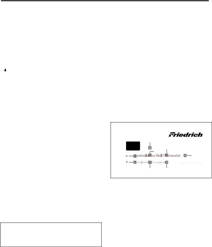
Button Location for Vert-I-Pak Models
With the remote thermostat escutcheon installed, the button locations to access the diagnostics mode can be located as shown below.
Cool |
|
|
High fan |
|
Heat |
Temp |
Power |
Temp |
|
Fan only |
Low fan |
*Heat and high fan - access error codes
*Temp up ▲ and temp down ▼ - toggle between error codes
*Low fan - exit error code mode without losing stored error codes.
*Temp down ▼ - clears all error codes
NOTE: Hold buttons down for three seconds.
12
 Loading...