


H)A09K25
Service Manual
A SERIES
Single Package
Vertical Air Conditioning System
A – H Suffi x Models
MODELS
V(E,H)A09K25*** V(E,H)A09K34*** V(E,H)A09K50***
V(E,H)A12K25*** V(E,H)A12K34*** V(E,H)A12K50***
V(E,H)A18K25*** V(E,H)A18K34*** V(E,H)A18K25***
V(E,H)A24K25*** V(E,H)A24K34*** V(E,H)A24K50***
V(E,H)A24K75*** V(E,H)A24K10*** V(E,H)A24K00***
VPSERVMN (4-05)
*** Digits vary with model.

Table of Contents
Introduction ......................................................................3
Vert-I-Pak Model Number Identifi cation Guide ..............4
Serial Number Identifi cation Guide .................................4
H Suffi x Chassis Specifi cations ......................................5
E and G Suffi x Chassis Specifi cations ............................6
A and D Suffi x Chassis Specifi cations ............................7
Sequence Of Operation ................................................... 8
Electrical Supply ..............................................................9
Supply Circuit ...................................................................9
Supply Voltage .................................................................9
Control (Low) Voltage ......................................................9
Supply Voltage .................................................................9
Electrical Ground .............................................................9
Electrical Rating Tables ...................................................9
Undercharged Refrigerant Systems ..............................17
Overcharged Refrigerant Systems ................................18
Restricted Refrigerant Systems .....................................18
Capillary Tube Systems .................................................19
Reversing Valve — Description/Operation ...................19
Electrical Circuit And Coil ..............................................19
Testing Coil ....................................................................19
Checking Reversing Valves ...........................................20
Touch Testing Heating/Cooling Cycle ..........................20
Procedure For Changing Reversing Valve ....................20
Compressor Checks ......................................................21
Locked Rotor Voltage Test ............................................21
Single Phase Connections ...........................................21
Determine Locked Rotor Voltage .................................21
Electrical Requirements ...................................................9
Room Thermostats ........................................................10
Thermostat Location ......................................................10
Heat Anticipators ..........................................................10
Electrical & Thermostat Wiring Diagrams ................ 11-13
Indoor Blower - Air Flow ................................................14
Condenser Fan Motors ..................................................14
Blower Wheel Inspection ...............................................14
Cooling ........................................................................... 14
Heating (Electric) ..........................................................14
External Static Pressure ................................................14
Checking External Static Pressure ...............................15
Checking Approximate Airfl ow ...................................... 15
Electric Heat Strips ........................................................15
Locked Rotor Amperage Test ........................................21
Single Phase Running & Locked Rotor Amperage .......21
External Overload ..........................................................21
Checking the External Overload ...................................21
Checking the Internal Overload .....................................21
Compressor Single Phase Resistance Test .................22
Compressor Replacement .............................................22
Capacitors ...................................................................... 23
Capacitor Check With Capacitor Analyzer ....................23
Capacitor Connections ..................................................23
Emergency Heat Switch ................................................24
Wiring Diagram Index .............................................. 25-26
9-18 Electrical Troubleshooting Chart – Cooling .........39
2-Ton Electrical Troubleshooting Chart – Cooling .......40
Airfl ow Charts ................................................................16
Refrigerant Charging .....................................................16
Method Of Charging ......................................................17
2
Refrigerant System Diagnosis – Cooling ......................41
Refrigerant System Diagnosis – Heating ...................... 41
Electrical Troubleshooting Chart –Heat Pump .............42
Introduction
This service manual is designed to be used in conjunction with the installation manuals provided with each air
conditioning system component. Air conditioning systems consist of BOTH an evaporator (indoor section) and a
condenser (outdoor section) in one closed system, and a room thermostat. When so equipped, accessories such as
electric strip heaters are also considered part of the system.
This service manual was written to assist the professional HVAC service technician to quickly and accurately diagnose
and repair any malfunctions of this product.
This manual, therefore, will deal with all subjects in a general nature. (i.e. All text will pertain to all models).
IMPORTANT: It will be necessary for you to accurately identify the unit you are
servicing, so you can be certain of a proper diagnosis and repair.
(See Unit Identifi cation.)
WARNING
The information contained in this manual is intended for use by a qualifi ed service technician who is familiar
with the safety procedures required in installation and repair, and who is equipped with the proper tools and
test instruments.
Installation or repairs made by unqualifi ed persons can result in hazards subjecting the unqualifi ed person
making such repairs to the risk of injury or electrical shock which can be serious or even fatal not only to them,
but also to persons being served by the equipment.
If you install or perform service on equipment, you must assume responsibility for any bodily injury or property
damage which may result to you or others. Friedrich Air Conditioning Company will not be responsible for any
injury or property damage arising from improper installation, service, and/or service procedures.
3
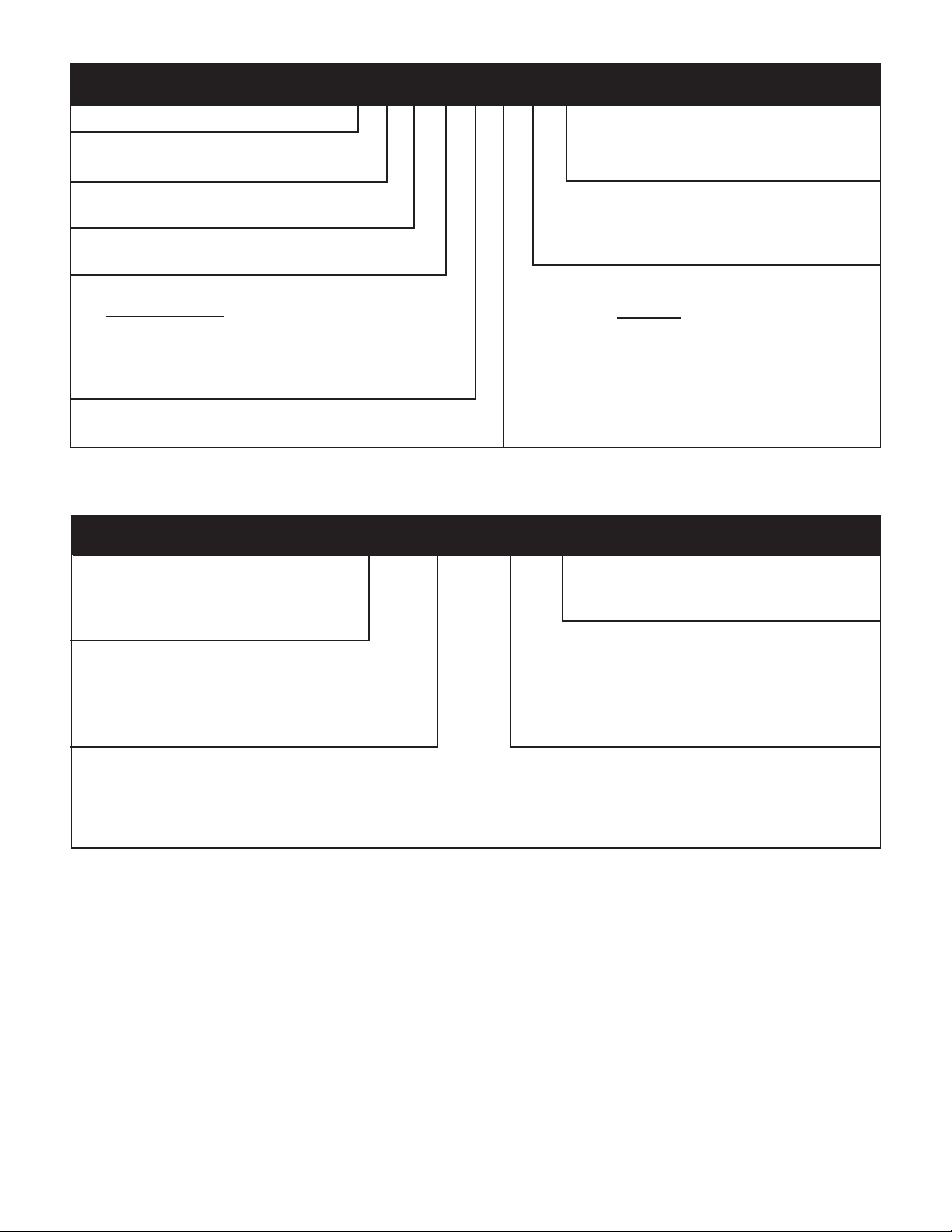
Model Identifi cation Guide
MODEL NUMBER V E A 24 K 50 RT A
SERIES
V=Vertical Series
E=Cooling with or without electric heat
H=Heat Pump
DESIGN SERIES
A = 32" and 47" Cabinet
NOMINAL CAPACITY
A-Series (Btu/h)
09 = 9,000
12 = 12,000
18 = 18,000
24 = 24,000
VOLTAGE
K = 208/230V-1Ph-60Hz
Serial Number Identifi cation Guide
SERIAL NUMBER
L K A V 00001
Decade Manufactured
J = 9 K = Not Used
L = 0
YEAR MANUFACTURED
A = 1 E = 5 J = 9
B = 2 F = 6 K = 0
C = 3 G = 7
D = 4 H = 8
PRODUCTION RUN NUMBER
PRODUCT LINE
R = RAC
P = PTAC
E = EAC
V = VPAK
H = SPLIT
EN GI NEER ING CODE
OPTIONS
RT = Stan dard Re mote Op er a tion
SP = Sea coast Pro tect ed
ELECTRIC HEATER SIZE
A-Series
00 = No electric heat
25 = 2.5 KW
34 = 3.4 KW
50 = 5.0 KW
75 = 7.5 KW
10 = 10 KW
MONTH MANUFACTURED
A = Jan D = Apr G = Jul K = Oct
B = Feb E = May H = Aug L = Nov
C = Mar F = Jun J = Sep M = Dec
4
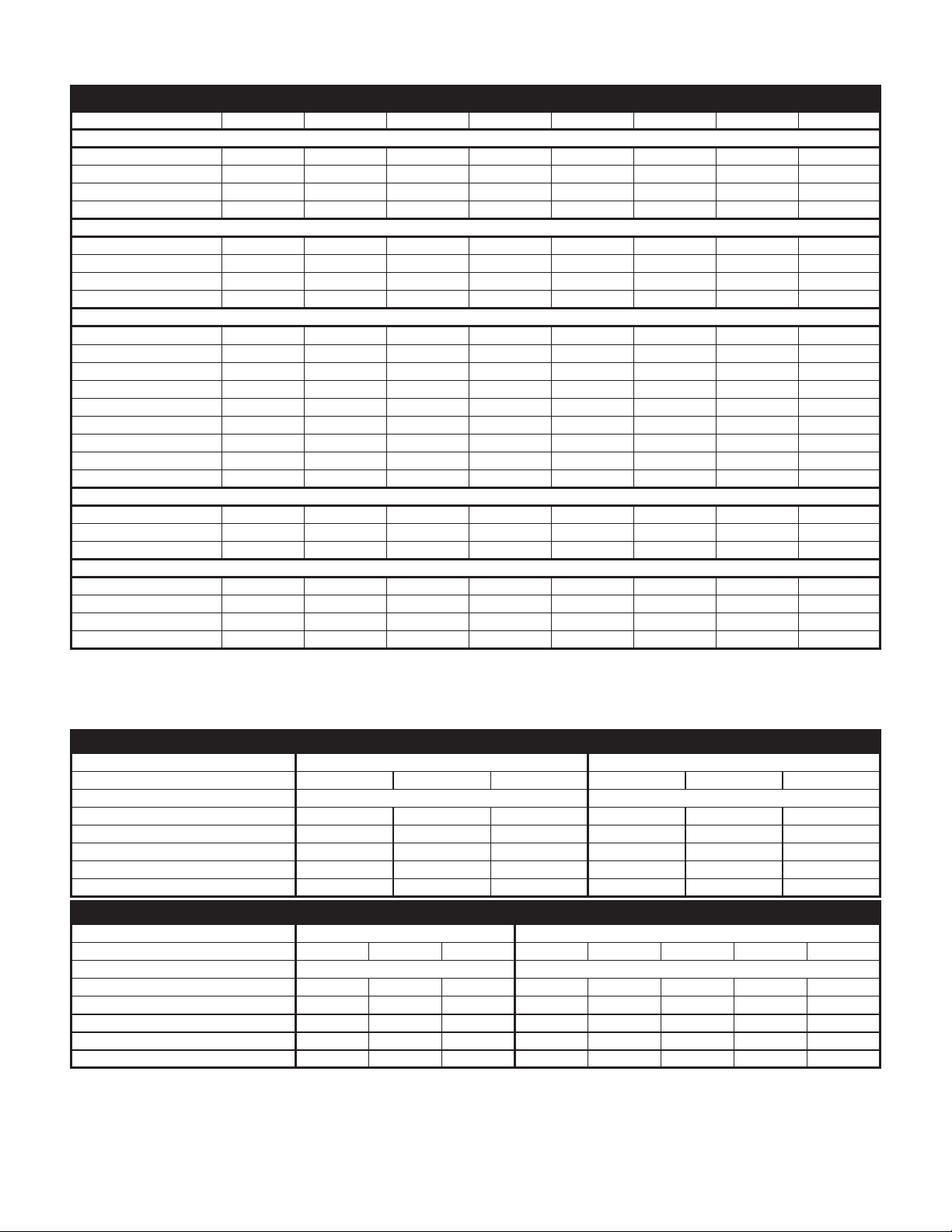
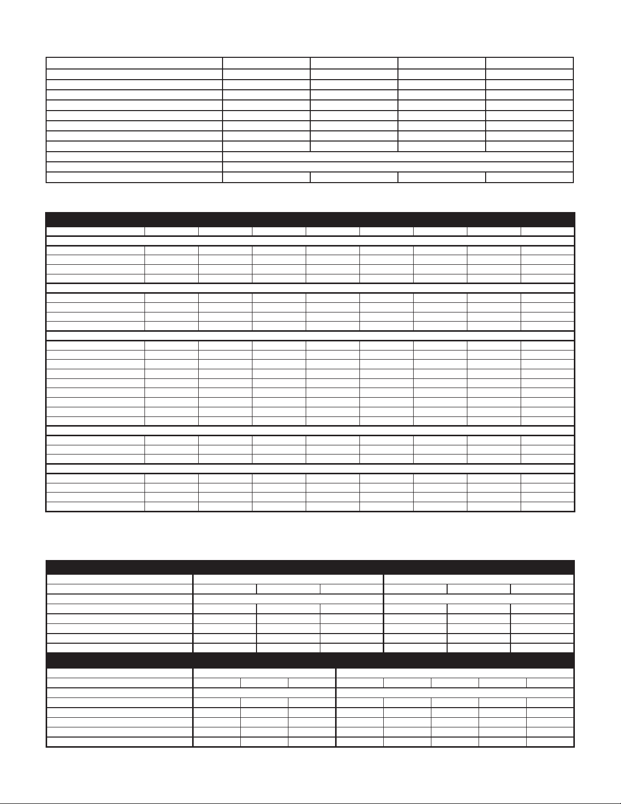
VERT-I-PAK® H SUFFIX CHASSIS SPECIFICATIONS
VEA/VHA9K-24K
VEA09K VEA12K VEA18K VEA24K VHA09K VHA12K VHA18K VHA24K
COOLING DATA
Cooling Btu/h 9500/9300 11800/11500 18000/17800 24000 9500/9300 11800/11500 18000/17800 23500
Cooling Power (W) 880 1093 2070 2526 905 1124 2070 2474
EER 10.8 10.8 8.7 9.5 10.5 10.5 8.7 9.5
Sensible Heat Ratio 0.74 0.72 0.70 0.70 0.74 0.72 0.70 0.70
HEAT PUMP DATA
Heating Btu/h N/A N/A N/A N/A 8500/8300 10600/10400 15700/15500 22500
COP @ 47°F N/A N/A N/A N/A 3.0 3.2 3.0 3
Heating Power (W) N/A N/A N/A N/A 830 971 1705 2200
Heating Current (A) N/A N/A N/A N/A 4.4/4.9 5.5/6.1 9.2/10.2 11.4
ELECTRICAL DATA
Voltage (1 Phase, 60 Hz) 230/208 230/208 230/208 230/208 230/208 230/208 230/208 230/208
Volt Range 253-198 253-198 253-198 253-198 253-198 253-198 253-198 253-198
Cooling Current (A) 4.1/4.3 4.9/5.3 9.2/10.2 11.2/12.4 4.2/4.4 5.0/5.5 9.2/10.2 11.2/12.4
Amps L.R. 21 21 47 68 21 21 47 68
Amps F.L. 3.7 4.5 7.9 10.2 3.7 4.5 7.9 10.2
Indoor Motor (HP) 1/4 1/4 1/4 1/4 1/4 1/4 1/4 1/4
Indoor Motor (A) 1.2 1.2 1.4 2 1.2 1.2 1.4 2
Outdoor Motor (HP) N/A N/A N/A 1/4 N/A N/A N/A 1/4
Outdoor Motor (A) N/A N/A N/A 2 N/A N/A N/A 2
AIRFLOW DATA
Indoor CFM* 300 350 550 750 300 375 550 750
Vent CFM 60 60 60 80 60 60 60 80
Max. ESP .3" .3" .3" .3" .3" .3" .3" .3"
PHYSICAL DATA
Dimensions (W x D x H) 23 x 23 x 32 23 x 23 x 32 23 x 23 x 32 23 x 23 x 47 23 x 23 x 32 23 x 23 x 32 23 x 23 x 32 23 x 23 x 47
Net Weight (Lbs) 114 124 144 167 114 125 144 167
Shipping Weight (Lbs) 125 135 155 180 125 135 155 180
R-22 Charge 25 29 42 68.5 23.5 27 42 63.5
* Normal Value Wet Coil @ .1" ESP.
ELECTRIC HEAT DATA
VEA/VHA09,12
Heater Watts 2500/2050 3400/2780 5000/4090 2500/2050 3400/2780 5000/4090
Heating Btu/h 8500/7000 11600/9500 17000/13900 8500/7000 11600/9500 17000/13900
Heating Current (Amps) 10.6/9.3 14.5/12.5 20.9/18.2 10.6/9.3 14.5/12.5 20.9/18.2
Minimum Circuit Ampacity 15 19.9 27.9 15 19.9 27.9
Branch Circuit Fuse (Amps) 15 20 30 15 20 30
Basic Heater Size 2.5 Kw 3.4 Kw 5.0 Kw 2.5 Kw 3.4 Kw 5.0 Kw
VEA/VHA18,24
Heater Watts 2500/2050 3400/2780 5000/4090 2500/2050 3400/2780 5000/4090 7500/6135 10000/8180
Heating Btu/h 8500/7000 11600/9500 17000/13900 8500/7000 11600/9500 17000/13900 25598/20939 34130/27918
Heating Current (Amps) 10.6/9.3 14.5/12.5 20.9/18.2 10.9/9.9 14.8/13.4 21.7/19.7 32.6/29.5 43.5/39.3
Minimum Circuit Ampacity 15 19.9 27.9 17.2/15.9 22.1/20.3 30.7/28.1 44.3/40.4 57.9/52.7
Branch Circuit Fuse (Amps) 15 20 30 25/25 25/25 35/30 45/45 60/60
Basic Heater Size 2.5 Kw 3.4 Kw 5.0 Kw 2.5 Kw 3.4 Kw 5.0 Kw 7.5 Kw 10.0 Kw
VE/VHA09 VE/VHA12
Voltage 230/208 230/208
VE/VHA18 VE/VHA24
Voltage 230/208 230/208
5
VERT-I-PAK
Model V(E,H)A09 V(E,H)A12 V(E,H)A18 V(E,H)A24
Voltage (V)
Refrigerant
Chassis Width
Chassis Depth
Chassis Height **
Shipping W x D x H
Supply Duct Collar ***
Drain Connection
Min. Circuit Amps
CFM Indoor
Max. Duct ESP
** Height includes 2" duct collar & isolators under unit. *** Factory collar accepts 10" fl ex duct.
®
E & G SUFFIX CHASSIS SPECIFICATIONS
230 / 208 230 / 208 230 / 208 230 / 208
R-22 R-22 R-22 R-22
23.125" 23.125" 23.125" 23.125"
23.125" 23.125" 23.125" 23.125"
32.25" 32.25" 32.25" 47.25"
26" x 28.5" x 35.0" 26." x 28.5" x 35" 26" x 28.5" x 35" 26" x 28.5" x 50"
10" 10" 10" 10"
3/4" FPT 3/4" FPT 3/4" FPT 3/4" FPT
.3 in. water .3 in. water .3 in. water .3 in. water
See Chassis Nameplate
Page 11
VEA/VHA9K-24K
COOLING DATA
Cooling Btu/h 9500/9300 11800/11500 18000/17800 24000 9500/9300 11800/11500 18000/17800 23500
Cooling Power (W) 880 1093 2070 2526 905 1124 2070 2474
EER 10.8 10.8 8.7 9.5 10.5 10.5 8.7 9.5
Sensible Heat Ratio 0.74 0.72 0.70 0.70 0.74 0.72 0.70 0.70
HEAT PUMP DATA
Heating Btu/h N/A N/A N/A N/A 8500/8300 10600/10400 15700/15500 22500
COP @ 47°F N/A N/A N/A N/A 3.0 3.2 3.0 3
Heating Power (W) N/A N/A N/A N/A 830 971 1705 2200
Heating Current (A) N/A N/A N/A N/A 4.4/4.9 5.5/6.1 9.2/10.2 11.4
ELECTRICAL DATA
Voltage (1 Phase, 60 Hz) 230/208 230/208 230/208 230/208 230/208 230/208 230/208 230/208
Volt Range 253-198 253-198 253-198 253-198 253-198 253-198 253-198 253-198
Cooling Current (A) 4.1/4.3 4.9/5.3 9.2/10.2 11.2/12.4 4.2/4.4 5.0/5.5 9.2/10.2 11.2/12.4
Amps L.R. 21 21 47 68 21 21 47 68
Amps F.L. 3.7 4.5 7.9 10.2 3.7 4.5 7.9 10.2
Indoor Motor (HP) 1/4 1/4 1/4 1/4 1/4 1/4 1/4 1/4
Indoor Motor (A) 1.2 1.2 1.4 2 1.2 1.2 1.4 2
Outdoor Motor (HP) N/A N/A N/A 1/4 N/A N/A N/A 1/4
Outdoor Motor (A) N/A N/A N/A 2 N/A N/A N/A 2
AIRFLOW DATA
Indoor CFM* 300 350 550 750 300 375 550 750
Vent CFM 60 60 60 80 60 60 60 80
Max. ESP .3" .3" .3" .3" .3" .3" .3" .3"
PHYSICAL DATA
Dimensions (W x D x H) 23x23x32 23x23x32 23x23x32 23x23x47 23x23x32 23x23x32 23x23x32 23x23x47
Net Weight (Lbs) 114 124 144 167 114 125 144 167
Shipping Weight (Lbs) 125 135 155 180 125 135 155 180
R-22 Charge 25 29 42 68.5 23.5 27 42 63.5
* Normal Value Wet Coil @ .1" ESP.
VEA09K VEA12K VEA18K VEA24K VHA09K VHA12K VHA18K VHA24K
ELECTRIC HEAT DATA
VEA/VHA09,12
Heater Watts 2500/2050 3400/2780 5000/4090 2500/2050 3400/2780 5000/4090
Heating Btu/h 8500/7000 11600/9500 17000/13900 8500/7000 11600/9500 17000/13900
Heating Current (Amps) 10.6/9.3 14.5/12.5 20.9/18.2 10.6/9.3 14.5/12.5 20.9/18.2
Minimum Circuit Ampacity 15 19.9 27.9 15 19.9 27.9
Branch Circuit Fuse (Amps) 15 20 30 15 20 30
Basic Heater Size 2.5 Kw 3.4 Kw 5.0 Kw 2.5 Kw 3.4 Kw 5.0 Kw
VEA/VHA18,24
Heater Watts 2500/2050 3400/2780 5000/4090 2500/2050 3400/2780 5000/4090 7500/6135 10000/8180
Heating Btu/h 8500/7000 11600/9500 17000/13900 8500/7000 11600/9500 17000/13900 25598/20939 34130/27918
Heating Current (Amps) 10.6/9.3 14.5/12.5 20.9/18.2 10.9/9.9 14.8/13.4 21.7/19.7 32.6/29.5 43.5/39.3
Minimum Circuit Ampacity 15 19.9 27.9 17.2/15.9 22.1/20.3 30.7/28.1 44.3/40.4 57.9/52.7
Branch Circuit Fuse (Amps) 15 20 30 25/25 25/25 35/30 45/45 60/60
Basic Heater Size 2.5 Kw 3.4 Kw 5.0 Kw 2.5 Kw 3.4 Kw 5.0 Kw 7.5 Kw 10.0 Kw
6
VE/VHA09 VE/VHA12
Voltage 230/208 230/208
VE/VHA18 VE/VHA24
Voltage 230/208 230/208
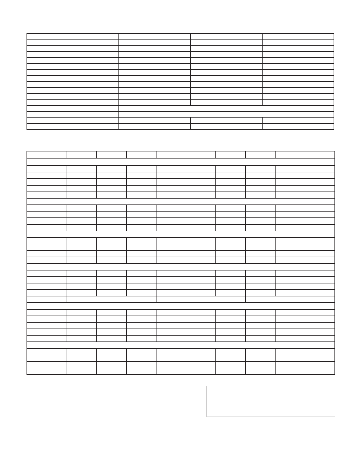
VERT-I-PAK® A - D SUFFIX CHASSIS SPECIFICATIONS
Model V(E,H)A09 V(E,H)A12 V(E,H)A18
Voltage (V) 230 / 208 230 / 208 230 / 208
Refrigerant R-22 R-22 R-22
Chassis Width 23.125" 23.125" 23.125"
Chassis Depth 23.125" 23.125" 23.125"
Chassis Height ** 32.25" 32.25" 32.25"
Shipping W x D x H 26" x 28" x 35" 26" x 28" x 35" 26" x 28" x 35"
Supply Duct Collar *** 10" 10" 10"
Drain Connection 1/2" MPT 1/2" MPT 1/2" MPT
Drain Hose **** 12" long 12" long 12" long
Thermostat Harness 36" long 36" long 36" long
Power Cord 60" long 60" long 60" long
Min. Circuit Amps See Chassis Nameplate
CFM Indoor Page 15
Fan Speeds 222
Max. Duct ESP .3 In. water .3 In. water .3 In. water
NOTES: ** Height includes 2" duct collar & isolators under unit. *** Factory collar accepts 10" fl ex duct.
MODELS V(E,H)A09K25 V(E,H)A09K34 V(E,H)A09K50 V(E,H)A12K25 V(E,H)A12K34 V(E,H)A12K50 V(E,H)A18K25 V(E,H)A18K34 V(E,H)A18K50
Cooling Cap. (Btu/h) 9500/9300 9500/9300 9500/9300 11500/11300 11500/11300 11500/11300 17200/17000 17200/17000 17200/17000
Cooling Power (W) 950 950 950 1200 1200 1200 1911 1911 1911
SEER 10.0 10.0 10.0 10.0 10.0 10.0 10.0 10.0 10.0
Water Removal (Pts/h) 2.1 2.1 2.1 2.8 2.8 2.8 4.0 4.0 4.0
Cooling SHR 0.77 0.77 0.77 0.76 0.76 0.76 0.75 0.75 0.75
Heater Size (KW) 2.5 3.4 5.0 2.5 3.4 5.0 2.5 3.4 5.0
Heating Cap.(Btu/h) 8500/7000 11600/9500 17000/13900 8500/7000 11600/9500 17000/13900 8500/7000 11600/9500 17000/13900
Heating Power (W) 2500/2050 3500/2780 5000/4090 2500/2050 3500/2780 5000/4520 2500/2050 3500/2780 5000/4520
Heating Current (A) 11.9/11.2 15.9/14.6 22.6/20.6 11.9/11.2 15.9/14.6 22.6/20.6 11.9/11.2 15.9/14.6 22.6/20.6
Heating Cap.(Btu/h) 8000/7800 8000/7800 8000/7800 11200/11000 11200/11000 11200/11000 15700/15500 15700/15500 15700/15500
Heating Power (W) 950 950 950 1200 1200 1200 1830 1830 1830
Heating Current (A) 4.4/4.9 4.4/4.9 4.4/4.9 5.2/6.0 5.2/6.0 5.2/6.0 9.0/10.0 9.0/10.0 9.0/10.0
0
COP @ 47
Voltage (V) 230/208 230/208 230/208 230/208 230/208 230/208 230/208 230/208 230/208
LRA - Comp. (A) 2 0 20 20 26.3 26.0 26.3 45 45 45
Cooling Current (A) 4.4/4.9 4.4/4.9 4.4/4.9 5.5/6.1 5.2/6.0 5.2/6.0 7.6 7.6 7.6
MIN. Ckt. Amps (A) 15 20 30 15 20 30 15 20 30
Power Connection POWER CORD POWER CORD POWER CORD WITH OPTION TO HARD WIRE
Refrigerant R-22 R-22 R-22 R-22 R-22 R-22 R-22 R-22 R-22
Unit Width (in.) 23.125 23.125 23.125 23.125 23.125 23.125 23.125 23.125 23.125
Unit Depth (in.) 23.125 23.125 23.125 23.125 23.125 23.125 23.125 23.125 23.125
Unit Height* (in.) 32.25 32.25 32.25 32.25 32.25 32.25 32.25 32.25 32.25
Shipping Weight (lbs.) 125 125 125 135 135 135 155 155 155
Indoor CFM ** 300 300 300 375 375 375 550 550 550
Fresh Air CFM** 60 60 60 60 60 60 60 60 60
Motor 230V, 1/4 HP 230V, 1/4 HP 230V, 1/4 HP 230V, 1/4 HP 230V, 1/4 HP 230V, 1/4 HP 230V, 1/4 HP 230V, 1/4 HP 230V, 1/4 HP
Motor Amps** 1.4 1.4 1.4 1.4 1.4 1.4 1.4 1.4 1.4
F 3.0 3.0 3.0 3.0 3.0 3.0 2.4 2.4 2.4
*Height includes 2" high duct collar and 5/8" isolators under unit.
**Normal Value Dry Coil on High Speed @ .3" ESP.
Due to continuing research in new energy-saving technology,
specifi cations are subject to change without notice.
Capacity rated at standard conditions:
COOLING–
950F DB/750F WB outdoor, 800F DB/670F WB indoor
HEATING– (reverse cycle)
0
F DB/430F WB outdoor, 700F DB/600F WB indoor
47
7
Sequence of Operation
A good understanding of the basic operation of the refrigeration
system is essential for the service technician. Without this
understanding, accurate troubleshooting of refrigeration
system problems will be more diffi cult and time consuming,
if not (in some cases) entirely impossible. The refrigeration
system uses four basic principles (laws) in its operation they
are as follows:
1. "Heat always fl ows from a warmer body to a cooler
body."
2. "Heat must be added to or removed from a substance
before a change in state can occur"
3. "Flow is always from a higher pressure area to a lower
pressure area."
4. "The temperature at which a liquid or gas changes state
is dependent upon the pressure."
The refrigeration cycle begins at the compressor. Starting
the compressor creates a low pressure in the suction line
which draws refrigerant gas (vapor) into the compressor.
The compressor then "compresses" this refrigerant, raising
its pressure and its (heat intensity) temperature.
The refrigerant leaves the compressor through the discharge
line as a HOT high pressure gas (vapor). The refrigerant
enters the condenser coil where it gives up some of its
heat. The condenser fan moving air across the coil's fi nned
surface facilitates the transfer of heat from the refrigerant to
the relatively cooler outdoor air.
When a suffi cient quantity of heat has been removed from the
refrigerant gas (vapor), the refrigerant will "condense" (i.e.)
change to a liquid). Once the refrigerant has been condensed
(changed) to a liquid it is cooled even further by the air that
continues to fl ow across the condenser coil.
The Vert-I-Pak design determines at exactly what point
(in the condenser) the change of state (i.e. gas to a liquid)
takes place. In all cases, however, the refrigerant must be
totally condensed (changed) to a liquid before leaving the
condenser coil.
The refrigerant leaves the condenser coil through the liquid
li ne as a WAR M high press ure liquid. It nex t wil l pass throu gh
the refrigerant drier (if so equipped). It is the function of the
drier to trap any moisture present in the system, contaminants,
and LARGE particulate matter.
The liquid refrigerant next enters the metering device. The
metering device is a capillary tube. The purpose of the
metering device is to "meter" (i.e. control or measure) the
quantity of refrigerant entering the evaporator coil.
In the case of the capillary tube this is accomplished (by
design) through size (and length) of device, and the pressure
difference present across the device.
Since the evaporator coil is under a lower pressure (due to
the suction created by the compressor) than the liquid line,
the liquid refrigerant leaves the metering device entering the
evaporator coil. As it enters the evaporator coil, the larger
area and lower pressure allows the refrigerant to expand
and lower its temperature (heat intensity). This expansion is
often referred to as "boiling". Since the unit's blower is moving
Indoor air across the fi nned surface of the evaporator coil,
the expanding refrigerant absorbs some of that heat. This
results in a lowering of the indoor air temperature, hence the
"cooling" effect.
The expansion and absorbing of heat cause the liquid
refrigerant to evaporate (i.e. change to a gas). Once the
refrigerant has been evaporated (changed to a gas), it is
heated even further by the air that continues to fl ow across
the evaporator coil.
The particular system design determines at exactly what
point (in the evaporator) the change of state (i.e. liquid to a
gas) takes place. In all cases, however, the refrigerant must
be totally evaporated (changed) to a gas before leaving the
evaporator coil.
The low pressure (suction) created by the compressor causes
the the refrigerant to leave the evaporator through the suction
line as a COOL low pressure vapor. The refrigerant then
returns to the compressor, where the cycle is repeated.
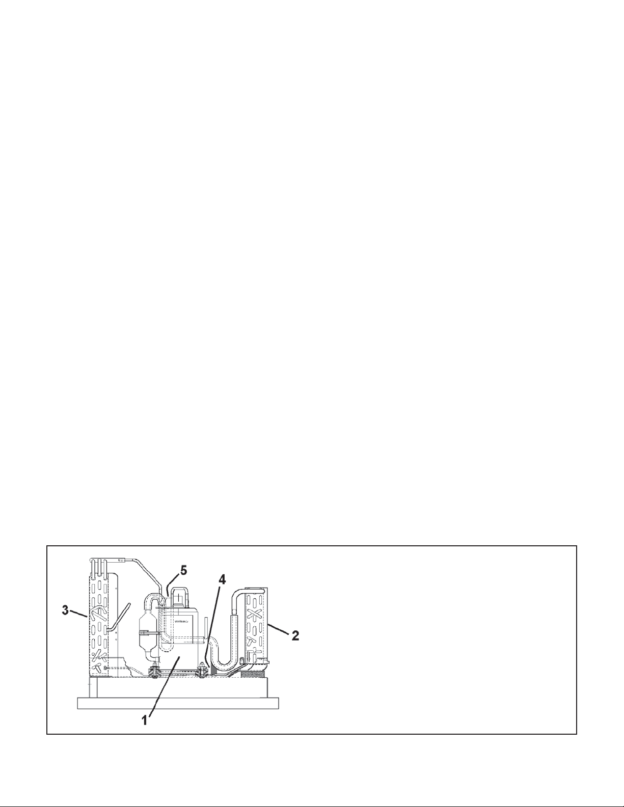
Refrigeration Assembly
1. Compressor
2. Evaporator Coil Assembly
3. Condenser Coil Assembly
4. Capillary Tube
5. Compressor Overload
8
Electrical Supply
WARNING: Electrical shock hazard.
Turn OFF electric power at fuse box or service panel
before making any electrical connections and ensure a
proper ground connection is made before connecting line
voltage.
All electrical connections and wiring MUST be installed by
a qualifi ed electrician and conform to the National Electrical
Code and all local codes which have jurisdiction.
Failure to do so can result in property damage, personal
injury and/or death.
Supply Circuit
The system cannot be expected to operate correctly unless
the system is properly connected (wired) to an adequately
sized single branch circuit. Check the installation manual
and/or technical data for your particular unit and/or strip
heaters to determine if the circuit is adequately sized.
Electrical Rating Tables
NOTE: Use copper conductors ONLY
Wire sizes are per NEC. Check local codes for
overseas applications
Supply Voltage
To insure proper operation, supply voltage to the system
should be within fi ve (5) percent (plus or minus) of listed
rating plate voltage.
Control (Low) Voltage
To insure proper system operation, the transformer
secondary output must be maintained at a nominal 24 volts.
The control (low) voltage transformer is equipped with
multiple primary voltage taps. Connecting the primary,
(supply) wire to the tap (i.e., 208 and 240 volts) that most
closely matches the MEASURED supply voltage will insure
proper transformer secondary output is maintained.
Supply Voltage
Supply voltage to the unit should be a nominal 208/230 volts.
It must be between 197 volts and 253 volts. Supply voltage
to the unit should be checked WITH THE UNIT IN
OPERATION. Voltage readings outside the specifi ed range
can be expected to cause operating problems. Their cause
MUST be investigated and corrected.
Electrical Ground
GROUNDING OF THE ELECTRICAL SUPPLY TO ALL
UNITS IS REQUIRED for safety reasons.
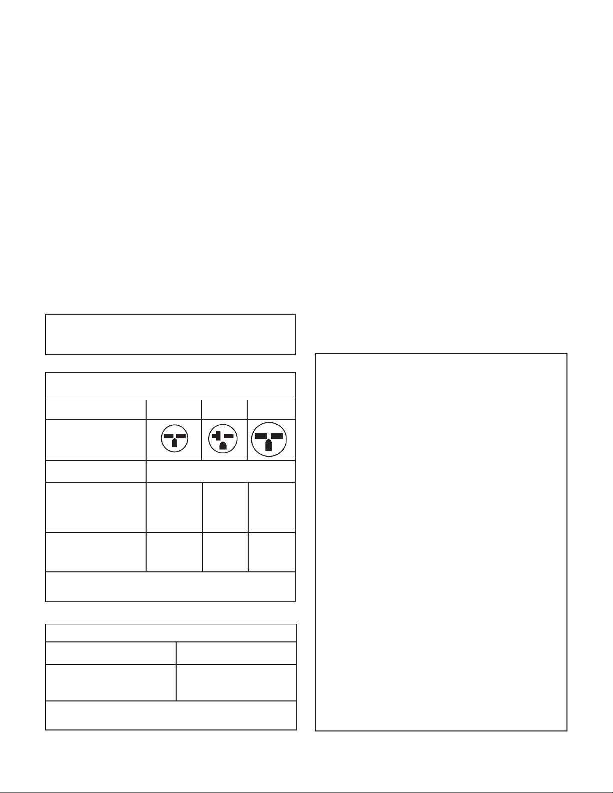
A through D Suffi x
250 V Receptacles and Fuse Types
Units Only
AMPS 15 20 * 30
RECEPTACLE
MANUFACTURER PART NUMBERS
Hubbell 5661 5461 9330
P & S 5661 5871 5930
GE GE4069-1 GE4182-1 GE4139-3
Arrow-Hart 5661 5861 5700
TIME-DELAY TYPE
FUSE 15 20 30
(or HACR circuit breaker)
HACR — Heating, Air Conditioning, Refrigeration
* May be used for 15 Amp applications if fused for 15 Amp
Recommended branch circuit wire sizes*
Nameplate maximum circuit
breaker size
15A 14
20A 12
30A 10
AWG — American Wire Gauge
* Single circuit from main box
** Based on copper wire, single insulated conductor at 60°C
AWG Wire size**
Electrical Requirements
NOTE: All fi eld wiring must comply with
NEC and local codes. It is the
responsibility of the installer to
insure that the electrical codes are
met.
Wire Size Use ONLY w iring size r ecomme nded
for single outlet branch circuit.
Fuse/Circuit Use ONLY type and size fuse or
HACR circuit breaker
Breaker Indicated on unit's rating plate (See
sample on page 6).
Proper current protection to the unit
is the responsibility of the owner.
Grounding Unit MUST be grounded from branch
circuit to unit, or through separate
ground wire provided on permanently
connected units. Be sure that branch
circuit or general purpose outlet is
grounded.
Wire Sizing Use recommended wire size given in
the tables below and install a single
branch circuit. All wiring must comply
with local and national codes. NOTE:
Use copper conductors only.
9
Room Thermostats
Room thermostats are available from several different
manufacturers in a wide variety of styles. They range from
the very simple Bimetallic type to the complex electronic
set-back type. In all cases, no matter how simple or
complex, they are simply a switch (or series of switches)
designed to turn equipment (or components) "ON" or "OFF"
at the desired conditions.
An improperly operating, or poorly located room thermostat
can be the source of perceived equipment problems. A
careful check of the thermostat and wiring must be made
then to insure that it is not the source of problems.
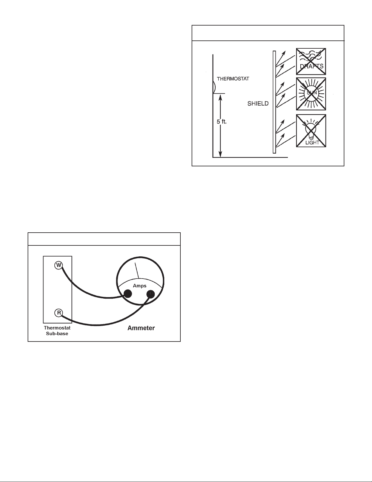
Location
The thermostat should not be mounted where it may be
affected by drafts, discharge air from registers (hot or cold),
or heat radiated from the sun or appliances.
The thermostat should be located about 5 Ft. above the
fl oor in an area of average temperature, with good air
circulation. Close proximity to the return air grille is the
best choice.
Mercury bulb type thermostats MUST be level to control
temperature accurately to the desired set-point. Electronic
digital type thermostats SHOULD be level for aesthetics.
Measuring Current Draw
Thermostat Location
In order to accomplish this, the heat output from the
anticipator must be the same regardless of the current
fl owing through it. Consequently, some thermostats have
an adjustment to compensate for varying current draw in
the thermostat circuits.
The proper setting of heat anticipators then is important
to insure proper temperature control and customer
satisfaction. A Heat anticipator that is set too low will
cause the heat source to cycle prematurely possibly never
reaching set point. A heat anticipator that is set too high
will cause the heat source to cycle too late over shooting
the set point.
Heat Anticipators
Heat anticipators are small resistance heaters (wired
in series with the "W" circuit) and built into most
electromechanical thermostats. Their purpose is to prevent
wide swings in room temperature during system operation
in the HEATING mode. Since they are wired in series,
the "W" circuit will open if one burns out preventing heat
operation.
The heat anticipator provides a small amount of heat to
the thermostat causing it to cycle (turn off) the heat source
just prior to reaching the set point of the thermostat. This
prevents exceeding the set point.
10
The best method to obtain the required setting for the
heat anticipator, is to measure the actual current draw in
the control circuit ("W") using a low range (0-2.0 Amps)
Ammeter. After measuring the current draw, simply set
the heat anticipator to match that value.
If a low range ammeter is not available, a "Clamp-on" type
ammeter may be used as follows:
1. Wrap EXACTLY ten (10) turns of wire around the jaws
of a clamp-on type ammeter.
2. Connect one end of the wire to the "W" terminal of
the thermostat sub-base, and the other to the "R"
terminal.
3. Turn power on, and wait approximately 1 minute, then
read meter.
4. Divide meter reading by 10 to obtain correct anticipator
setting.
Electronic thermostats do not use a resistance type
anticipator. These thermostats use a microprocessor
(computer) that determines a cycle rate based on a
program loaded into it at the factory.
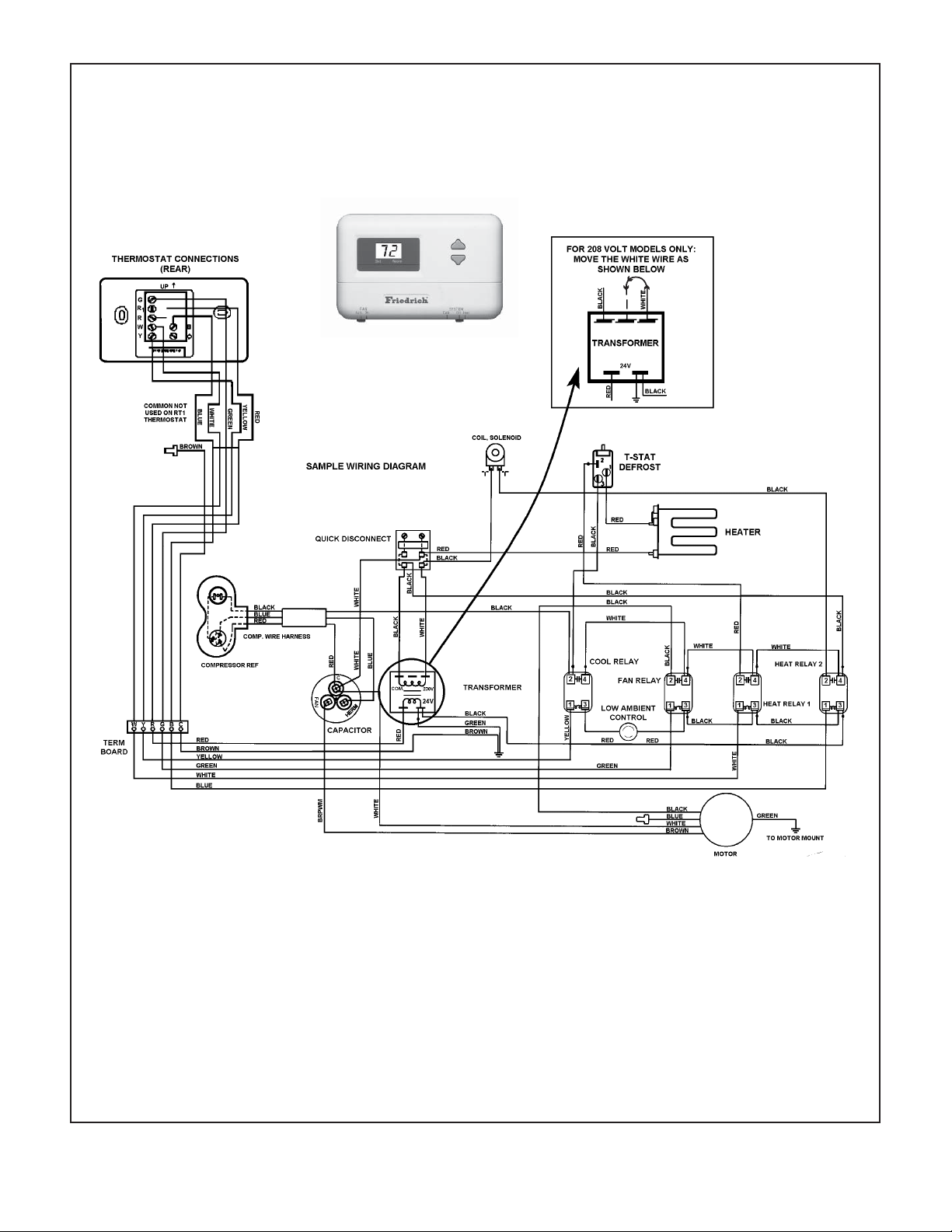
Typical Electrical & Thermostat Wiring Diagrams
VEA/VHA 24K
FOR 208 VOLT MODELS ONLY
MOVE THE WHITE WIRE AS
RT2
THERMOSTAT
(FRONT)
SHOWN BELOW
BLACK
COM.
208V 240V
WHITE
THERMOSTAT CONNECTIONS
(EAR)
UP
G
R
R
W
Y
WHITE
BROWN
TERM BOARD
BROWN
YELLOW
YWRGBC
TRANSFORMER
24V
BLACK
B
C
RED
RED
c
CAPACITOR
HERM
WHITE
QUICK DISCONNECT
L1
BLACK
BLUE
COM.
TRANSFORMER
24V
208V
L2
WHITE
240V
GREEN
SEE NOTE #6
TO MOTOR
MOUNT
WHITE
RED
BLACK
RED
BLACK
BLACK
GREEN
CONDENSER
MOTOR
RED
BLACK
BLUE
RED
"F"
S
COMP WIRE HARNESS
R
C
"F"
"F"
COMPRESSOR
FAN
BLACK
BLUE
GREEN
RED
YELLOW
WHITE
123
COMPR RELAY
4
LOW AMBIENT
RED
BLACK
WHITE
BROWN
RED
COIL, SOLENOID
RED
BLACK
WHITE
CONTROL
WIRE NUT (RED)
WHITE
RED
PRESSURE
SWITCH
YELLOW
CAPACITOR
YELLOW
HEATER
2.5 KW & 3.4 KW
5 KW
WHITE
FAN
RELAY
2
2 4
1 3
BLACK
BLACK
c
FAN
BROWN
HERM
RED
REV VALVE
4
31
RELAY
WHITE
BLUE
HEAT
RELAY
(2.5KW/3.4KW
2 4
1 3 123
BLACK
BLACK
RED
C
H
L
GREEN
BLOWER
MOTOR
5 KW)
T-STAT
DEFROST
INSULATOR
2-REQ'D
WIRE NUT (RED)
SEE NOTE #4
BLACK
TO MOTOR
MOUNT
7.5 KW & 10 KW
RED
RELAY
2 4
1 3
HEATER
HEAT
(2.5KW/3.4KW
5 KW)
BLACK
BLACK
RED
RED
HEAT
RELAY
(7.5KW/10KW) (7.5KW/10KW)
2
4
1
BLACK
BLACK
HEAT
RELAY
4
3
NOTE: THE DIAGRAM ABOVE ILLUSTRATES THE TYPICAL THERMOSTAT WIRING AND 208
VOLT TRANSFORMER WIRING. SEE THE UNIT CONTROL PANEL FOR THE ACTUAL
UNIT WIRING DIAGRAM AND SCHEMATIC.
11
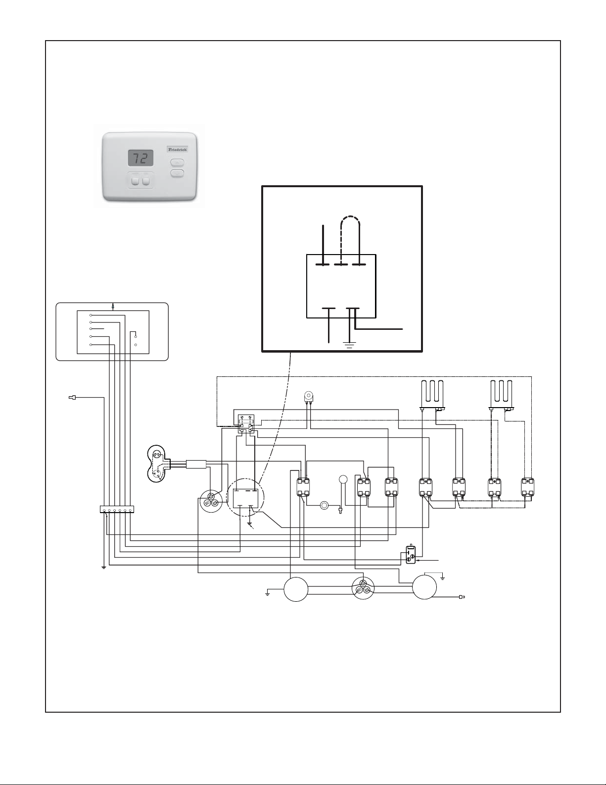
Typical Electrical & Thermostat Wiring Diagrams
G & H Suffi x
COM. 208V 240V
RT1
THERMOSTAT
(FRONT)
12
NOTE: THE DIAGRAM ABOVE ILLUSTRATES THE TYPICAL
THERMOSTAT WIRING AND 208 VOLT TRANSFORMER
WIRING. SEE THE UNIT CONTROL PANEL FOR THE
ACTUAL UNIT WIRING DIAGRAM AND SCHEMATIC.
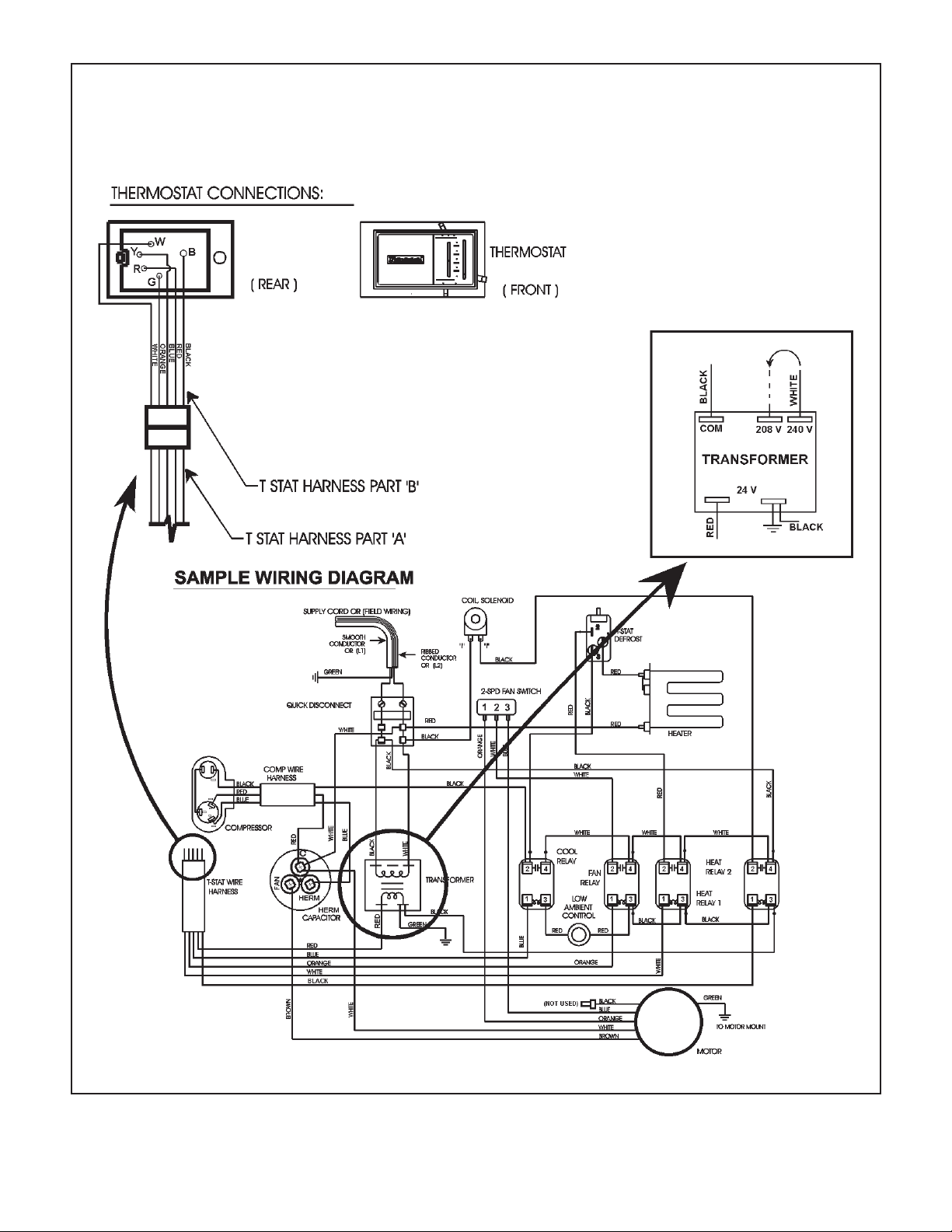
Typical Electrical & Thermostat Wiring Diagrams
A – E Suffi x
FOR 208 VOLT MODELS ONLY:
MOVE THE WHITE WIRE AS
SHOWN BELOW.
13

Indoor Blower - Airfl ow
The current Vert-I -Pak 9, 12, & 18 use a dual shaft, permanent
split capacitor, single speed motor to drive indoor blower and
outdoor fan. Earlier model VERT-I-Pak units used 2-speed
motors. The Vert-I-Pak 24 uses an individual, single shaft,
permanent split capacitor, single speed motor for the indoor
blower, and a separate motor drives the outdoor fan.
Different size (HP) motors and/or different diameter blower
wheels are used in different models to obtain the required
airfl ow.
Condenser Fan Motors
The current Vert-I-Pak 9, 12, & 18 units use a dual shaft,
permanent split capacitor, single speed motor to drive indoor
and outdoor fan. Earlier models used a 2-speed motor. The
Vert-I-Pak 24 uses and individual, single shaft, permanent
split capacitor, single speed motor for the outdoor fan, with a
separate motor driving the indoor blower.
Blower Wheel Inspection
Visually inspect the blower wheel for the accumulations
of dirt or lint since they can cause reduced airfl ow. Clean
the blower wheel of these accumulations. If accumulation
cannot be removed, it will be necessary to remove the
blower assembly from the unit for proper wheel cleaning.
Cooling
A nominal 400 (350-450 allowable) CFM per ton of airfl ow
is required to insure proper system operation, capacity,
and effi ciency. Factory-set blower speeds should provide
the proper airfl ow for the size (Cooling capacity) of the unit
when connected to a properly sized duct system.
Cooling (VEA/VHA 24)
When the thermostat is set for cooling mode (SYSTEM
switch set to COOL and FAN switch to AUTO) a rise in room
temperature will make It also causes a 24-volt signal on the
“Y” thermostat conductor through the high pressure and low
ambient switches energizing the compressor relay, turning
on the compressor and outdoor fan motor. A 24-volt signal
on the “G” thermostat terminal to the Fan Relay, turning on
the indoor blower motor.
Heating (Electric)
When using electric heaters, select the blower speed that
provides adequate airfl ow across the elements to prevent
overheating and cycling on limit and/or premature failure.
CHECK THE EXTERNAL STATIC PRESSURE, and then
consult the AIR FLOW DATA to determine the ACTUAL air
fl ow delivered for the factory selected fan speed. This will
be especially important on change-outs using an existing
duct system that may not have been properly sized to
begin with.
Heating (VEA/VHA 24)
When the thermostat is set for heating mode (System switch
set to HEAT and FAN switch to AUTO) it will make a 24volt signal on the “B” thermostat terminal to energize the
Reversing Valve Relay. A drop in room temperature, will
make a 24-volt signal on the “W” thermostat terminal to the
Defrost Thermostat, and “G” thermostat terminal to the Fan
Relay. The Defrost Thermostat will determine whether the
unit should run in Heat Pump, or Electric Heat, based on the
outdoor temperature. (See Defrost Thermostat page 24)
External Static Pressure
External Static Pressure can best be defi ned as the pressure
difference (drop) between the Positive Pressure (discharge)
and the Negative Pressure (intake) sides of the blower.
External Static Pressure is developed by the blower as a
result of resistance to airfl ow (Friction) in the air distribution
system EXTERNAL to the VERT-I-PAK cabinet.
Resistance applied externally to the VERT-I-PAK (i.e. duct
work, coils, fi lters, etc.) on either the supply or return side
of the system causes an INCREASE in External Static
Pressure accompanied by a REDUCTION in airfl ow.
External Static Pressure is affected by two (2) factors.
1. Resistance to Airfl ow as already explained.
2. Blower Speed. Changing to a higher or lower blower
speed will raise or lower the External Static Pressure
accordingly.
These affects must be understood and taken into consideration
when checking External Static Pressure/Airfl ow to insure that
the system is operating within design conditions.
Operating a system with insuffi cient or excessive airfl ow
can cause a variety of different operating problems.
Among these are reduced capacity, freezing evaporator
coils, premature compressor and/or heating component
failures. etc.
System air fl o w s hould always be veri fi e d upon co mp letion
of a new installation, or before a change-out, compressor
replacement, or in the case of heat strip failure to insure
that the failure was not caused by improper airfl ow.
14
 Loading...