


Friedrich SS08, SS10, SS12, SS14, SM15 Installation Guide
...<![endif]>Installation and Operation Manual
Room Air Conditioners
AUTO |
|
AUTO |
°F °C |
CONTINUOUS |
|
AUTO |
|
SYSTEM |
FAN MODE |
SCHEDULE |
FAN SPEED |
Standard Chassis Models
115-Volt: SS08, SS10, SS12, SS14, SM15
208-230-Volt: SS12, SS15, SM18, SM21
SM24, SL28, SL36
115-Volt: YS10
208-230-Volt: ES12, ES15, YS12, EM18
YM18, EM24, EL36, YL24
920-198-12 (3-11)
THANK YOU!
your unit to assure quiet operation, the greatest circulation of cool, dry air, and the most economic operation.
UL |
MODEL NUMBER
AIR CONDITIONING CO. YS10M10A
SAN ANTONIO, TEXAS SERIAL NUMBER
ASSEMBLED IN MEXICO LICY00008
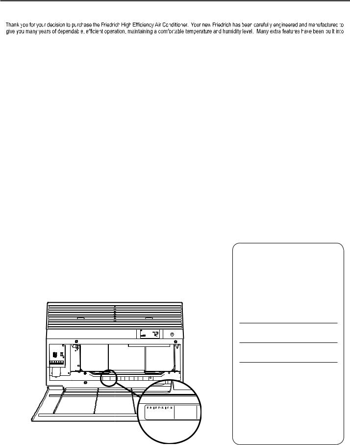
Register your air conditioner
Model information can be found on the name plate behind the front cover.
P l e a s e c o m p l e t e a n d m a i l t h e o w n e r registration card furnished with this product, or register online at www.friedrich.com (USA only). For your future convenience, record the model information here.
MODEL NUMBER
SERIAL NUMBER
PURCHASE DATE
2

|
TABLE OF CONTENTS |
Safety Precautions ................................................................................................................................................................................................................... |
4 |
Unpacking Instructions............................................................................................................................................................................................................. |
5 |
WARNING: Before Operating Your Unit .................................................................................................................................................................................. |
6 |
Standard Filter Cleaning / Installation Instructions .................................................................................................................................................................. |
7 |
Premium Carbon Filter Installation Instructions....................................................................................................................................................................... |
8 |
Control Panel Operation ........................................................................................................................................................................................................ |
10 |
Add a Remote Thermostat ..................................................................................................................................................................................................... |
14 |
Remote Thermostat Selection ............................................................................................................................................................................................... |
14 |
Remote Control Operation ..................................................................................................................................................................................................... |
15 |
Remote Effectiveness ............................................................................................................................................................................................................ |
15 |
.......................................................................................................................................................................................... |
17 |
Installation Instructions .......................................................................................................................................................................................................... |
18 |
Standard Window Installation ................................................................................................................................................................................................ |
20 |
Cord Routing Change ............................................................................................................................................................................................................ |
30 |
Through-the-Wall Installation................................................................................................................................................................................................. |
32 |
Programmable Thermostat .................................................................................................................................................................................................... |
36 |
Final Inspection & Start-up Checklist..................................................................................................................................................................................... |
38 |
Routine Maintenance ............................................................................................................................................................................................................. |
39 |
Service and Assistance ......................................................................................................................................................................................................... |
39 |
Available Accessories ............................................................................................................................................................................................................ |
39 |
Troubleshooting Tips.............................................................................................................................................................................................................. |
40 |
Addendum 1 ........................................................................................................................................................................................................................... |
42 |
3
Safety Precautions
Your safety and the safety of others are very important.
WE HAVE PROVIDED MANY IMPORTANT SAFETY MESSAGES IN THIS MANUAL AND ON YOUR APPLIANCE. ALWAYS READ AND OBEY ALL SAFETY MESSAGES.
THIS IS A SAFETY ALERT SYMBOL.
THIS SYMBOL ALERTS YOU TO POTENTIAL HAZARDS THAT CAN KILL OR HURT YOU AND OTHERS.
ALL SAFETY MESSAGES WILL FOLLOW THE SAFETY ALERT SYMBOL WITH THE WORD “WARNING” OR “CAUTION”. THESE WORDS MEAN:
 WARNING
 CAUTION
INDICATES A HAZARD WHICH, IF NOT AVOIDED, CAN RESULT IN SEVERE PERSONAL INJURY OR DEATH AND DAMAGE TO PRODUCT OR OTHER PROPERTY.
INDICATES A HAZARD WHICH, IF NOT AVOIDED, CAN RESULT IN PERSONAL INJURY AND DAMAGE TO PRODUCT OR OTHER PROPERTY.
ALL SAFETY MESSAGES WILL TELL YOU WHAT THE POTENTIAL HAZARD IS, TELL YOU HOW TO REDUCE THE CHANCE OF INJURY, AND TELL YOU WHAT WILL HAPPEN IF THE INSTRUCTIONS ARE NOT FOLLOWED.
NOTICE
INDICATES PROPERTY DAMAGE CAN OCCUR IF INSTRUCTIONS ARE NOT FOLLOWED.
 WARNING
Refrigeration system under high pressure
DO NOT PUNCTURE, HEAT, EXPOSE TO FLAME OR INCINERATE.
ONLY CERTIFIED REFRIGERATION TECHNICIANS SHOULD SERVICE THIS EQUIPMENT.
R410A SYSTEMS OPERATE AT HIGHER PRESSURES THAN R22 EQUIPMENT. APPROPRIATE SAFE SERVICE AND HANDLING PRACTICES MUST BE USED.
ONLY USE GAUGE SETS DESIGNED FOR USE WITH R410A. DO NOT USE STANDARD R22 GAUGE SETS.
4
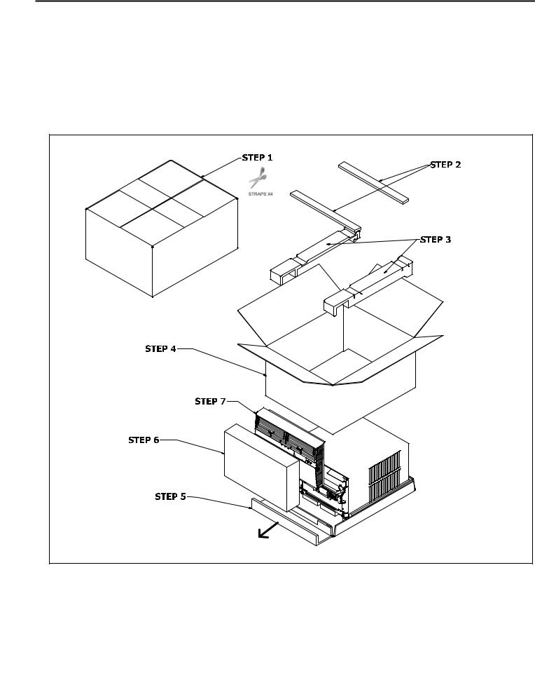
Unpacking Instructions
STEP 1. Cut all 4 packing straps.
STEP 2. Remove wooden shipping bar dividers.
STEP 3. Remove top foam pads.
STEP 5. |
Slide the foam front support forward |
STEP 6. |
Carefully lift decorative front box from foam front support |
STEP 7. |
Remove decorative front and set safely aside |
STEP 4. Slowly remove outer box, careful not to loosen decorative front.
5 |
WARNING: Before Operating Your Unit
 WARNING
Electrical Shock Hazard
Make sure your electrical receptacle has the same configuration as your air conditioner’s plug. If different, consult a Licensed Electrician.
Do not use plug adapters.
Do not use an extension cord. Do not remove ground prong.
Always plug into a grounded 3 prong oulet. Failure to follow these instructions can result in death, fire, or electrical shock.
NOTICE
Do not use the LCDI device as an ON/OFF switch.
Failure to adhere to this precaution may cause premature equipment malfunction.
Once plugged in, the unit will operate normally without the need to reset the LCDI device. If the LCDI device fails to trip when tested or if the power supply cord is damaged, it must be replaced with a new power supply cord from the manufacturer. Contact our Technical Assistance Line at (800) 541-6645. To expedite service, please have your model number available.
Make sure the wiring is adequate for your unit.
If you have fuses, they should be of the time delay type. Before you install or relocate this unit, be sure that the amperage rating of the circuit breaker or time delay fuse does not exceed the amp rating listed in Table 1.
DO NOT use an extension cord.
The cord provided will carry the proper amount of electrical power to the unit; an extension cord may not.
Make sure that the receptacle is compatible with the air conditioner cord plug provided.
Proper grounding must be maintained at all times. Two prong receptacles
The grounded receptacle should meet all national and local codes and ordinances. You must use the three prong plug furnished with the air conditioner. Under no circumstances should you remove the ground prong from the plug.
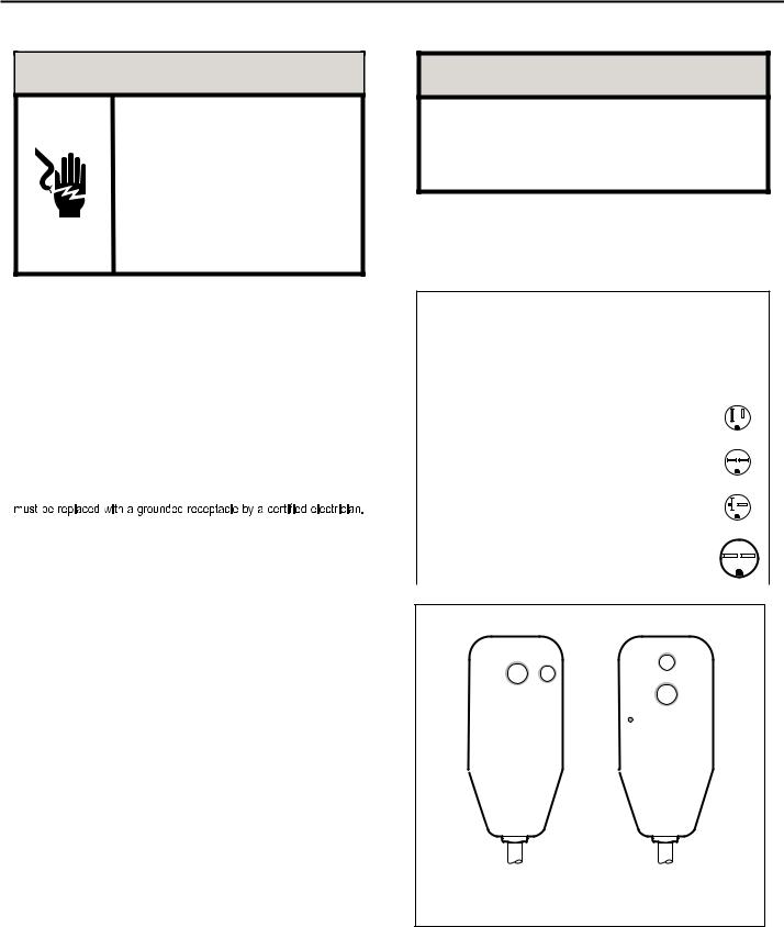
Test the power cord
All Friedrich room air conditioners are shipped from the factory with a Leakage Current Detection Interrupter (LCDI) equipped power cord. The LCDI device on the end of the cord meets the UL and NEC requirements for cord connected air conditioners.
To test your power supply cord:
1.Plug power supply cord into a grounded 3 prong outlet.
2.Press RESET (See Figure 1).
3.Press TEST, listen for click; the RESET button trips and pops out.
4.Press and release RESET (Listen for click; RESET button latches and remains in). The power cord is ready for use.
Table 1.
|
CIRCUIT RATING |
REQUIRED |
||||||||||
|
OR TIME DELAY |
WALL |
||||||||||
MODEL |
FUSE |
RECEPTACLE |
||||||||||
|
AMP |
VOLT |
NEMA |
|
|
|
|
|
|
|
|
|
|
NO. |
|
|
|
|
|
|
|
|
|
||
|
|
|
|
|
|
|
|
|
|
|
|
|
SS08, SS10 |
15 |
125 |
5-15R |
|
|
|
|
|
|
|
|
|
SS12, SS14 |
|
|
|
|
|
|
|
|
|
|||
|
|
|
|
|
|
|
|
|
||||
YS10, SM15 |
|
|
|
|
|
|
|
|
|
|
|
|
SS12, SS15 |
15 |
250 |
6-15R |
|
|
|
|
|
|
|
|
|
SM18, SM21 |
|
|
|
|
|
|
|
|
|
|||
|
|
|
|
|
|
|
|
|
|
|
|
|
|
|
|
|
|
|
|
|
|
|
|
|
|
SM24, SL28 |
|
|
|
|
|
|
|
|
|
|
|
|
ES12, ES15 |
20 |
250 |
6-20R |
|
|
|
|
|
|
|
|
|
|
|
|
|
|
|
|
|
|
||||
YS12 |
|
|
|
|
|
|
|
|
|
|
|
|
|
|
|
|
|
|
|
|
|
|
|
|
|
SL36, EM18 |
|
|
|
|
|
|
|
|
|
|
|
|
EM24, EL36 |
30 |
250 |
6-30R |
|
|
|
|
|
|
|
|
|
|
|
|
|
|
|
|
|
|
||||
YM18, YL24 |
|
|
|
|
|
|
|
|
|
|
|
|
|
|
|
|
|
|
|
|
|
|
|
|
|
Figure 1
RESET TEST
WARNING
TEST BEFORE EACH USE
1.PRESS RESET BUTTON
2.PLUG LCDI INTO POWER RECEPTACLE
3.PRESS TEST BUTTON,
RESET BUTTON SHOULD
 POP UP
4.PRESS TEST BUTTON, FOR USE
DO NOT USE IF ABOVE TEST
FAILS
WHEN GREEN LIGHT IS ON
IT IS WORKING PROPERLY
TEST
RESET
WARNING
TEST BEFORE EACH USE
1.PRESS RESET BUTTON
2.PLUG LCDI INTO POWER RECEPTACLE
3.PRESS TEST BUTTON, RESET BUTTON SHOULD POP UP
4.PRESS TEST BUTTON, FOR USE
DO NOT USE IF ABOVE TEST FAILS
WHEN GREEN LIGHT IS ON IT IS WORKING PROPERLY
15/20A LCDI Device |
30A LCDI Device |
FRR001
6
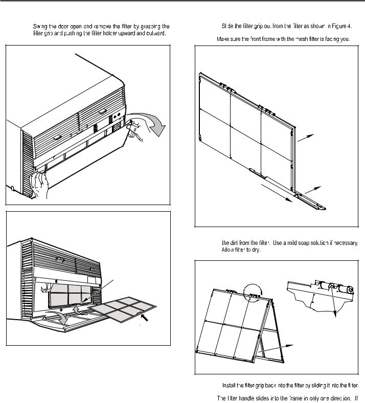
Standard Filter Cleaning / Installation Instructions
STEP 1.
Figure 2 |
FRR071 |
Figure 3 |
FILTER |
GRIP |
HANDLE |
FRR052 |
STEP 2. |
NOTE: |
Figure 4 |
FILTER |
FILTER |
GRIP |
FRR047 |
STEP 3. Swing the front frame open. Clean the front frame by washing
Figure 5 |
A |
TOP TAB |
FRONT |
FRAME WITH |
STANDARD |
MESH FILTER |
FRR048 |
STEP 4. |
NOTE: |
the tab in the frame stops the handle from sliding in, slide the handle from the other direction. DO NOT FORCE THE HANDLE INTO
THE FRAME.
STEP 5.  the inside of the front door.
7
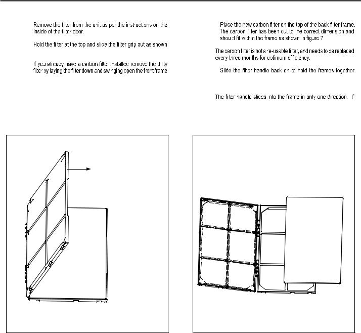
Premium Carbon Filter Installation Instructions
STEP 1. |
STEP 4. |
STEP 2. |
|
in Figure 4. |
NOTE: |
STEP 3. |
|
|
STEP 5. |
as shown in Figure 6.
NOTE: Make sure the frame with the mesh is facing towards you.
and slide the assembly into the unit as per the instructions on the door.
NOTE:
the tab in the frame stops the handle from sliding in, slide the handle from the other direction. DO NOT FORCE THE HANDLE INTO
|
THE FRAME. |
Figure 6 |
Figure 7 |
FRONT FRAME WITH |
|
MESH FILTER |
|
FRR050 |
FRR051 |
8

THIS PAGE INTENTIONALLY LEFT BLANK
9
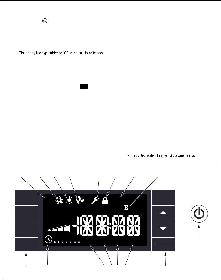
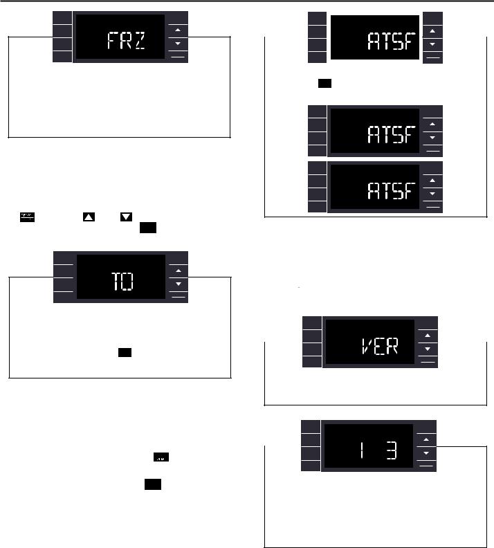
Control Panel Operation
Let’s check out how to control your air conditioner. On the control panel, just to the left of the POWER , is a liquid crystal display (LCD). All of the control panel function buttons and mode icons can be viewed in Figure 8.
POWER ON – Press the  button to turn on the air conditioner. The power button will illuminate to indicate the power is on. The backlight on the power switch will automatically dim to 20% intensity after 15 seconds of inactivity. The remote control can also be used to turn power ON / OFF (See Remote Control).
DISPLAY –
light. The back light has an automatic two (2) step dim function. After 15 seconds of inactivity, the display dims to 20% intensity. After an additional 120 seconds, the display switches off. Touching buttons will automatically bring the display to full brightness.
There are four control push buttons on each side of the display.
SYSTEM BUTTON – Allows the user to sequentially select, 
 Cool
Cool  , HEAT
 , and FAN ONLY
  operation. Press the
 button and the display advances to the next mode. A new icon appears. At the same time, the mode displays for two (2) seconds, then returns the display to the temperature set point for modes other than FAN. Note that when the heating function is not available, the system will automatically skip the
HEAT and
and 
 modes.
NOTE: After the compressor stops the fan will continue to operate for 30 seconds.
FAN MODE BUTTON – Selects between automatic 
 or
or 

 operation. In the
 mode, the fan only turns on and off when the compressor operates or the heat function is enabled.
In the FAN ONLY Mode, 
 is not available. The display indicates

 . In the

 mode, fans speed is determined by your selection on the
  button.
FAN SPEED BUTTON – Used to sequentially select between fan speeds. Depending on your model, you can select between LOW, MED, HIGH, and MAX and AUTO. Max setting not on SL, EL, YL or cool plus models). When the  button is pressed, the fan speed is temporarily displayed in the display window, plus a fan speed icon (triangle) changes to indicate the new speed level. W hen auto is selected, fan speed automatically varies depending on the set temperature on the control panel and the actual room temperature. Let me explain. Say for example you’re working in your garage and you need to open the big door for several minutes. The air conditioner will sense a wide difference between the set temperature and the actual room temperature when this occurs the system fan speed increases to MAX. The fan speed decreases (in step) as the temperature difference decreases. When the set point temperature is reached the FAN speed returns to the original setting.
SCHEDULE BUTTON – The 
 button turns the schedule function on and off. The current day of the week is indicated as a dot underneath the day symbol. Pressing the
 button a second time turns the schedule function off. The schedule function comes preprogrammed with recommended energy savings values (Addendum 1). The values may be changed through the schedule program function (See Programmable Thermostat).
UP AND DOWN ARROWS – Pressing either (UP) or
 (DOWN) button changes the desired room temperature. The factory preset lower and upper limits are 60° F (16° C) and 99° F (37° C). These buttons are also used to navigate between function options when using the User Menu or Maintenance Mode.
BACK BUTTON – This button is used after a menu item has been selected. It takes the user back to the previous menu level.
DISPLAY/ENTER BUTTON – This button is used in conjunction with User menu and Maintenance Mode operation to select items.
This button may also be used alternately to display the ROOM TEMPERATURE and TIME. If the display is left inactive for 10 seconds it will reset to the TEMPERATURE SET POINT.
|
|
|
|
|
|
|
ALERTS |
|
|
|
|
Figure 8 |
|
|
|
FAN |
|
|
FRONT |
|
|
|
|
AUTO |
COOL |
HEAT |
ONLY |
MAINTENANCE |
PANEL |
FILTER |
|
|
|||
MODE |
MODE |
MODE |
MODE |
REQUIRED |
LOCK |
MAINTENANCE |
WAIT |
|
|||
SYSTEM |
|
|
|
|
|
CHECK |
ON |
EXIT |
BACK |
|
|
|
AUTO |
|
|
|
|
|
|||||
|
|
|
|
|
|
|
|
|
|
|
|
|
|
|
|
|
|
|
FILTER |
OFF |
RESET |
|
|
FAN |
|
|
AUTO |
|
OUTDOORTEMP |
|
|
|
|
|
|
|
|
|
ROOM TEMP |
|
HEAT -> SET POINT<- COOL |
|
|
||||
|
|
|
|
|
|
|
|||||
|
|
|
|
|
|
|
|
||||
MODE |
|
|
CONTINUOUS |
|
|
|
|
F |
|
|
|
|
|
|
|
|
|
|
|
|
|||
|
|
|
|
|
|
|
|
|
|
|
|
|
|
|
|
|
|
|
|
|
A |
|
|
|
|
|
|
|
|
|
|
|
M |
|
|
FAN |
|
|
AUTO |
|
|
|
|
|
P |
|
|
|
|
|
|
|
|
|
|
|
|
|
|
SPEED |
|
|
|
|
|
|
|
|
M |
|
|
|
|
|
|
|
|
|
|
|
|
|
|
|
|
|
|
|
|
|
|
|
C |
|
|
|
|
|
M T W T F S S |
WAKE |
AWAY |
RETURN |
NIGHT |
DISPLAY |
POWER |
||
|
|
|
|
|
|||||||
SCHEDULE |
|
|
|
|
|||||||
|
|
|
|
|
|
|
|
|
|
||
|
|
|
|
|
|
|
|
|
|
ENTER |
|
BUTTONS |
SCHEDULE |
|
|
SCHEDULE |
|
|
BUTTONS |
|
|||
|
|
ON/OFF |
|
|
PERIODS |
|
|
|
|
||
|
|
|
|
|
|
|
|
|
|
|
FRR002 |
10 |
|
|
|
|
|
|
|
|
|
|
|
CHECK FILTER |
|
|
|
|
|
||
appears on screen. The word “ |
|
” appears next to the |
|
button. |
|||
|
|
|
|
|
|
|
|
The |
|
alert is issued when the fan run time is greater than 500 hours. |
|||||
This alert may be reset by the user (Refer to Special Functions, Filter Reset).
MAINTENANCE REQUIRED – When maintenance is required, a service icon  appears on screen. This icon will not be dismissed until maintenance
has been performed. If the service icon
the icon  is on standby the system has sensed an abnormal condition.
is established the service icon  goes away.
WAIT – The WAIT icon  illuminates when the compressor lockout is active. Whenever the compressor shuts off, system pressures must be allowed to equalize. At this time, an internal timer begins a count-down from up to 240 seconds. If a demand for heat or cool occurs during this count-down the WAIT icon
  displays letting you know that the compressor will not operate until the count-down has completed. This timer prevents damage to the unit if it tries to start too quickly after it stops running. Normally the WAIT icon
  is off. Once the timer has cleared, the air conditioner will heat or cool based on the temperature setting. Electric heat is not affected by this timer.
PROTECTION ALERT (FREEZE) – If the room freeze protection is active, the display indicates this by showing Room Freeze Protection "FRZ". Once
temperature is less than 40° F (4° C), and the air conditioner is equipped with electric heat, the room freeze protection will activate. The air conditioner will run high fan and electric heat until the room temperature reaches 46° F (8° C). Pressing the  button delays the freeze protection function
LOW BATTERY – When the battery is low a warning display 

 will be inserted before other messages such as “COOL”. If the Low Battery

 alert is on, the battery in the control unit must be changed. Refer to the changing the battery procedure. Once the battery is changed, the alert message will go off. Refer to Troubleshooting Tips. Under normal conditions the battery life should be greater than 7 years.
Special Functions
PANEL LOCK  – The front panel push buttons can be locked to prevent inadvertent operation. To lock the front panel, press and hold the SCHEDULE +
  buttons for three (3) seconds. A double beep indicates your mode change was successful and a
  icon appears on the display. To unlock the display, press and hold the
 +
+ 
 buttons for three (3) seconds.
The  icon will no longer be visible.
FILTER RESET – |
|
|
|
|
|
icon displays, the timer may be reset by pressing |
|||||
|
|||||||||||
|
|
|
|
|
|
||||||
and holding the |
|
button for three (3) seconds. A beep indicates the |
|||||||||
|
|
|
|
|
|
|
|
|
icon and the word " |
RESE T |
" will |
|
system timer was reset and the |
||||||||||
no longer be visible. |
|
|
|
|
|
|
|||||
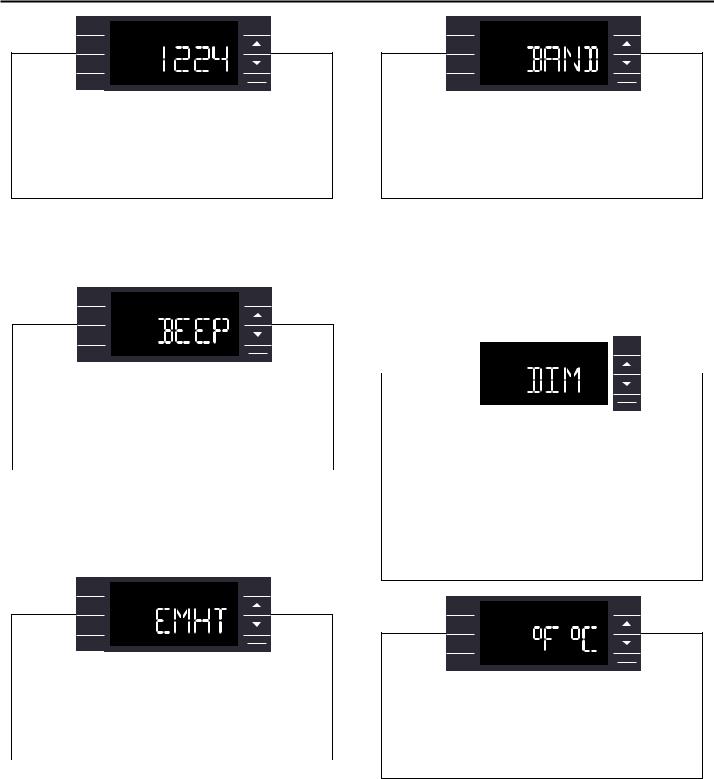
USER MENU FUNCTIONS – The User Menu Functions allows you to change the following selections: Set TIME, 12/24 Hour Clock Format, BEEP ON / OFF, DIM ON / OFF, Emergency Heat (EMHT) ON / OFF, Auto BAND Adjust, F/ C Select, FRZ ON / OFF, the Automatic Temperature Sensing Feature and Temp Offset.
To enter the User Menu, press and hold 
 for 3 seconds, the TIME selection appears. Use the
  (UP) or
  (DOWN) buttons to scroll through the User Menu. Press the
  button to enter the displayed function. If left inactive for 15 minutes the User Menu display will no longer be visible and it returns to normal operation mode display. To manually exit the User Menu, press the
  button.
|
|
|
|
|
|
|
|
|
|
|
|
|
|
|
|
|
|
|
|
|
|
|
|
|
|
|
|
|
|
|
|
|
|
|
|
|
|
|
|
|
|
|
|
|
|
|
|
|
|
|
|
|
|
THE HOUR DIGITS FLASH FIRST. THE USER PRESSES THE |
|
|
OR |
|
|
|
|
||||||||||
|
|
|
|
|
|
||||||||||||
TO CHANGE THE HOURS. TO CHANGE AM-PM, THE HOURS MUST BE |
|||||||||||||||||
|
|
|
|
|
|
|
|
|
|
|
|
||||||
ADVANCED 12 HOURS. PRESS THE |
|
|
KEY TO CHANGE TO THE |
||||||||||||||
|
|
|
|
|
|
|
|
||||||||||
MINUTES. TO EXIT THE SELECTION PROCESS, USER PRESSES THE |
|
|
|||||||||||||||
KEY WHICH WILL GO TO THE TIME SCREEN. |
|
|
|
|
|
|
|
||||||||||
|
|
|
|
|
|
|
|
|
|
|
|
|
|
||||
THE MINUTES DIGITS FLASH. THE USER PRESSES THE |
|
|
OR |
|
|
|
|
|
|||||||||
|
|
|
|||||||||||||||
|
|
|
|
|
|
|
|
|
|
|
|||||||
TO CHANGE THE MINUTES. PRESS THE |
|
|
KEY TO CHANGE THE DAYS. |
||||||||||||||
TO EXIT THE SELECTION PROCESS, THE USER PRESSES THE |
|
|
|
|
KEY |
||||||||||||
|
|
|
|
||||||||||||||
WHICH WILL GO TO THE TIME SCREEN. |
|
|
|
|
|
|
|
|
|
|
|
|
|
|
|||
THE DOT UNDERNEATH THE DAYS OF THE WEEK BEGINS TO BLINK TO INDICATE WHICH DAY IT IS. IF THE USER HAS NOT SET THE DATE BEFORE, THE DOT STARTS ON MONDAY. IF THE USER IS MAKING A CORRECTION TO PREVIOUSLY SET INFORMATION THE DOT APPEARS UNDER WHICHEVER DAY THE UNIT THINKS IT IS. THE USER CAN PRESS  OR
OR  TO MOVE THE DOT LEFT OR RIGHT (RESPECTIVELY) ALONG THE WEEK. THE USER PRESSES
  TO LOOP BACK TO THE HOURS SETTING. TO EXIT THE SELECTION PROCESS, THE USER PRESSES THE
  KEY WHICH WILL GO TO THE TIME SCREEN.
TUESDAY HAS BEEN SELECTED. THE USER PRESSES  TO LOOP BACK TO THE HOURS SETTING. TO EXIT THE SELECTION PROCESS AND ACCEPT THE CHANGES, THE USER PRESSES THE BACK KEY WHICH WILL GO TO THE TIME SCREEN.
FRR062
TIME SETTING – When in the User Menu, on the Control Panel, use the
|
(UP) and |
|
(DOWN) to select TIME. Push |
|
, the hours segment |
||||||
|
|
|
|
|
|
|
|
|
|
|
|
|
|
|
|
|
(UP) and |
|
(DOWN) to set the hour, then push |
||||
|
|
|
|
|
|
|
|
(UP) and |
|
(DOWN) |
|
|
|
|
|
|
|
|
|
|
|||
to set the minutes, then push  .
.
NOTE: If the AM or PM indicator is incorrect, push  until the hours
 (UP) or
  (DOWN) to advance the hour segment 12 hours, then push
  . The day of the week
displays. Use the  (UP) or
  (DOWN) to select the current day. Press the
  key to save and go back to the TIME screen.
Press  (UP) to go to the next menu 1224.
NOTE: Pressing the  button again will exit the user menu function mode. Or simply leave the control inactive for 15 seconds and the control will return back to normal operation.
11
SYSTEM |
EXIT |
BACK |
|
FAN
MODE
FAN
SPEED
DISPLAY
SCHEDULE
ENTER
USER PRESSES  OR
OR  TO TOGGLE THE FORMAT BETWEEN 12HR AND 24HR DISPLAY. TO EXIT THE SELECTION PROCESS AND ACCEPT THE CHANGE, PRESS THE
  KEY.
KEY.
FRR063
CLOCK TYPE – You may select between a 12 hr and 24 hr clock. When 1224 is displayed press the  key then press
  (UP) or
  (DOWN) to toggle between 12 hr and 24 hr clock. To accept the change, press the
  key to return to the 1224 screen. Press the
  (UP) to go to the next menu BEEP.
SYSTEM |
EXIT |
BACK |
FAN
MODE
FAN
SPEED
DISPLAY
SCHEDULE
ENTER
USER PRESSES OR
OR TO TOGGLE BETWEEN BEEP ON AND BEEP OFF. PRESS THE
  KEY TO ACCEPT THE CHANGE AND EXIT THE SELECTION PROCESS.
FRR064
AUDIBLE ALERTS – You can select to have the control beep when entering menus. When BEEP is displayed press the  key then press
  (UP) or
  (DOWN) to toggle between ON and OFF. To accept the change, press the
  key to return to the BEEP screen. Press the
  (UP) to go to the next menu EMHT on Kühl+ models or F C for Kühl models.
SYSTEM |
EXIT |
BACK |
FAN
MODE
FAN
SPEED
DISPLAY
SCHEDULE
ENTER
USER PRESSES  OR
OR  TO TOGGLE BETWEEN EMERGENCY HEAT ON AND EMERGENCY HEAT OFF. PRESS THE
  KEY TO ACCEPT THE CHANGE AND EXIT THE SELECTION PROCESS.
FRR065
EMERGENCY HEAT – The Kühl+ heat pump models (YS, YM, YL) have a special feature that is designed to keep the unit providing heat.
When EMHT is displayed press the  key then press
  (UP) or
  (DOWN) to toggle between ON and OFF.
To accept the change, press the  key to return to the EMHT screen. Press the
  (UP) to go to the next menu BAND.
In the unlikely event of a compressor failure, the heat pump unit may be switched to operate in the electric heat mode only until repairs can be made.
SYSTEM |
EXIT |
BACK |
|
FAN
MODE
FAN
SPEED
DISPLAY
SCHEDULE
ENTER
THE MENU ALLOWS THE USER TO ADJUST THE MINIMUM SPREAD BETWEEN THE AUTO COOL SET POINT AND THE AUTO HEAT SET POINT. PRESS THE  OR
OR  KEY TO ADJUST. THE ADJUST RANGE IS 3 TO 10.
FRR066
AUTO CHANGEOVER ‘DEAD BAND’ – A buffer Zone between heating and cooling in which no conditioning occurs. For Kühl+ models with the auto changeover feature you can select the temperature band between heating and cooling. From the factory the band is set at 3° F (-16° C). The band is adjustable from 3° F (-16° C) to 10° F (-12° C). When BAND is displayed
press the |
|
|
key then press |
|
(UP) or |
|
(DOWN) to toggle between |
|||||||
3 and 10. To accept the change, press the |
|
|
key to return to the BAND |
|||||||||||
|
|
|||||||||||||
|
|
|||||||||||||
screen. Press the |
|
(UP) to go to the next menu F C. |
||||||||||||
|
|
|
|
|
|
|
|
|
|
|
|
|
BACK |
|
|
|
|
SYSTEM |
|
|
|
|
|
EXIT |
|
||||
|
|
|
|
|
|
|
|
|
|
|
||||
|
|
|
FAN |
|
|
|
|
|
|
|
|
|
||
|
|
|
MODE |
|
|
|
|
|
|
|
|
|
||
|
|
|
FAN |
|
|
|
|
|
|
|
|
|
|
|
|
|
|
|
|
|
|
|
|
|
|
|
|
||
|
|
|
|
|
|
|
|
|
|
|
|
|||
|
|
|
SPEED |
|
|
|
|
|
|
|
|
|
||
|
|
SCHEDULE |
|
|
|
|
|
|
|
DISPLAY |
||||
|
|
|
|
|
|
|
|
|
ENTER |
|||||
|
|
|
|
|
|
|
|
|
|
|
|
|
||
|
|
|
|
|
|
|
|
|
|
|
|
|
|
|
USER PRESSES  OR
OR  TO SELECT BETWEEN AUTO, DM 20, OFF. PRESS THE
  KEY TO ACCEPT THE CHANGE AND EXIT THE SELECTION PROCESS.
THE DIM AUTO AUTOMATICALLY DIMS THE DISPLAY AND THEN TURNS IT OFF AFTER A PERIOD OF TIME. THE DIM 20 SETTING BEHAVIOR IS SIMILAR TO AUTO, BUT PREVENTS THE DISPLAY FROM TURNING OFF. MINIMUM BRIGHTNESS IS 20%. THE DIM OFF SETTING FORCES THE DISPLAY TO RUN AT FULL BRIGHTNESS.
FRR067
SYSTEM |
EXIT |
BACK |
|
FAN
MODE
FAN
SPEED
DISPLAY
SCHEDULE
ENTER
USER PRESSES  OR
OR  AT THE SAME TIME TO TOGGLE BETWEEN FAHRENHEIT OR CELSIUS AS THEIR TEMPERATURE UNIT OF CHOICE. PRESS THE
  KEY TO ACCEPT THE CHANGE AND EXIT THE SELECTION PROCESS.
FRR068
FAHRENHEIT / CELSIUS SELECTION – You may select between displaying temperature in F or C. When F C is displayed press the  key then press
  (UP) or
  (DOWN) to toggle between F and C. To accept the change, press the
  key to return to the F C screen. Press the
  (UP) to go to the next menu FRZ.
12
SYSTEM EXIT BACK
FAN
MODE
FAN
SPEED
SCHEDULE |
DISPLAY |
|
ENTER |
||
|
User presses or
or to select between Freeze Protection On & Freeze Protection Off. Press the
  key to accept the change and exit the selection process.
FRR069
Freeze Protection – The Kühl+ models have a special feature that is designed to keep the interior space above freezing by energizing the electric heater anytime the indoor room temperature falls to 40° F (4° C). With the freeze protection feature turned on, when the unit senses the indoor temperature fall to 40° F (4° C) the unit will run the heater and high
fan until the space reaches 46° F (8° C) |
When FRZ is displayed press |
||
the |
key then press |
(UP) or |
(DOWN) to toggle between ON |
and OFF. To accept the change, press the 
 key to return to the FRZ screen. Press the
  (UP) to go to the next menu TO.
SYSTEM EXIT BACK
FAN
MODE
FAN
SPEED
SCHEDULE |
DISPLAY |
|
ENTER |
||
|
User presses  or
or  to increment/decrement the temperature offset (TO) for the room temperature sensor. (Maximum offset = +/- 8 degrees F). Press the
 key to accept the change and exit the selection process
FRR070
Temperature Offset – In some cases the built in thermostat on the unit may not display the temperature as it is felt in the room. This can be caused by many things including the size of the unit, the heat load on the room or other factors. Friedrich allows you to select the appropriate temperature offset to make the temperature readout as accurate as possible for your application. In many cases the factory 0° F (-18° C) offset will provide an accurate temperature readout. To change the offset follow these instructions. When TO is displayed press the 
 key then press
  (UP) or
  (DOWN) to toggle between 0° F (-18° C) and 8° F (-13° C). In most instances an offset from 0° F (-18° C) to 2° F (-17° C) is all that is necessary. To accept the change, press the
 key to return to the TO screen. Press the
  (UP) to go to the next menu TIME.
You may cycle through the menus using the |
|
(UP) or |
|
(DOWN) keys |
|
|
|||
to access any of the menus. |
|
|
|
|
SYSTEM |
|
EXIT |
BACK |
|
|
FANF |
|
|
|
|
|
MODE |
|
|
|
|
|
|
|
|
|
|
|
FANF |
|
|
|
|
|
|
|
|
|
|
|
SPEED |
|
|
|
|
|
SCHEDULE |
Y |
|
DISPLAY |
|
|
R |
|
ENTER |
FRR072 |
||
|
|
|
|||
|
|
|
|
||
User presses  or
or  to select between ATSF On or Off.
Press the 
 key to accept the change and exit the selection process.
SYSTEM |
EXIT |
BACK |
|
|
OFF |
|
|
FAN |
|
|
|
MODE |
|
|
|
FAN |
|
|
|
SPEED |
|
|
|
SCHEDULE |
|
DISPLAY |
|
|
ENTER |
FRR073 |
|
|
|
||
|
|
|
|
SYSTEM |
ON EXIT |
BACK |
|
FAN |
|
|
|
MODE |
|
|
|
FAN
SPEED
SCHEDULE |
DISPLAY |
|
|
ENTER |
FRR074 |
||
|
|||
|
|
Automatic Temperature Sampling Feature - The automatic temperature sampling feature maintains a balanced temperature throughout the room by circulating the air for 30 seconds once every 9 minutes that the unit is not running and set to cooling or heating mode. By circulating the air the unit can detect hot or cold area in the room and operate the unit to cool or warm the room as necessary. This function is only available when the fan mode is set to ‘AUTO’ and in COOL or HEAT mode. (Heating function only available on Kuhl+ units)
SYSTEM |
EXIT |
BACK |
||
FAN |
|
|
|
|
MODE |
|
|
|
|
|
|
|
|
|
FAN |
|
|
|
|
SPEED |
|
|
|
|
SCHEDULE |
|
DISPLAY Y |
||
|
ENTER |
|||
|
|
|
||
For display only. No user selectable options.
FRR075
F |
|
|
|
SYSTEM |
EXIT |
BACK |
|
F |
|
|
|
FAN |
|
|
|
MODE |
|
|
|
|
|
|
|
FAN |
|
|
|
SPEED |
|
|
|
SCHEDULE |
|
DISPLAY |
|
|
ENTER |
||
|
|
|
|
Firmware Version - When VER is displayed press Display / Enter key. The firmware version is displayed as left digit (Major) and right digit (Minor). This version number should be used along with Model and Serial numbers for service.
FRR076
13
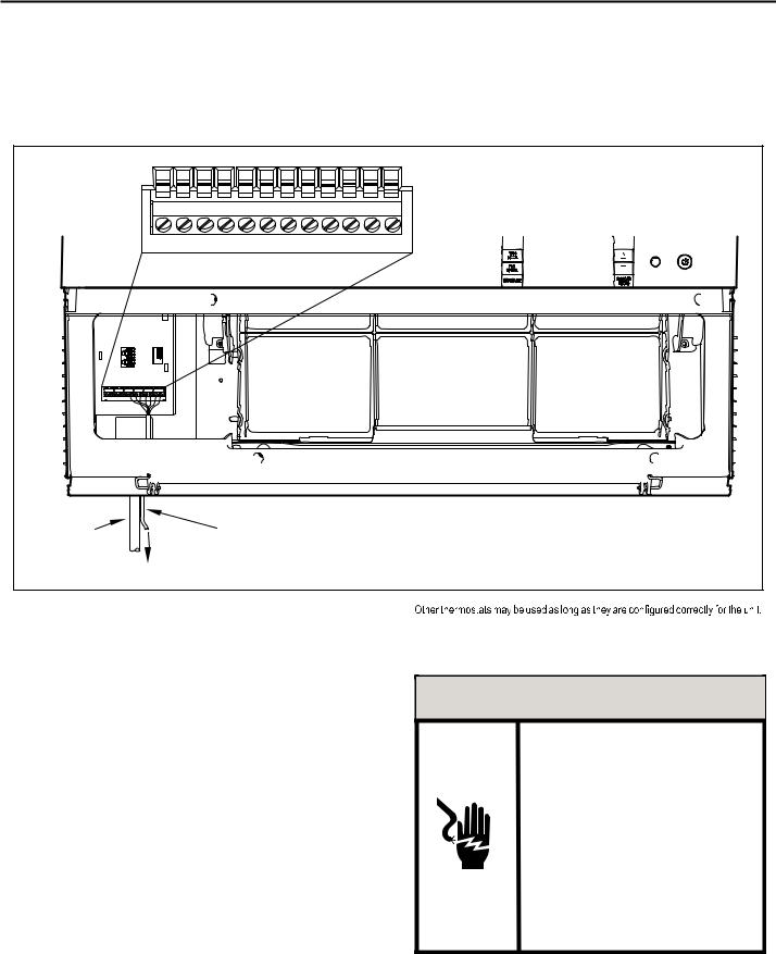
Add a Remote Thermostat
REMOTE THERMOSTAT – An external thermostat may be added to the air conditioner to provide remote temperature sensing and control. The thermostat interface connector is located on the panel behind the front grille. To enable the remote thermostat operation, remove the jumper
4.Changing modes on the remote thermostat will not illuminate the Control Panel LCD.
Remote Thermostat Selection
Friedrich recommends the use of either the RT4 or RT5. The RT4 is a digital display thermostat with single speed fan control. The RT5 features a digital display, two fan speed selection, battery backup and backlight.
Figure 9 |
THERMOSTAT CONNECTOR |
FP F2 F1 D2 D1 C GH GL B Y W R
POWER |
THERMOSTAT WIRE ROUTING USE #18 |
CORD |
AWG COLORED THERMOSTAT WIRE |
TO REMOTE THERMOSTAT
FRR004
Table 2 |
Interface Definitions |
|
|
|
|
|
TERMINAL CODE |
WIRE CONNECTION FUNCTION |
|
|
|
|
C |
COMMON GROUND TERMINAL |
|
|
|
|
GH |
CALL FOR HIGH FAN |
|
|
|
|
GL |
CALL FOR LOW FAN |
|
|
|
|
B |
CALL FOR HEAT PUMP REVERSING VALVE |
|
|
|
|
Y |
CALL FOR COMPRESSOR |
|
|
|
|
W |
CALL FOR HEATING |
|
|
|
|
R |
24V POWER FROM ELECTRONIC CONTROL TO |
|
WALL THERMOSTAT |
|
|
|
|
|
|
|
between terminals FP & F2 on the terminal block. Connect the thermostat using Figure 9 and Table 2 as a guide.
If you connect an external thermostat, all Control Panel buttons will be disabled with the following exception:
1.Maintenance commands (double button press & single button extended press).
2.The 
 button for Freeze protection.
3.First Button pushed, illuminate the LCD.
For cooling models a single stage cooling thermostat with C, R, G, Y terminals must be used. For electric heat ‘E’ models a single stage heating and cooling thermostat with C, R, G, Y, W terminals must be used. For heat pump ‘Y’ models a single stage heating and cooling thermostat with C, R, G, Y, W, B terminals must be used.
 CAUTION
IT IS THE INSTALLER’S RESPONSIBILITY TO
ENSURE THAT ALL CONTROL WIRING
CONNECTIONS ARE MADE IN ACCORDANCE
WITH THE INSTALLATION INSTRUCTIONS.
IMPROPER CONNECTION OF THE THERMOSTAT
CONTROL WIRING AND/OR TAMPERING WITH
THE UNIT’S INTERNAL WIRING CAN VOID THE
EQUIPMENT WARRANTY.
FAILURE TO FOLLOW THESE INSTRUCTIONS CAN
RESULT IN PERSONAL INJURY AND DAMAGE TO
PRODUCT OR OTHER PROPERTY.
14
Remote Control Operation
REMOTE CONTROL – Refer to Figures 11 and 12 during operation description.
GETTING STARTED – Install two (2) AAA batteries in the battery compartment located on the back of the unit.
OPERATION – The remote control should be within 25 feet of the air conditioner for operation (Refer to Figure 10 for effectiveness). Press the  button to turn the remote on. The remote will automatically power off after 15 seconds if the buttons are not being pressed. The remote must be on to control the unit.
POWER BUTTON – Turns remote and unit on and off.
SYSTEM BUTTON – Allows the user to sequentially select, 
 Cool
Cool  , HEAT
 , and FAN ONLY
 operation. When the button is pressed, the display indicates which mode has been selected via a display message. Note that when the heating function is not available, the system will automatically skip the HEAT and AUTO modes.
FAN MODE BUTTON – Selects between automatic (
 ) or
) or

 operation. In the AUTO mode, the fan only turns on and off when the compressor operates or the heat function is enabled.
NOTE: AUTO is not available in the FAN ONLY Mode, the display indicates 

 . In the

 mode, fan speed is determined by your selection on the
 button.
FAN SPEED BUTTON – Used to sequentially select new fan speed, plus
AUTO operation. When the FA N button is pressed, the fan speed is
SPEED
temporarily displayed in the display window, plus a fan speed icon (triangle) changes to indicate the new speed level. Fan speed automatically varies depending on the set temperature on the control panel and the actual room temperature. Let me explain. Say for example you’re working in your garage and you need to open the big door for several minutes. Since there is a big difference between your set temperature and the actual room temperature the system fan speed increases to MAX. It remains at this speed until the room temperature matches the set temperature.
SCHEDULE BUTTON – The SCHEDULE button turns the schedule function on and off. Pressing the SCHEDULE button a second time turns the schedule function off. Only the schedule icon will be displayed.
UP AND DOWN ARROWS – Pressing either the  (UP) or
  (DOWN) button changes the desired room temperature. The factory preset lower and upper limits are 60° F (16° C) and 99° F (37° C). These buttons are also used to navigate between function options when using the User Menu or Maintenance Mode.
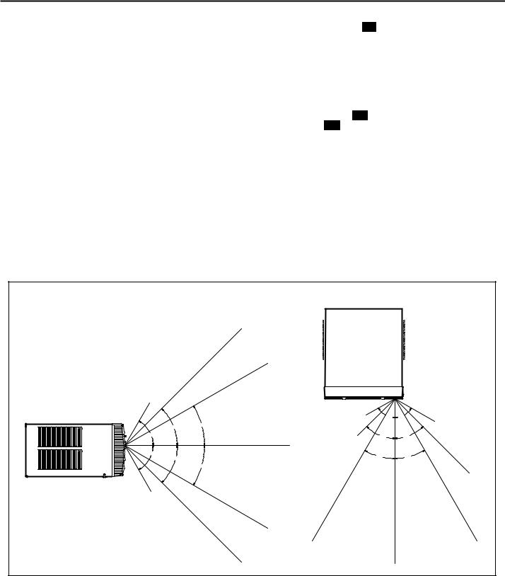
Remote Effectiveness
HAND HELD REMOTE – Has an operating range of up to 25 ft. The infrared remote control signal must have a clear path to transmit the command to the air conditioning unit. The remote signal has some ability to "bounce" off of walls and furniture similar to a television remote control. The diagram below shows the typical operating range of the control in a standard room with 8 ft high ceilings.
Figure 10 |
|
|
|
|
TOP VIEW |
|
|
|
25FT |
|
|
|
25FT |
|
|
7.5FT |
|
|
|
SIDE VIEW |
4FT |
60° |
60° |
|
|||
|
30° |
|
6FT |
45° |
|
|
|
|
|
|
|
60° |
8FT |
45° |
45° |
|
|||
|
|
|
|
|
25FT |
|
|
60° |
|
30° |
|
45° |
|
30° |
|
|
|
|
|
|
30° |
|
|
|
|
|
16FT |
8FT |
|
|
|
|
25FT |
|
|
|
25FT |
|
25FT |
|
25FT |
|
25FT |
|
|
|
|
|
|
|
FRR046 |
|
|
|
15 |
Figure 11
 DISPLAY
SYSTEM |
FAN MODE |
|
POWER |
TEMPERATURE |
TEMPERATURE |
UP |
DOWN |
SCHEDULE |
FAN SPEED |
FRR005
Figure 12
AUTO |
COOL |
HEAT |
FAN ONLY |
ICON |
ICON |
ICON |
ICON |
SYSTEM
MODE
°F / °C  ICONS
ICONS
FAN
MODE
FAN
SPEED
SCHEDULE |
2 X 16 SEGMENT |
|
ICON |
||
DISPLAY |
||
|
FRR006
16
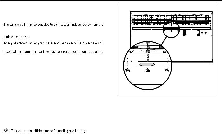
Airflow Selection and Adjustment
Air flow direction adjustment
left or right side of the discharge opening. Each of the banks of louvers can be directed left, right, up or down in order to achieve the most optimum
move it in the direction that you would like the air to be directed. Please
louvers than the other.
Fresh air and exhaust control
Your air conditioner has the ability to bring fresh air into the room or exhaust stale air out of the room. The control slide is found on the upper part of the unit (See Figure 13).
TO BRING IN FRESH AIR – Move the lever to the FRESHAIR  position which allows outside air to enter the room. This is useful in fall and spring as a means of bringing in fresh outside air when using FAN ONLY . It can also be used in the summer with the compressor in the Cooling Mode if you wish.
TO EXHAUST INDOOR AIR – Move the lever to the EXHAUST  position. This will allow stale air to be expelled to the outside of the dwelling. This is especially handy in the spring or fall when indoor air tends to get stale, or after a social gathering involving smokers, or to remove cooking odors.
BEST PERFORMANCE – Move the lever to the RE-CIRCULATE POSITION
Figure 13 |
FRR008 |
17
Installation Instructions
READ THIS FIRST! Electrical Requirements
 WARNING
Electrical Shock Hazard
MAKE SURE YOUR ELECTRICAL RECEPTACLE HAS THE
SAME CONFIGURATION AS YOUR AIR CONDITIONER’S
PLUG. IF DIFFERENT, CONSULT A LICENSED ELECTRICIAN.
DO NOT USE PLUG ADAPTERS.
DO NOT USE AN EXTENSION CORD.
DO NOT REMOVE GROUND PRONG.
ALWAYS PLUG INTO A GROUNDED 3 PRONG OULET.
FAILURE TO FOLLOW THESE INSTRUCTIONS CAN RESULT IN
DEATH, FIRE, OR ELECTRICAL SHOCK.
IMPORTANT: Before you begin the actual installation of your air conditioner, check local electrical codes and the information below. Your air conditioner must be connected to a power source with the same alternating current (A.C.) voltage and amperage as marked on the name plate located on the chassis. Only A.C. can be used. Direct Current (D.C.) cannot be used.
CIRCUIT PROTECTION – Use on single outlet circuit only. An overloaded circuit will invariably cause malfunction or failure of an air conditioner, therefore, it is necessary that the electrical protection is adequate. Due to momentary high current demand when the air conditioner starts, use a "TIME DELAY" fuse or a HACR type circuit breaker. Consult your dealer or power company if in doubt.
Refer to the electrical name plate located on the air conditioner chassis (See page 2) to determine the correct fuse or circuit breaker amperage for your model (See Table 1 on Page 6 for electrical receptacle types).
The power cord has a plug with a grounding prong and a matching receptacle is required.
The following instructions are for standard chassis model groups
sizes listed in Table 3.
Table 3
MODEL DESIGNATION |
CABINET SIZE (H x W x D) |
|
|
SMALL CHASSIS - SS, |
15 15⁄16" X 25 15⁄16" X 29" (405 MM X |
ES, YS |
660 MM X 737 MM) |
|
|
MEDIUM CHASSIS - SM, |
17 15⁄16" X 25 15⁄16" X 29" (455 MM X |
EM, YM |
660 MM X 737 MM) |
|
|
LARGE CHASSIS - SL, |
20 3⁄16" X 28" X 35 1⁄2" (513 MM X 711 |
EL, YL |
MM X 851 MM) |
|
|
 WARNING
MOVING PARTS HAZARDS
*DO NOT OPERATE UNIT OUT OF SLEEVE OR WITH FRONT GRILLE REMOVED.
*DO NOT PLACE HANDS IN BLOWER OR
FAN BLADE AREAS.
FAILURE TO DO SO CAN RESULT IN
SERIOUS INJURY.
 CAUTION
Excessive Weight Hazard
USE TWO OR MORE PEOPLE WHEN
INSTALLING YOUR AIR CONDITIONER.
FAILURE TO DO SO CAN RESULT IN
BACK OR OTHER INJURY.
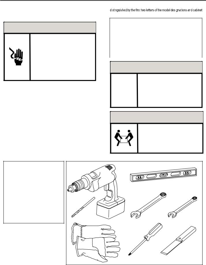
Recommended Tools
1.POWER DRILL
2.5/32" DRILL BIT
3.GLOVES
4.CARPENTERS LEVEL
5.5/16" WRENCH
6.1/4" WRENCH
7.#2 PHILLIPS SCREW DRIVER
8.PUTTY KNIFE OR (WOOD STIR STICK)
|
|
4 |
1 |
|
|
|
5/16 |
|
|
|
1 |
|
|
/4 |
|
5 |
6 |
|
5/16 |
/41 |
2 |
|
|
|
7 |
8 |
3 |
ITEMS NOT TO SCALE |
|
18
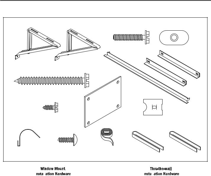
INSTALLATION HARDWARE AND ACCESSORY DETAIL
|
|
|
ITEM 2 |
ITEM 3 |
|
|
|
|
|
|
ITEM 1 |
|
|
|
|
|
|
ITEM 5 |
ITEM 6 |
|
ITEM 4 |
|
|
|
|
ITEM 7 |
ITEM 8 |
|
ITEM 9 |
|
|
|
||
ITEM 10 |
ITEM 11 |
ITEM 12 |
ITEM 13 |
ITEM 14 |
ITEMS NOT TO SCALE |
|
|
|
|
|
|
|
|
FRR009 |
|
|
|
|
|
|
|
|
|
|
|
|
ITEM |
|
DESCRIPTION |
QTY. |
||
NO |
|
|
|
|
|
|
|
|
|
|
|
|
WINGBOARD MOUNTING PARTS |
|
|||
8 |
WINGBOARD (MASONITE) |
1 |
|||
9 |
"J" TYPE SPEED NUT |
4 |
|||
10 |
WINGBOARD CLIP (SPRING STEEL) |
4 |
|||
11 |
SCREW, #8 X ½" PHILLIPS TRUSS HD. |
4 |
|||
|
|
|
|
|
|
|
WINDOW SEALING |
|
|||
12 |
SEALING GASKET (VINYL) |
1 |
|||
13 |
WINDOW SEAL GASKET (DARK FOAM) |
1 |
|||
14 |
CHASSIS SEAL GASKET (LIGHT FOAM) |
1 |
|||
|
|
|
|
|
|
|
SHELL MOUNTING PARTS |
|
|||
1 |
SUPPORT BRACKET |
2 |
|||
2 |
SCREW, 10-24 X 1" HEX HEAD |
4 |
|||
3 |
10-24 FLAT WELD NUT |
4 |
|||
4 |
SCREW, SHEET METAL #12 X 2" |
7 |
|||
|
|
|
|
|
|
|
WINGBOARD ANGLE MOUNTING |
|
|||
5 |
WINGBOARD ANGLE, TOP |
1 |
|||
6 |
WINGBOARD ANGLE, SIDE |
2 |
|||
7 |
SCREW, SHEET METAL #8 X 3! 8" |
2 |
|||
|
|
|
|
|
|
|
|
|
|
|
|
|
|
|
|
|
|
|
|
ITEM |
|
DESCRIPTION |
|
QTY. |
||
NO |
|
|
|
|
|
|
|
|
|
|
|
|
|
|
MOUNTING PARTS |
|
|
|||
4 |
SCREW, SHEET METAL #12A X 2” |
|
7 |
|||
14 |
CHASSIS SEAL GASKET (LIGHT FOAM) |
|
1 |
|||
|
|
|
|
|
|
|
NOTE: Kühl + m o dels do not c ome w it h w indow |
m ount ing |
|||||
|
components. When mounting a cooling and heating model |
|||||
|
a window installation kit must be purchased separately. |
|||||
KWIKS – For all ES and YS models.
KWIKM – For all EM and YM models.
KWIKL – For all EL and YL models.
19
Standard Window Installation
NOTE: Hardware and accessories used during installation are shown on page 18. Each part will be referred as Item No.
STEP 1. Remove the chassis Entrygard retainer by removing the far right screw (See Figure 14), save this screw to reattach the chassis retainer after installation (Step 12). Also, remove and discard the two retainer screws and washers located at the rear of the unit (See Figure 14).
|
CAUTION |
|
Handle Use |
|
USE HANDLE ON BOTH SIDES TO |
Use Handle |
PULL UNIT FROM SLEEVE. |
Locations |
|
[both sides] |
DO NOT PUSH, PULL OR LIFT FROM |
|
CENTER OF SUPPORT. |
STEP 2. Hold the cabinet stationary, then use the hand grips on both ends of the control unit support bracket to pull the chassis out of the cabinet (See Figure 15).
STEP 3. Remove the large white foam blocks used to restrain the compressor during shipment (See Figure 16). Inspect base pan for dislodged white foam blocks and remove. Do not remove any other foam parts.
Figure 15
CONTROL UNIT
SUPPORT BRACKET
FRR012
STEP 4. Anchor the side angles (Item 6) by engaging the tabs of the lower sill plate (See Figure 17, Detail B-2) with the loops of the side angle. Engage the tabs of the top angle (Item 5) with the top loops of the side angle (See Figure 17, Detail B-1). Install two (2) screws (Item 7) to secure the top angle tabs and the side angle to the cabinet (See Figure 17, Detail B-1).
Figure 14 |
RETAINER SCREWS |
AND WASHERS |
ENTRYGARD |
RETAINER |
WIRE |
FAR RIGHT |
SCREW |
FRR011 |
20 |
 CAUTION
Remove Shipping Blocks
PRIOR TO OPERATING THE UNIT REMOVE
THE FOAM SHIPPING BLOCKS.
FAILURE TO DO SO MAY RESULT IN
DAMAGE TO THE UNIT WHICH IS NOT
COVERED BY THE MANUFACTURER’S
WARRANTY!
STEP 5. Check the window sill and frame to be sure they are in good
STEP 6. CABINET MOUNTING – Raise the lower window 1/4" more than the height of the cabinet. Carefully slide the cabinet through the opening until the lower sill plate channel rests behind the window sill and the top angle rests against the window (See Figure 18). Center the cabinet within the opening. Drill three (3) 5/32" diameter pilot holes into window sill using the holes in the cabinet sill plate as a guide. Install three (3) #12 x 2" long screws (Item 4) (See Figure 18).
STEP 7. OUTSIDE SUPPORT MOUNTING – Refer to Figures 19 and 20. Assemble the support brackets (Item 1) to the bottom of the cabinet with four (4) 10-24 1” long screws (Item 2) and four
combination of the elongated holes of the bracket and different hole locations in the cabinet, to bring the bottom support bracket pads in contact with the wall. A 1" x 4" or 2" x 4" SPACER SHOULD BE USED BETWEEN THE WALL AND SUPPORT THE BRACKETS WHEN INSTALLED ON ALUMINUM OR VINYL SIDING. Drill 5/32" diameter pilot holes and secure the brackets to the wall with two (2) 12A x 2" long screws (Item 4).
NOTE: DO NOT LEVEL the cabinet from front to back. Make sure there is approximately 3/8” to 1/2” slope (1/8 to 1/4 bubble on level) toward the outside of the house.
Adjust the support brackets to provide an inside-to-outside slope for excess condensation drainage (Refer to Standard Window Installation, Figures 19 through 23). Tighten all screws.
Alternate support method A: If you have a wide window sill which prevents you from mounting the brackets as shown in Figure 22, try the following: Using the elongated holes and different hole locations in the cabinet, set the placement of the bracket to support the unit’s weight (Figure 22). Tighten all screws.
Alternate support method B: If the window ledge gap is narrow, try the
as shown in Figure 23. Bend the short piece so it will be vertical when installed. Adjust the placement as required. Tighten all screws.
STEP 8.
between the window side channels and cabinet. (Figure 24). Make sure you include the depth of the window channel.
NOTICE
FOR YOUR SECURITY AND SAFETY, YOU MUST PROVIDE A MEANS OF PREVENTING THE UPPER PART OF THE WINDOW FROM OPENING.
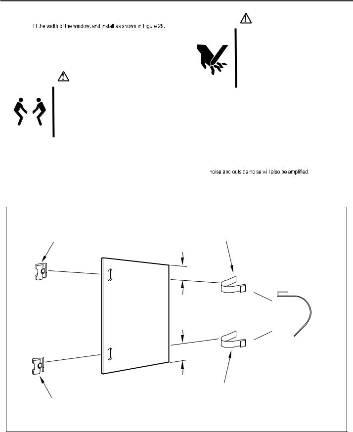
STEP 9. To assemble the wingboard panels, push on the "J" type speed nuts (Item 9) and spring steel clips (Item 10) (See Figures 25) on page 26. Secure each panel with two (2) screws (Item 11).
Figure 16
TOP VIEW OF UNIT
REMOVE AND DISCARD
SCREWS
BACK
LEFT SIDE |
|
RIGHT SIDE |
REMOVE AND DISCARD |
COMPRESSOR |
FAN MOTOR |
|
||
FOAM BLOCKS |
|
|
|
|
EVAPORATOR COIL |
|
|
REMOVE AND SAVE |
|
SCREW FOR |
FRONT |
RE-INSTALLATION |
|
FRR045
21
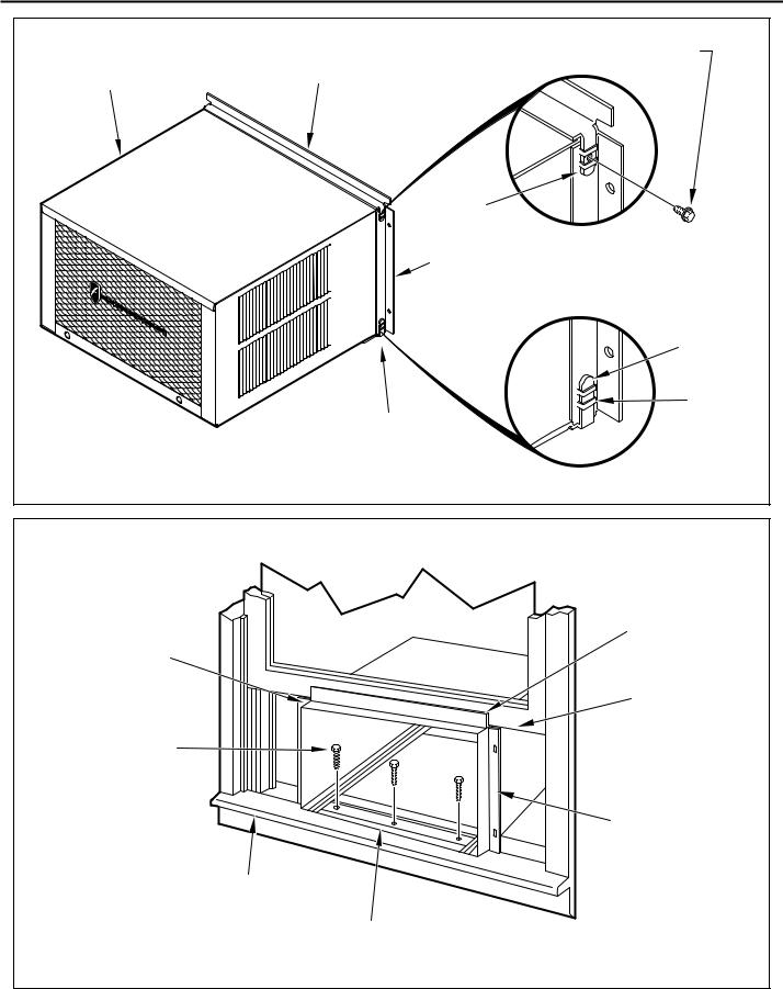
Figure 17 |
|
|
#8 X 3/8” LONG SCREW |
|
(ITEM 7) 2 REQUIRED |
CABINET |
TOP ANGLE (ITEM 5) |
|
|
|
TAB |
|
DETAIL B-2 |
|
SIDE ANGLE |
|
(ITEM 6) |
|
2 REQUIRED |
|
TAB |
|
LOOP |
|
SILL PLATE |
|
TAB |
|
DETAIL B-1 |
|
FRR013 |
Figure 18
TOP ANGLE CENTER (ITEM 5) CABINET
IN WINDOW
SIDE TO SIDE
|
PULL WINDOW |
|
SASH DOWN |
DRILL (3) 5/32” DIA. |
BEHIND TOP |
PILOT HOLES AND |
ANGLE |
INSTALL (3) #12 X 2” |
|
LONG SCREWS |
|
(ITEM 4) |
|
|
SIDE ANGLE |
|
(ITEM 6) |
WINDOW SILL
LOCATE SILL PLATE GUIDE CHANNEL
JUST BACK OF WINDOW SILL
FRR014
22
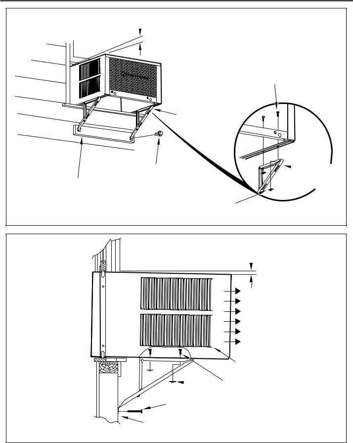
Figure 19
 3/8” SLOPE DOWN
SUPPORT BRACKET (ITEM 1)
#12 X 2” SCREW (ITEM 4)
SPACER SHOULD BE USED BETWEEN
WALL AND BRACKET WHEN INSTALLED ON ALUMINUM OR VINYL SIDING.
10-24 X FLAT WELD NUT (ITEM 3)
#10-24 X 1” HEX HD. SCREW (ITEM 2)
 SUPPORT BRACKET (ITEM 1)
FRR015
Figure 20
 3/8” SLOPE DOWN
CONDENSER
AIR OUTLET
CONDENSER
AIR INLETS
#10-24 SCREW
 #10-24 FLAT WELD NUT
#12 X 2” SHEET METAL SCREW (ITEM 4)
SPACER SHOULD BE USED BETWEEN
WALL AND BRACKET WHEN INSTALLED
ON ALUMINUM OR VINYL SIDING.
FRR016
23
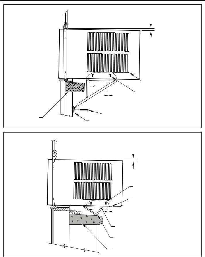
Figure 21
 3/8” SLOPE DOWN
CONDENSER
AIR INLETS
#10-24 SCREW
 #10-24 FLAT WELD NUT
|
#12 X 2” SHEET METAL |
STONE LEDGE |
SCREW (ITEM 4) |
|
SPACER |
FRR017
Figure 22
 3/8” SLOPE DOWN
#10-24 SCREW
STRAIGHTEN TAB TO LAY FLAT
ALONG THE BOTTOM RAIL OF
THE SHELL
 #10-24 FLAT WELD NUT
SECURE THE LONGEST SIDE OF
THE BRACKET TO THE SHELL
ADJUST IN OR OUT TO REST
ON THE LEDGE
STONE LEDGE
FRR018
24
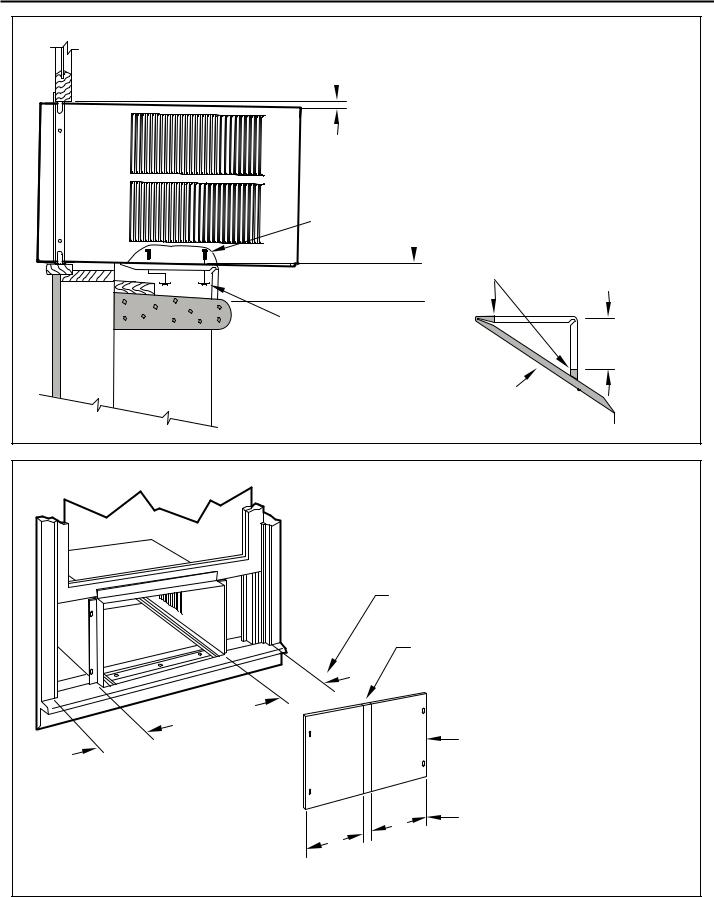
Figure 23
 3/8” SLOPE DOWN
#10-24 SCREW
 DIMENSION “A”
CUT HERE
CUT TO FIT DIMENSION “A” AND BEND DOWN TO FORM A VERTICAL LEG.
#10-24 FLAT WELD NUT 
 STONE LEDGE
 OUTSIDE WALL
  DISCARD SHADED AREA
A
FRR019
Figure 24
MEASURE DISTANCE “B” TO INSIDE OF THE
CHANNEL ON EACH SIDE.
CUT HERE AND DISCARD CENTER WASTE
MATERIAL.
B
B |
WINGBOARD |
|
B |
SUBTRACT 1/8” FROM DIMENSION “B” AND |
|
MEASURE FROM THE EDGE OF THE WING- |
|
|
|
|
B |
|
BOARD (ITEM 8), MARK, SCORE AND CUT |
|
|
WITH APPROPRIATE CUTTING TOOL. |
|
|
FRR020 |
25
STEP 10. INSTALL THE WINDOW SEALING GASKETS – Measure |
|
|
CAUTION |
|||
|
|
and cut the vinyl window seal gasket (grey color, Item 12) to |
|
|
||
|
|
Pull the window sash down behind the gasket. Measure and |
|
|
|
|
|
|
|
|
Cut/Sever |
||
|
|
cut the dark foam window seal gasket (Item 13) and install it |
|
|
||
|
|
|
|
ALTHOUGH GREAT CARE HAS BEEN |
||
|
|
between the upper glass panel and the top part of the lower |
|
|
||
|
|
|
|
TAKEN TO MINIMIZE SHARP EDGES |
||
|
|
window sash (Figure 29). |
|
|
||
|
|
|
|
IN THE CONSTRUCTION OF YOUR UNIT, |
||
|
|
|
|
|
|
USE GLOVES OR OTHER HAND |
|
|
|
|
|
|
PROTECTION WHEN HANDLING UNIT |
|
|
|
|
|
|
|
|
|
|
CAUTION |
|
|
FAILURE TO DO SO CAN RESULT IN MINOR |
|
|
|
|
|
TO MODERATE PERSONAL INJURY. |
|
|
|
|
|
|
|
|
|
|
|
|
|
|
|
|
|
|
Excessive Weight Hazard |
|
|
|
|
|
|
USE TWO OR MORE PEOPLE WHEN |
STEP 11. |
Carefully team lift the chassis and set it into the cabinet. Slide |
|
|
|
|
INSTALLING YOUR AIR CONDITIONER. |
|
|
the chassis stopping approximately 3" from full insertion. Insert |
|
|
|
|
|
the chassis seal gasket (Item 14) one inch deep between the |
|
|
|
|
|
|
|
|
|
|
|
FAILURE TO DO SO CAN RESULT IN |
|
|
chassis and the cabinet (See Figure 29) as shown on page 28. |
|
|
|
|
|
||
|
|
|
BACK OR OTHER INJURY. |
|
|
A paint stir stick or ruler might be helpful here. Begin inserting |
|
|
|
|
|
the gasket at either bottom corner and go up the side, across |
|
|
|
|
|
|
|
|
|
|
|
|
|
|
the top, and down the opposite side. Then push the chassis |
|
|
|
|
|
|
|
|
|
|
|
|
|
all the way into the cabinet. |
|
|
|
|
NOTE: |
If the chassis seal gasket is not installed or installed improperly, |
|
|
|
|
|
|
|
the operation of the unit will be negatively affected. Operational |
|
|
|
|
STEP 12. |
Reattach the entry guard chassis entry guard retainer wire with |
|
|
|
|
|
|
|
the same screw retained in Step 1 (See Figure 14). |
|
|
|
|
|
|
|
|
Figure 25 |
|
|
|
||
|
|
|
|
|
|
SPRING STEEL |
|
|
|
“J” TYPE SPEED NUT |
|
|
CLIP (ITEM 10) |
|
|
|
(ITEM #9) 2 REQUIRED |
|
|
2 REQUIRED |
3"
CUT
WINGBOARD 
 CUT EDGE
PANEL
3" |
ROTATED 90° |
|
CENTER THE HOLE IN THE SPEED NUT OVER THE SLOT IN THE WINGBOARD PANEL
SLIDE CLIP OVER CUT EDGE
OF WINGBOARD PANEL
FRR021
26
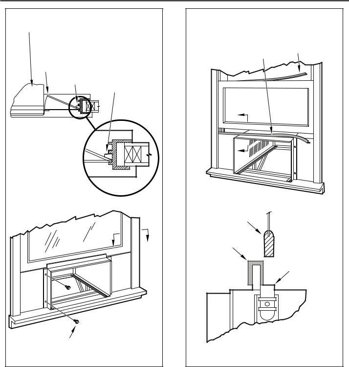
Figure 26
TOP OF CABINET
PLACE WINGBOARD PANEL IN WINDOW JAM
TO COMPRESS THE SPRINGS INSIDE THE
RUNNERS, AND SWING THE WINGBOARD
PANELS INTO PLACE AS INDICATED BY THE
DASHED LINES.
WINDOW JAM
CLIP (ITEM 10)
SECTION A-A
A
A
SECURE THE SIDE WINGBOARD PANELS TO THE SIDE ANGLES WITH FOUR (4) #8 X 1/2” LONG SCREWS (ITEM 11), TWO ON EACH SIDE.
FRR022
Figure 27
INSERT VINYL WINDOW SEAL |
INSERT FOAM WINDOW |
GASKET OVER TOP ANGLE |
SEAL GASKET (ITEM 13) |
TO WINGBOARD (ITEM 12) |
|
B
B
LOWER WINDOW SASH
VINYL
WINDOW
GASKET
TOP WINGBOARD ANGLE
SECTION B-B
FRR023
27
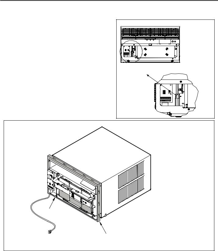
OPTIONAL: The factory assembles the supply cord so that it exits the left side of the unit at the bottom. At the consumer’s discretion, the supply cord can be routed to exit the right side of the unit. To do this, route the supply cord to the right side. Pull the supply cord taunt through the loops (Refer to Cord Routing Change, Figure 30) and route the cord down.
STEP 13. To attach and prevent damage to the front grille align the cord notch over the cord and center the fresh air lever, then align and tighten the four (4) captive screws as indicated by the arrows in Figure 28. Before closing the front panel, be sure the filter is in place. Make sure curtains do not block the side air intakes.
STEP 14. Refer to the Control Panel Operation section for instructions.
STEP 15. You are now ready to control the comfort level of the room.
Use Tool Provided
Please use the provided tool to attach the decorative front to the chassis.
Figure 28 |
USE HAND TOOLS |
DO NOT OVER TIGHTEN |
B |
LOCATION OF GRILLE |
REMOVAL TOOL |
FRR053 |
Figure 29
POWER CORD
CLIP
NOTE: WHEN INSTALLING THE CHASSIS
SEAL GASKET; BEGIN AT EITHER BOTTOM
CORNER AND GO UP THE SIDE & ACROSS
THE TOP & DOWN THE OPPOSITE SIDE.
CHASSIS SEAL
GASKET (ITEM 14)
FRR024
28

THIS PAGE INTENTIONALLY LEFT BLANK
29

Cord Routing Change
UNPLUG UNIT.
 WARNING
Electrical Shock Hazard
MAKE SURE YOUR ELECTRICAL RECEPTACLE HAS THE
SAME CONFIGURATION AS YOUR AIR CONDITIONER’S
PLUG. IF DIFFERENT, CONSULT A LICENSED ELECTRICIAN.
DO NOT USE PLUG ADAPTERS.
DO NOT USE AN EXTENSION CORD.
DO NOT REMOVE GROUND PRONG.
ALWAYS PLUG INTO A GROUNDED 3 PRONG OULET.
FAILURE TO FOLLOW THESE INSTRUCTIONS CAN RESULT IN
DEATH, FIRE, OR ELECTRICAL SHOCK.
For convenience and optimum appearance the direction that the power cord exits the unit may be changed from left to right by following the procedure below. Select the exit location on the left or right based on proximity to the power outlet.
Figure 30
ELECTRICAL
CONTROL PANEL
NOTE:
DECORATIVE FRONT REMOVED USE TOOL PROVIDED. (SEE FIGURE 28 FOR LOCATION OF TOOL).
FRR054
Remove 3 screws as shown from the electrical control panel. Save to reinstall later.
Figure 31 |
ELECTRICAL CONTROL |
PANEL SCREWS (3) |
FRR055 |
30 |
STEP 16. Carefully pull out electrical control panel 1", but not all the way.
Figure 32 |
1 INCH |
FRR056 |
STEP 17. Pull electrical cord strain relief downward until free and rotate 90 degrees to the right.
Figure 33 |
|
90° |
|
ELECTRICAL CORD |
|
STRAIN RELIEF |
FRR057 |
|
STEP 18. Push electrical cord strain relief back upward into the electrical control panel.
Figure 34
ENSURE THE ELECTRICAL CORD STRAIN RELIEF IS FLUSH WITH THE TOP OF ELECTRICAL CONTROL PANEL
FRR058
 Loading...