


2003
Service Ma nual
2003
Room Air Conditioners
RACServMn (7-03)
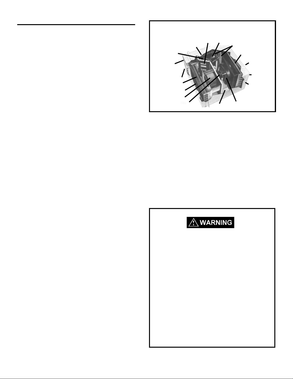
Table of Contents
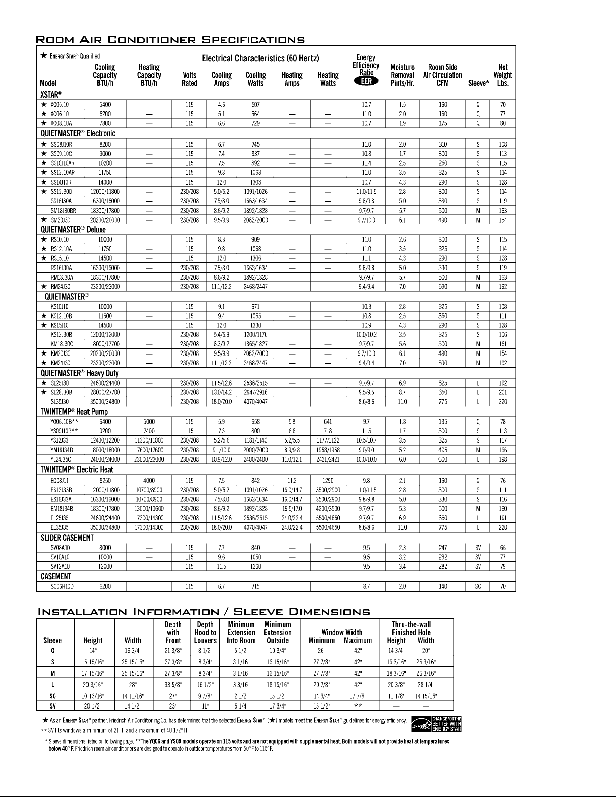
Unit Identification ............................................... 3
Unit Specifications ............................................. 4
Unit Performance ......................................... 5-11
Refrigeration Sequence of Operation ..............12
Electrical Rating Tables ...................................13
Compressor.....................................................14
Thermal Overload (External) ...........................14
Thermal Overload (Internal).............................15
Fan Motor ........................................................ 15
System Switches/Controls ..........................15-24
Thermostats (Indoor)..................................24-25
Thermostats (Defrost) ................................25-26
Resistor (Heat Anticip ator)............................... 26
Capacitor , Run................................................. 26
Check V alve ....................................................27
Heat Pump Reversing V alve............................ 27
Solenoid Coil (Heat Pump Models)..................28
V alve, Drain Pan.............................................. 29
Heating Element .............................................. 29
Sealed Refrigeration Repairs...................... 29-30
Refrigerant Charging ..................................30-31
Undercharged Refrigerant Systems ...........31-32
Overcharged Refrigerant Systems .................. 32
Restricted Refrigerant System.........................33
Routine Maintenance....................................... 34
Troubleshooting.......................................... 34-45
Wiring Diagrams
"RS", "RM",...................................................46
"SQ" ............................................................. 47
"KQ" ........................................................ 48-49
"XQ" ............................................................. 50
"YQ" ............................................................. 51
"SC" ............................................................. 52
"SS", "SM" .................................................... 53
"SL" ..............................................................54
"KS", "KM", "KL" ...........................................55
"ES", "EM", "EL", "EK" .................................. 56
"YS13", "YM", "YL" ....................................... 57
"YS09"..........................................................58
"EQ" ............................................................. 59
"WS".............................................................60
"WE".............................................................61
"WY"............................................................. 62
Testing XQ and QME Boards .......................... 63
Typical Unit Components
Capillary Tube
Reversing Valve
(some models)
Front Cover
System Switches
Evaporator Coil
Return Air Grille/Filter
Blower Wheel
Blower Motor
Fresh Air
Compressor
Basepan
Liquid Filter Driers
Condenser Coil
Discharge Air
Outdoor Grille
Sleeve
Condenser Fan Blade
Introduction
This service manual is designed to be used in conjunction
with the installation manuals provided with each air
conditioning system component.
This service manual was written to assist the professional
RAC service technician to quickly and accurately diagnose
and repair malfunctions.
This manual will deal with subjects in a general nature.
(i.e. all text will not pertain to all models).
IMPORTANT: It will be necessary for you to accurately
identify the unit you are servicing, so you can be certain of
a proper diagnosis and repair. (See Unit Identification.)
The information contained in this manual is intended
for use by a qualified service technician who is
familiar with the safety procedures required in
installation and repair , and who is equipped with the
proper tools and test instruments.
Installation or repairs made by unqualified persons
can result in hazards subjecting the unqualified
person making such repairs to the risk of injury or
electrical shock which can be serious or even fatal
not only to them, but also to persons being served
by the equipment.
If you install or perform service on equipment, you
must assume responsibility for any bodily injury or
property damage which may result to you or others.
Friedrich Air Conditioning Company will not be
responsible for any injury or property damage arising
from improper installation, service, and/or service
procedures.
2
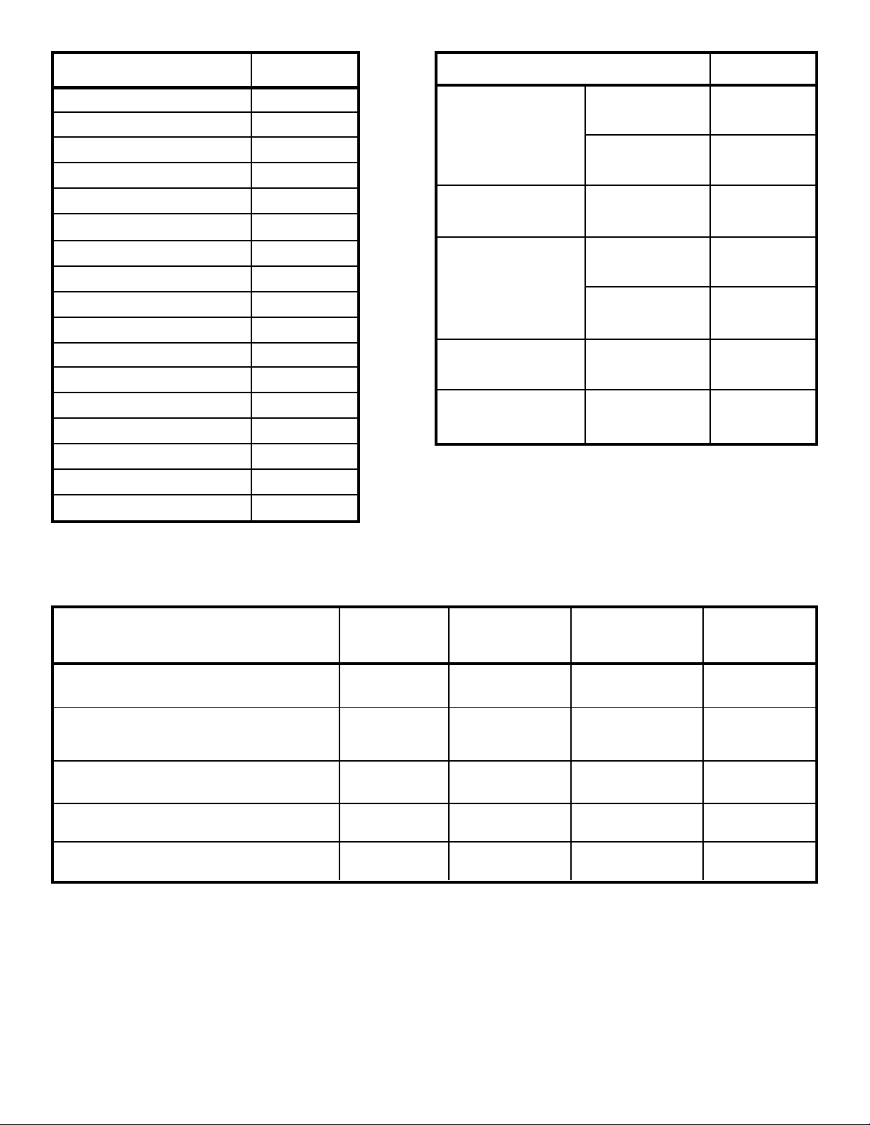
UNIT IDENTIFICAUNIT IDENTIFICA
UNIT IDENTIFICA
UNIT IDENTIFICAUNIT IDENTIFICA
Model Number Code
SS08J 1 0 R
TIONTION
TION
TIONTION
1st Digit – Function
S = Straight Cool, Value Series
C = Straight Cool, Budget
Series
Y = Heat Pump
E = Electric Heat
K = Straight Cool, Challenger
Series
W = Thru-the Wall,
WallMaster Series
2nd Digit
C = Casement
P = PowerMiser "Portable"
Q = Q-Star
M = Medium Chassis
L = Large Chassis
W = Built -In
H = HazardGard
8th Digit – Engineering
Major change
7th Digit – Options
0 = Straight Cool & Heat Pump Models
1 = 1 KW Heat Strip, Normal
3 = 3 KW Heat Strip, Normal
4 = 4 KW Heat Strip, Normal
5 = 5 KW Heat Strip, Normal
8 = 8 KW Heat Strip, Normal
6th Digit – Voltage
1 = 115 Volts
2 = 230 Volt s
3 = 230-208 Volt s
5th Digit
Alphabetical Modifier
3rd and 4th Digit Approximate BTU/HR
(Cooling)
Heating BTU/Hr capacity listed in
the Specification/Performance
Data Section
RAC Serial Number Identification Guide
Serial Number
Decade Manufactured
L=0 C=3 F=6 J=9
A=1 D=4 G=7
B=2 E=5 H = 8
Year Manufactured
A=1 D=4 G=7 K=0
B=2 E=5 H = 8
C=3 F=6 J=9
Month Manufactured
A=Jan D=Apr G=Jul K=Oct
B=Feb E=May H=Aug L=Nov
C=Mar F=Jun J=Sep M=Dec
L C G S 00001
Production Run Number
PRODUCT LINE
S=RAC
P=PTAC
E=EAC
V=VPAK
H=Split
3
4
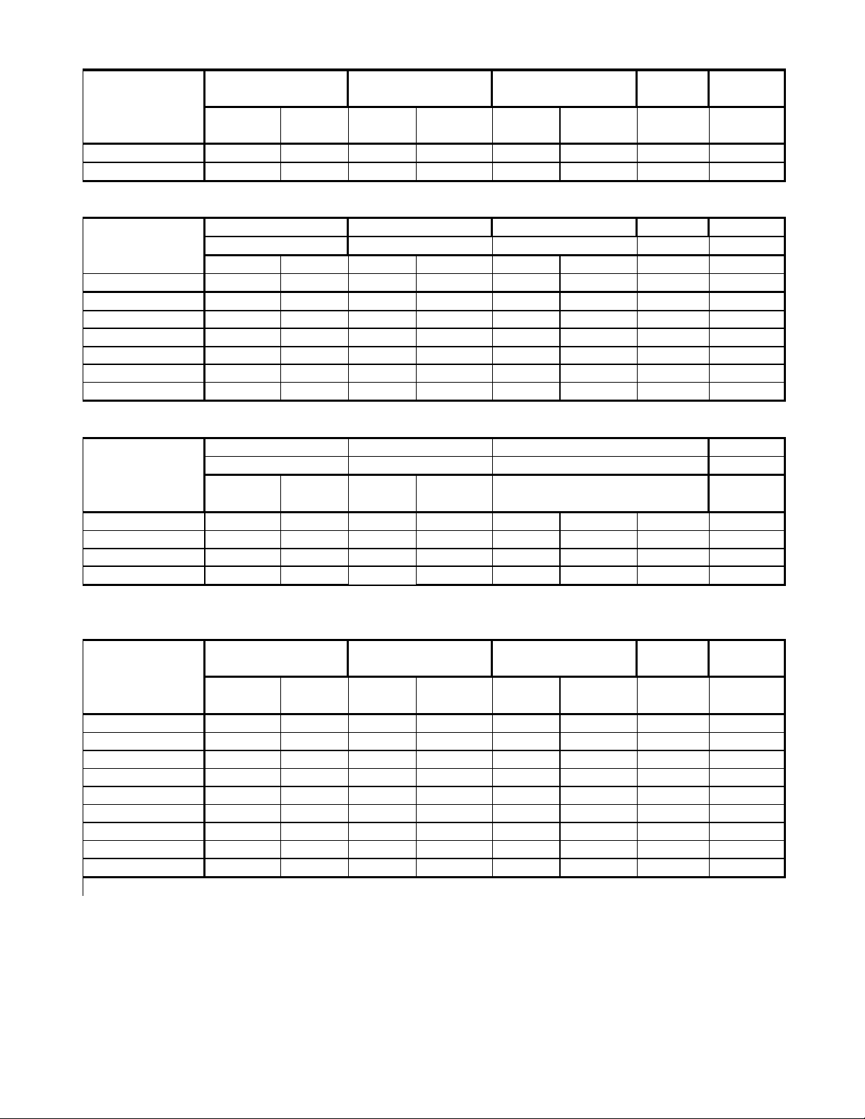
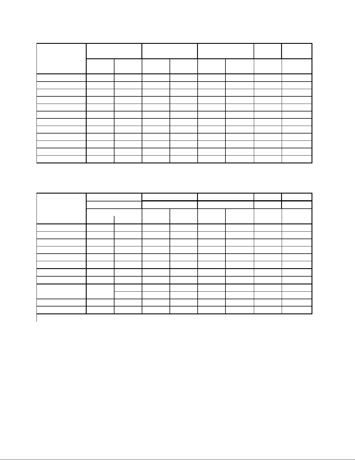
EQ PERF O RMANCE DATA
PERFORMANCE R-22 BREAKER
DATA* REFRIG. FUSE
EVAPORATOR AIR
TEMP. DEG. F.
OPERATING
PRESSURES
ELECTRICAL
RATINGS
Cooli ng Dis charge Temp. Suct i on Dis charge Am p s Loc ked Charge in 60 Hertz
Air Drop F. Rotar Amp OZ. Amps
EQ08J11-A 50.5 29.5 72 262 7.5 39.2 20 15
EQ08J11-B 50.5 29.5 74 259 7.5 39.2 20 15
XQ PERF O RMANCE DATA
DATA* R-22 BREAKER
Cooling REFRIG. FUSE
EVAPORATOR AIR OPERATING ELECTRICAL
TEMP. DEG. F. PRESSURES RATINGS
Dis charge Temp. Suct i on Dis charge Am p s Loc ked Charge in 60 Hertz
Air Drop F. Rotar Amp OZ. Amps
XQ05J10B 55.45 24.55 79 245 4.6 34 20 15
XQ06J10-A 51.45 28.55 82 262 5.1 35 21 15
XQ06J10-B 51.45 28.55 79 254 5.1 35 21 15
XQ07J10-1 52.22 27.95 77 250 6.5 37 24 15
XQ08J10-1 50.5 29.5 72 262 4.5 38 20 15
XQ08J10-A 50.5 29.5 72 262 4.5 38 21 15
SQ PERF O RMANCE DATA
PERFORMANCE EVAPORATOR AIR ELECTRICAL R-22 BREAKER
DATA * TEMP. DEG. F. RATINGS REFRIG. F USE
OPERATING
PRESSURES
Cooli ng Dis charge Temp. Suct i on Dis charge Am p s Loc ked Charge in 60 Hertz
Air Drop F. Rotar Amp OZ. Amps
SQ05J10B-B 55.45 24.55 79 245 4.4 34.'0 16.'0 15
SQ06J10B-A 51.45 28.55 82 262 5.2 35.'0 15.7 15
SQ06J10B-B 51.45 28.55 79 254 5.2 35.'0 15.7 15
SQ08J10C-1 50.5 29.5 72 262 7.5 39.2 19.5 15
KQ-YQ PERFORMANCE DATA
PERFORMANCE R-22 BREAKER
DATA* REFRIG. FUSE
EVAPORATOR AIR OPERATING
TEMP. DEG. F. PRESSURES RATINGS
ELECTRICAL
Cooli ng Dis charge Temp. Suct i on Dis charge Am p s Loc ked Charge in 60 Hertz
Air Drop F. Rotar Amp OZ. Amps
KQ05J10B-B 56.34 28.66 73 251 5.2 29.'0 15.'0 15
KQ05E10-B 56.34 28.66 79 245 5.2 29.'0 15.'0 15
KQ05E10-C 56.34 28.66 79 245 5.2 29.'0 15.'0 15
KQ06J10B-A 58.02 21.98 82 262 5.8 35.'0 15.'0 15
KQ06J10B-B 58.02 21.98 80 269 5.8 35.'0 19.'0 15
KQ06E10-A 58.02 21.98 82 262 5.8 35.'0 15.'0 15
KQ06E10-B 58.02 21.98 79 254 5.8 35.'0 15.'0 15
YQ06J10B-A 54.1 25.9 81 267 5.7 39.2 19.'0 15
*Rating Condit i ons : 80 degree F. Room Ai r Temperature and 50% Relat ive Humidity with
95 degree F. Outside Ai r Temperature and 40% Relat ive Humitidy
5
R
R
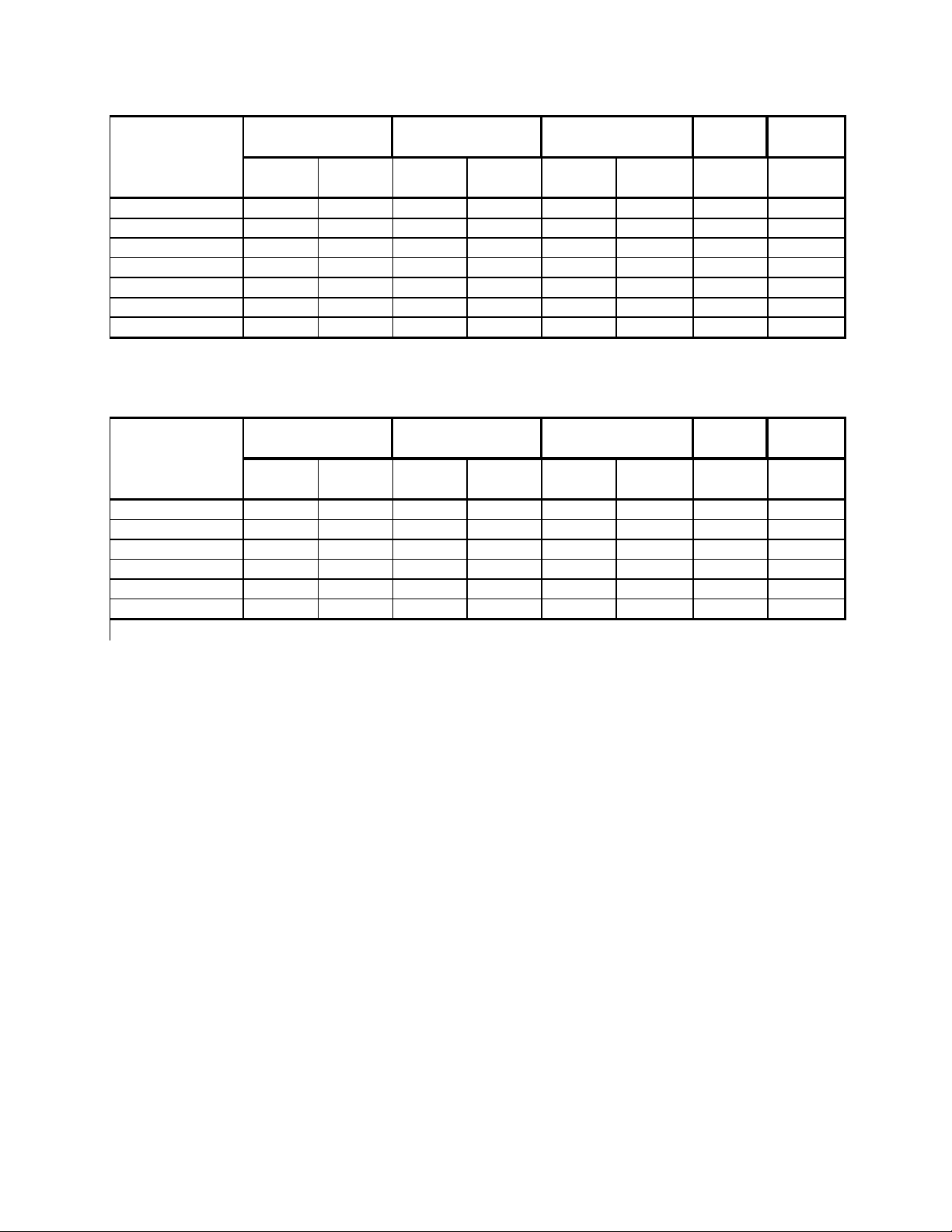
RS-RM PERFORMANCE DA TA
PERFORMANCE R-22 BREAKE
DATA* REFRIG. FUSE
EVAPORATOR AIR
TEMP. DEG. F.
OPERATING
PRESSURES
ELECTRICAL
RATINGS
Cooling Dis c harge Temp. Suct i on Discharge Amps Lock ed Charge in 60 Hert z
Ai r Drop F. Rotar Amp OZ. Am p s
RS10J10-C 61 19 82 248 7.5 44 26 15
RS12J10A-B 57 23 83 271 9.8 54 30 15
RS15J10-A 57 23 77 279 11.1 42 29.5 15
RS16J30A-A 56.5 24 77 296 7.2 42 30 15
RS18J30-A 56 24 72 293 8.7 42 48 15
RM24J30-A 57 23.65 68 301 12.2 44 54 15
YS-YM-YL PERFORMANCE DATA
PERFORMANCE R-22 BREAKE
DATA* REFRIG. FUSE
EVAPORATOR AIR OPERATING ELECTRICAL
TEMP. DEG. F. PRESSURES RATINGS
Cooling Dis c harge Temp. Suct i on Di scharge Amps Locked Charge in 60 Hert z
Ai r Drop F. Rotar Amp OZ. Am p s
YS09J10 B-A 59 21 90 243 7.7 39.2 25 15
YS12J33 - A 56 24 80 264 5.2/5.6 30 28 20
YM18J34B-A 53 27 74 284 8.7/9.2 42 54 30
YL24J35C-A 55 25 72 260 10.0/12.0 61 74 30
* Rating Condit i ons : 80 degree F. Room Ai r Temperature and 50% Relati ve Hum i dity wit h
95 degree F. Outside Ai r Temperature at 40% Relat i ve Hum idi t y.
6
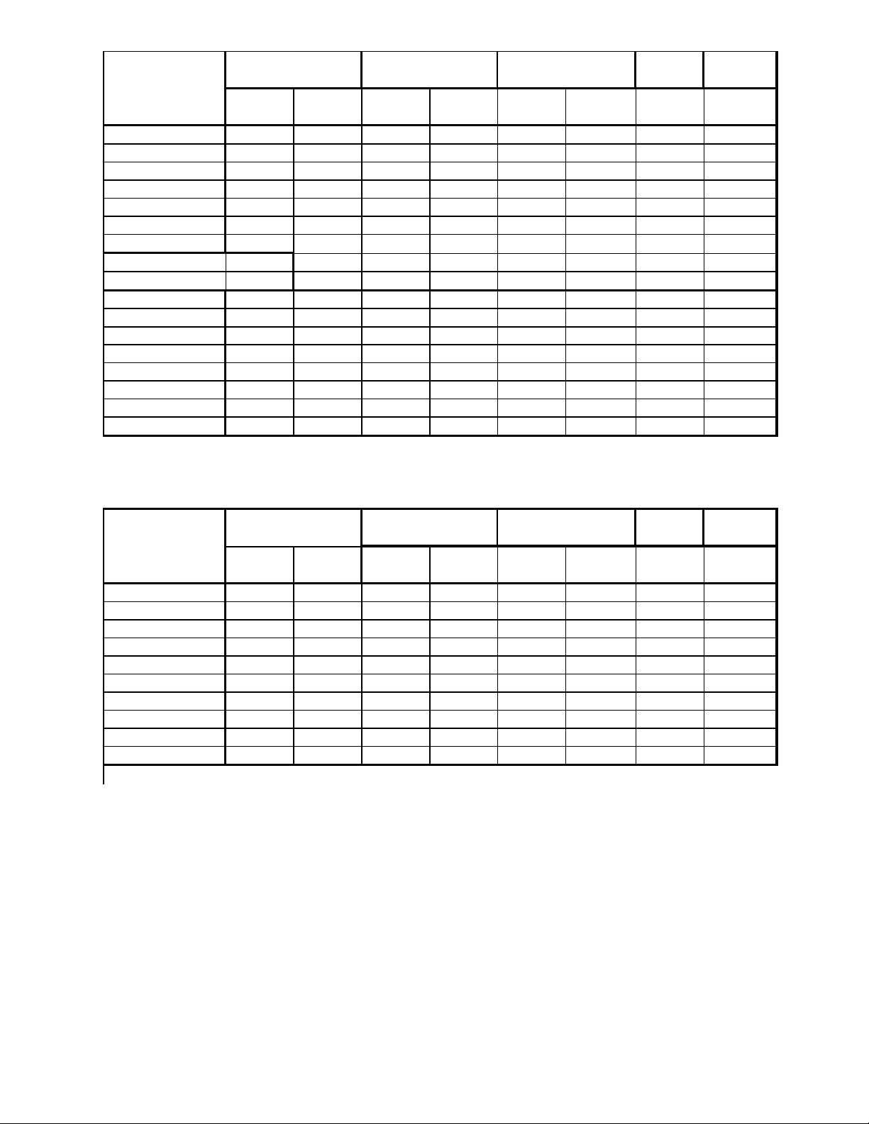
PERFORMANCE R-22 BREAKE
R
DATA* REFRIG. FUSE
EVAPORATOR AIR
TEMP. DEG. F.
OPERATING
PRESSURES
ELECTRICAL
RATINGS
Cooling Dis c harge Temp. S ucti on Discharge A m ps Locked Charge in 60 Hertz
Air Drop F. Rotar Amp OZ. Amps
ES12J33B-A 58 22 82 265 5.76.6 26.3 28 20
ES16J33 A-A 53 27 77 269 7.5/8.0 42.'0 30 20
EM18J34B-A 55 25 71 267 8.6/9.2 42.'0 40.5 30
EL25J35-A 55 25 75 284 11.5/12.6 61.'0 48.5 30
EL35J35-A 52 28 72 317 18/20 94.'0 60 30
EL35J35-B 52 28 72 317 18/20 94.'0 60 30
PERFORMANCE H ea t Ris e
DATA heating
ES12J33 B-A 30.5 16/14.7
ES16J33 A-A 30.5 16/14.7
EM18J34B-A 28.3 19.5/17
EL25J35-A 28.6 24/22/4
EL35J35-A 22.9 24/22.4
EL35J35-B 22.9 24/22.4
KS-KM PERFORMANCE DATA
DATA* R-22 BREAKER
Cooling REFRIG. FUSE
EVAPORATOR AIR OPERATING ELECTRICAL
TEMP. DEG. F. PRESSURES RATINGS
Discharge Temp Amps Lock ed Charge in 60 Herts
Air Drop F. Rotar Amp OZ. Amps
KS10E10-A 61 19 82 248 9.1 48.3 2 6.08 15
KS10J10 - B 61 19 80 263 9.1 48.3 2 6.88 15
KS12E10-A 57 23 83 271 10.8 54.'0 28 15
KS12J10 B-A 57 23 84 268 10.8 54.'0 28 15
KS15J10 - A 55.78 23.52 77 279 12.'0 67.'0 29.5 15
KS12J30 B-A 57 23 76 285 6.2 26.'0 30.08 15
KS18J30 - A 56 24 72 293 8.7 48 4 8 15
KM20J30-A 55 24 70 279 9.9 48 48 15
KM24J30-A 55 25 68 301 15.'0 71.'0 54.08 15
* Rating Condit i ons : 80 degree F. Room Air Temperature and 50% Relative Humidity with
95 degree F. Out s i de A i r Temperature at 40% Relat i ve Hum i dit y.
7
R
R
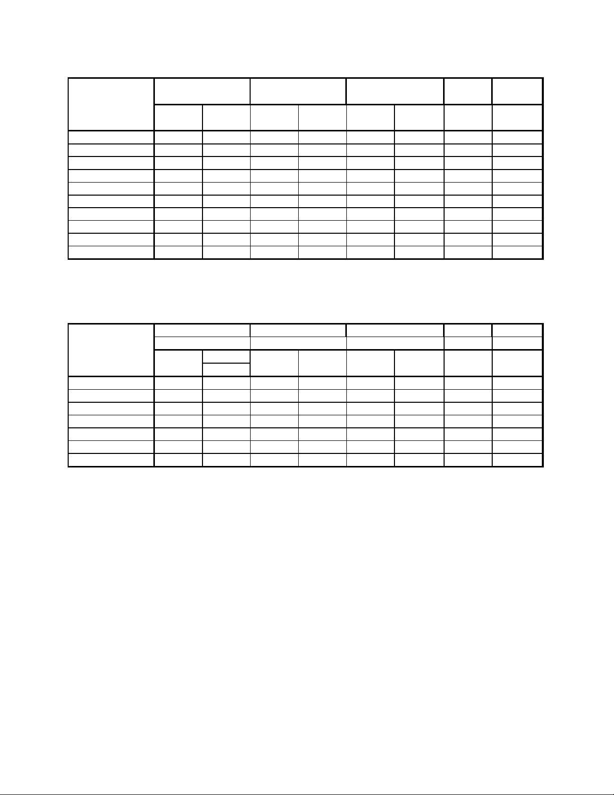
SS PERFORMANCE DATA
PERFORMANCE R-22 BREAKE
DATA* REFRIG. FUSE
EVAPORATOR AIR
TEMP. DEG. F.
OPERATING
PRESSURES
ELECTRICAL
RATINGS
Cooling Dis c harge Temp. S uction Dis charge A mps Lock ed Charge in 60 Hertz
Air Drop F. Rotar Amp OZ. Amps
SS08J1 0R-B 61.4 1 8.6 87 251 6.7 29 39.'0 15
SS08J1 0R-A 61.4 1 8.6 84 248 6.7 36.2 24.'0 15
SS09J1 0C-A 57.8 2 2.2 82 254 7.4 44 22.6 15
SS10J10AR-A 57.22 22.78 84 245 7.5 42 26.'0 15
SS12J1 0AR-B 57.2 22.8 83 271 9.8 44 30.'0 15
SS14J10R-A 57.22 22.9 77 279 12 61 29.5 15
SS12J3 0D-A 57.2 22.8 82 265 5.0/5.2 21 27.5 20
SS16J3 0A-A 56.9 23 77 296 7.5/8.0 2 8 30.'0 20
SS18J3 0R-A 56.9 23 77 293 8.1/8.7 45 48 20
SM-SL PE RF ORMANCE DA TA
PERFORMANCE R-22 BREAKE
DATA* REFRIG. FUSE
EVAPORATOR AIR OPERATING ELECTRICAL
TEMP. DEG. F PRE SS URES RATINGS
Cooling Dis c harge Temp Suction Dis charge A mps Lock ed Charge in 60 Hertz
Air Drop F. Rotar Amp OZ. Amps
SM20J30-A 52.58 27.42 70 279 9.9 43 47 20
SM24J30-A 54.86 25.14 68 301 12.2 68 54 20
SL25J30-A 52.32 27.68 75 284 11.5/12.6 68 48.5 20
SL28J30B-A 52.1 26.9 74 278 13.0/14.2 88 50 20
SL35J30-A 52.93 27.07 72 317 18.0/20.0 92 60 30
SL35J30-B 52.93 27.07 72 317 18.0/20.0 92 60 30
* Rating Condit ions: 80 degree F. Room A i r Temperature and 50% Relati ve Humi di t y with
95 degree F. Out s i de A i r Temperature at 40% Rel at i ve Humi dity.
8
WS PERFORMANCE DATA
PERFORMANCE R-22 BREAKER
DATA* REFRIG. FUSE
EVAPORATOR AIR
TEMP. DEG. F.
OPERATING
PRESSURES
ELECTRICAL
RATINGS
Cooling Dis c harge Temp. S ucti on Di scharge Amps Locked Charge in 60 Hertz
Air Drop F. Rotar Amp OZ. Amps
WS07A10E-B 59.5 19.5 84 300 7.'0 32 19 15
WS07A10E-C 59.5 19.5 85 299 7.'0 32 28 15
WS07A10E-D 59.5 19.5 85 299 7.'0 32 20 15
WS10A10-A 58 22 83 307 9.8 48 25 15
WS10A10-B 58 22 83 307 9.8 48 26 15
WS12A10E-B 55 25 81 290 11.9 54 28.5 15
WS13A10-A 55 25 79 281 12 55 36 15
WS09A30E-B 58 22 86 302 4.7 44 22 15
WS12A30E-A 47.1 32.9 80 308 11.9 54 27.5 15
WS12A30E-B 46 33 80 305 11.9 54 42 15
WS15A30-A 47 33 72 310 8.5 42 43.5 15
W E-WY PERF O RM ANCE DATA
DATA* R-22 BREAKER
Cooling REFRIG. FUSE
EVAPORATOR OPERATION ELECTRICAL
TEMP. DEG. F. P RESSURES RATINGS
Discharge Temp. Suct i on Discharge A m ps Locked Charge in 60 Hertz
Air Drop F. Rotar Amp OZ. Amps
WE09A33E-C 58 22 86 302 4.7 44 23 20
WE12A33E-B 55 25 80 308 6.5 54 27.5 20
WE15A33-A 47.1 32.9 71 310 8.5 42 43.5 20
WY09A33F-A 58 22 83 288 4.3 44 24 20
WY12A33G-A 55 25 81 295 6.2 54 37 20
PERFORMANCE H ea t Rise
DATA heating
WE15A33-A 40 16.2
WE09A33E-C 39 14.7
WE12A33E-B 36 14.7
* Rating Condit ions: 80 degree F. Room A i r Temperature and 50% Relat ive Hum i dity
95 degree F. Out s i de A i r Temperature at 40% Relat i ve Hum idi t y
9
SPECIFICATIONS SC06H10E
BTUH (Cooling) 5950
E.E.R. (Cooling) 8.0
Volts 115
Amperes (Cooling) 6.8
Total Watts (Cooling) 760
Hertz 60
Fuse/Breaker Size 15
Fan RPM 1595
Evaporator Air CFM 125
Dehumidification Pts/Hr 2.0
Width 141 1/16"
Height 1013/16"
Depth 27"
Minimum Ext. Into Room 2½"
PERFORMANCE DA T A* SC06H10E
DISCHARGE 56.1
EVAPORA TOR AIR AIR
TEMP. °F TEMP 23.9
DROP °F
OPERATING SUCTION 72
PRESSURES DISCHARGE 293
AMPS 6.8
ELECTRICAL
RA TINGS LOCKED 35.0
ROTOR AMPS
R-22 CHARGE IN 14
REFRIG. OUNCES
COMP. CHARGE IN 9.8
OIL FLUID OZ.
Minimum Ext. To Outside 15½"
Net Weight 70
* Rating Conditions:
80°F Room Air Temperature and 50% Relative Humidity with
95°F Outside Air Temperature at 40% Relative Humidity .
Shipping Weight 80
PERFORMANCE DA T A *YS09J10B-A **YS12J33-A **YM18J34A-A **YL24J35C-A
(Heating)
AHAM @ 70°F Inside 47°F Outside 8300 12400/12300 17200/17200 23000/22800
@ 70°F Inside 35°F Outside 10700/8900 13000/10600 17300/14300
Evaporator Air Temperature Rise
@ 70°F Inside 47°F Outside 19.62 31.38 24.74 31.71
@ 70°F Inside 35°F Outside 28.69/23.87 24.46/20.22 24.38/20.16
AMPS @ 70°F Inside 47°F Outside 6.7 6.0/6.5 8.5/9.0 10.4/11.5
@ 70°F Inside 35°F Outside 16.0/14.7 19.5/17.0 24.0/22.4
Watts @ 70°F Inside 47°F Outside 760 1340/1300 1880/1820 2350/2340
@ 70°F Inside 35°F Outside 3500/2900 5500/4650 5500/4650
Suction/Head PSIG
@ 70°F Inside 47°F Outside 53.5/222 52.5/251 53/225 54/236.5
* Do not operate below 37° ambient.
** Heating element comes on at 35°F outside ambient and compressor shuts off.
10
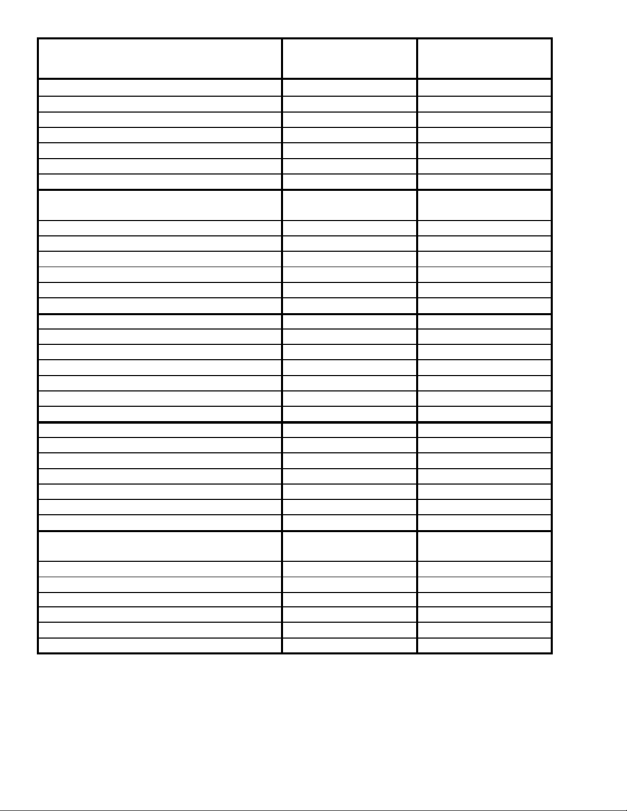
PERFORMANCE DA T A *WY09A33F-A *WY12A33F-A
(Heating)
BTUH @70°F Inside 62°F Outside 9700 12400
@70°F Inside 57°F Outside 9300 12000
@70°F Inside 52°F Outside 8800 11400
** @70°F Inside 47°F Outside 8200/8100 10800/10400
@70°F Inside 42°F Outside 7600 10000
@70°F Inside 37°F Outside 6800 9000
@70°F Inside 35°F Outside 1 1000/9100 11000/9100
Evaporator Air Temperature Rise
@70°F Inside 62°F Outside 32.00 37.60
@70°F Inside 57°F Outside 30.75 36.40
@70°F Inside 52°F Outside 29.10 34.50
** @70°F Inside 47°F Outside 27.10/26.80 32.70/31.50
@70°F Inside 42°F Outside 25.10 30.30
@70°F Inside 37°F Outside 22.50 27.30
@70°F Inside 35°F Outside 36.40/30.10 33.30/27.60
AMPS @70°F Inside 62°F Outside 4.0 5.6
@70°F Inside 57°F Outside 3.9 5.5
@70°F Inside 52°F Outside 3.85 5.4
** @70°F Inside 47°F Outside 3.8/4.1 5.3/5.6
@70°F Inside 42°F Outside 3.6 5.1
@70°F Inside 37°F Outside 3.4 4.8
@70°F Inside 35°F Outside 16.0/14.7 16.0/14.7
Watt s @70°F Inside 62°F Outside 880 1280
@70°F Inside 57°F Outside 870 1260
@70°F Inside 52°F Outside 860 1220
** @70°F Inside 47°F Outside 835/810 1175/1155
@70°F Inside 42°F Outside 800 1 1 30
@70°F Inside 37°F Outside 760 1070
@70°F Inside 35°F Outside 3550/2950 3550/2950
Suction/Head PSIG
@70°F Inside 62°F Outside 66/315 61/325
@70°F Inside 57°F Outside 62/285 59/290
@70°F Inside 52°F Outside 57/285 53/275
** @70°F Inside 47°F Outside 53/265 49/255
@70°F Inside 42°F Outside 49/215 45/240
@70°F Inside 37°F Outside 45/203 41/220
@70°F Inside 35°F Outside 44/200 40/215
* Heating Element comes on at 35°F outside ambient and compressor shuts off.
** AHAM Rating Conditions.
11
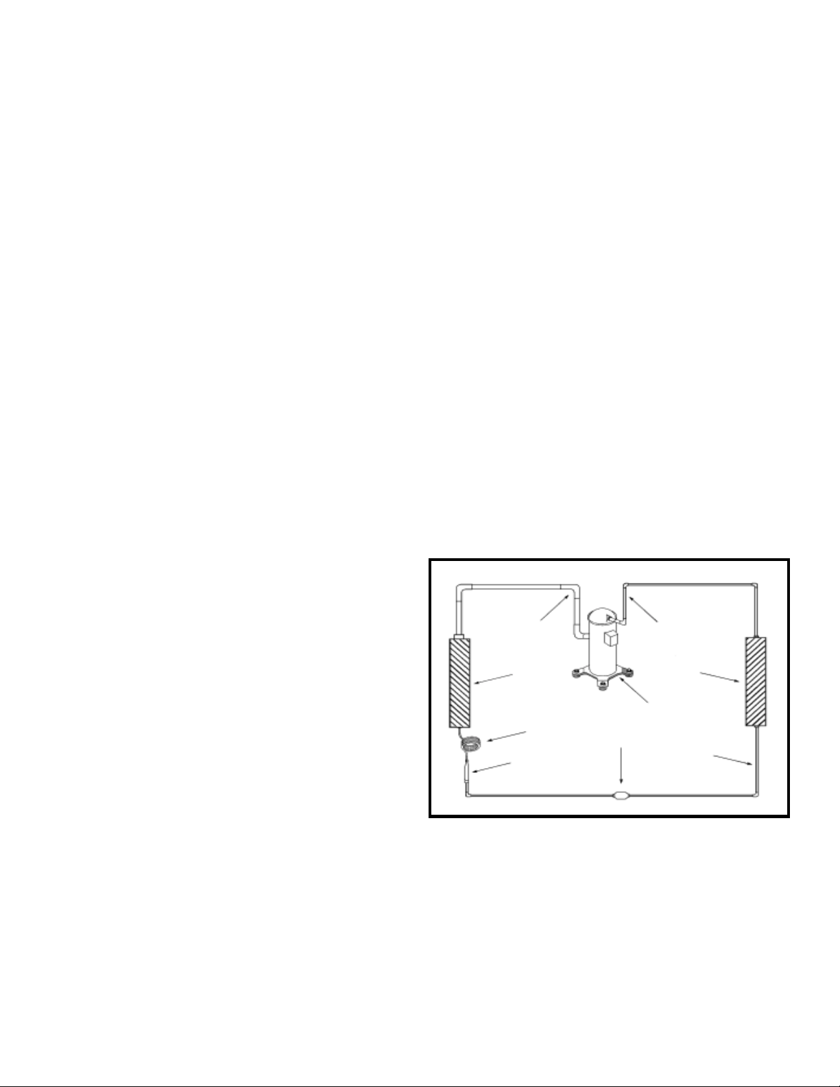
Refrigeration SystemRefrigeration System
Refrigeration System
Refrigeration SystemRefrigeration System
Sequence of OperationSequence of Operation
Sequence of Operation
Sequence of OperationSequence of Operation
A good understanding of the basic operation of the refrigeration
system is essential for the service technician. Without this
understanding, accurate troubleshooting of refrigeration
system problems will be more difficult and time consuming, if
not (in some cases) entirely impossible. The refrigeration
system uses four basic principles (laws) in its operation they
are as follows:
1. "Heat always flows from a warmer body to a cooler body."
2. "Heat must be added to or removed from a substance
before a change in state can occur"
3. "Flow is always from a higher pressure area to a lower
pressure area."
4. "The temperature at which a liquid or gas changes state
is dependent upon the pressure."
The refrigeration cycle begins at the compressor. Starting
the compressor creates a low pressure in the suction line which
draws refrigerant gas (vapor) into the compressor. The
compressor then "compresses" this refrigerant, raising its
pressure and its (heat intensity) Temperature.
The refrigerant leaves the compressor through the discharge
line as a hot high pressure gas (vapor). The refrigerant enters
the condenser coil where it gives up some of its heat. The
condenser fan moving air across the coil's finned surface
facilitates the transfer of heat from the refrigerant to the
relatively cooler outdoor air.
In the case of the capillary tube this is accomplished (by design)
through size (and length) of device, and the pressure difference
present across the device.
Since the evaporator coil is under a lower pressure (due to the
suction created by the compressor) than the liquid line, the liquid
refrigerant leaves the metering device entering the evaporator coil.
As it enters the evaporator coil, the larger area and lower pressure
allows the refrigerant to expand and lower its temperature (heat
intensity). This expansion is often referred to as "boiling". Since
the unit's blower is moving Indoor air across the finned surface of
the evaporator coil, the expanding refrigerant absorbs some of
that heat. This results in a lowering of the indoor air temperature,
hence the "cooling" effect.
The expansion and absorbing of heat cause the liquid refrigerant
to evaporate (i.e. change to a g as). Once the refrigerant has
been evaporated (changed to a gas), it is heated even further by
the air that continues to flow across the evaporator coil.
The particular system design determines at exactly what point (in
the evaporator) the change of state (i.e. liquid to a gas) takes
place. In all cases, however, the refrigerant must be totally
evaporated (changed) to a gas before leaving the evaporator coil.
The low pressure (suction) created by the compressor causes the
refrigerant to leave the evaporator through the suction line as a
cool low pressure vapor. The refrigerant then returns to the
compressor, where the cycle is repeated.
When a sufficient quantity of heat has been removed from
the refrigerant gas (vapor), the refrigerant will "condense" (i.e.
change to a liquid). Once the refrigerant has been condensed
(changed) to a liquid it is cooled even further by the air that
continues to flow across the condenser coil.
The RAC design determines at exactly what point (in the
condenser) the change of state (i.e. gas to a liquid) takes place.
In all cases, however, the refrigerant must be tot ally condensed
(changed) to a liquid before leaving the condenser coil.
The refrigerant leaves the condenser coil through the liquid line
as a warm high pressure l iquid. It next will pass through the
refrigerant drier (if so equipped). It is the function of the drier to
trap any moisture present in the system, contaminants, and large
particulate matter.
The liquid refrigerant next enters the metering device. The metering
device is a capillary tube. The purpose of the metering device is to
"meter" (i.e. control or measure) the quantity of refrigerant entering
the evaporator coil.
Suction
Line
Evaporator
Coil
Metering
Device
Refrigerant
Dryer
Discharge
Line
Condenser
Coil
Compressor
Refrigerant
Drier
Liquid
Line
12
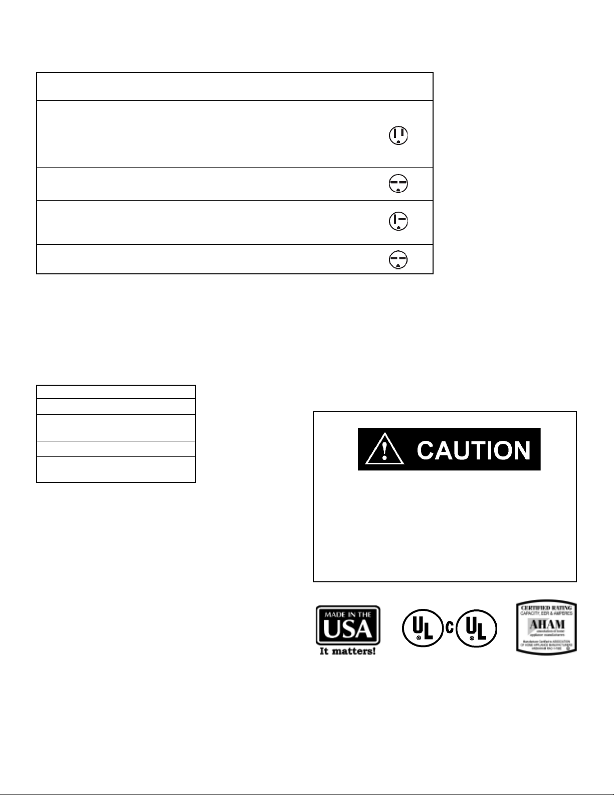
Electrical Rating TElectrical Rating T
Electrical Rating T
Electrical Rating TElectrical Rating T
Circuit Rating Plug Face Appearance
Model Breaker or T-D Fuse (NEMA#) (Facing Blades)
ALL SV and XQ MODELS,
KS10J10, KS12J10B, KS15J10, RS10J10, RS12J10A,
RS15J10, SS08J10R, SS09J10C, SS10J10AR,
SS12J10AR, SS14J10R, SC06H10D,
EQ08J11, YQ06J10B, YS09J10B
125V - 15A 5 - 15P
ablesables
ables
ablesables
KS12J30B, KM18J30C, RS16J30A,
RM18J30A, SS12J30D, SS16J30A, SM18J30BR
KM20J30, KM24J30, SM20J30,
SL25J30, SL28J30B*, ES12J33B, 250V - 20A
ES16J33A, YS12J33
SL35J30, EM18J34B, EL25J35, EL35J35,
YM18J34B, YL24J35C
*
Optional 30 Amp Kit (618-869-00) is recommended in 208 Volt power supply areas that fall below 208 Volts.
For more information, call the Friedrich Service Department.
Due to a program of continuing improvement, specifications are subject to change without notice.
250V - 15A
250V - 30A 6 - 30P
6 - 15P
6 - 20P
Installation Notes:
Supply Cord - All with right angle plug 6' on 115V; 5' on 230/208V.
Room air conditioners include accessories for window or thru-the-wall installation.
TWINTEMP
Window mounting requires use of optional accessory kit as listed below:
MODEL KIT NO.
EQ08J11, YQ06J10B WIKQ
ES12J33B, ES16J33A, WIKS
YS09J10B, YS12J33
EM18J34B, YM18J34B WIKM
EL25J35, EL35J35, WIKL
YL24J35C
®
models include accessories for thru-the-wall installation only.
Turn off electric power before service or installation.
Electric shock hazard.
Wire Size Use ONLY wiring size recommended for
single outlet branch circuit.
Fuse/Circuit Use ONLY type and size fuse or HACR
Breaker circuit breaker indicated on unit's rating
plate. Proper current protection to the unit
is the responsibility of the owner.
Grounding Unit MUST be grounded from branch circuit
through service cord to unit, or through
separate ground wire provided on permanently
connected units. Be sure that branch circuit
or general purpose outlet is grounded.
Receptacle The field supplied outlet must match plug on
service cord and be within reach of service
cord.
Do NOT alter the service cord or plug. Do
NOT use an extension cord. Refer to the table
above for proper receptacle and fuse type.
All electrical connections and wiring MUST be installed by a qualified
electrician and conform to the National Electrical Code and all local
codes which have jurisdiction.
Failure to do so can result in property damage, personal injury and/
or death.
The consumer - through the AHAM Room Air Conditioner
Certification Program - can be certain that the AHAM
Certification Seal accurately states the unit's cooling and
heating capacity rating, the amperes and the energy efficiency
ratio.
13
COMPONENTS:
OPERATION & TESTING
WARNING
DISCONNECT ELECTRICAL POWER TO
UNIT BEFORE SERVICING OR TESTING
COMPRESSORS
Compressors are single phase, 115 or 230/208 volt,
depending on the model unit. All compressor motors are
permanent split capacitor type using only a running capacitor
across the start and run terminal.
All compressors are internally spring mounted and externally
mounted on rubber isolators.
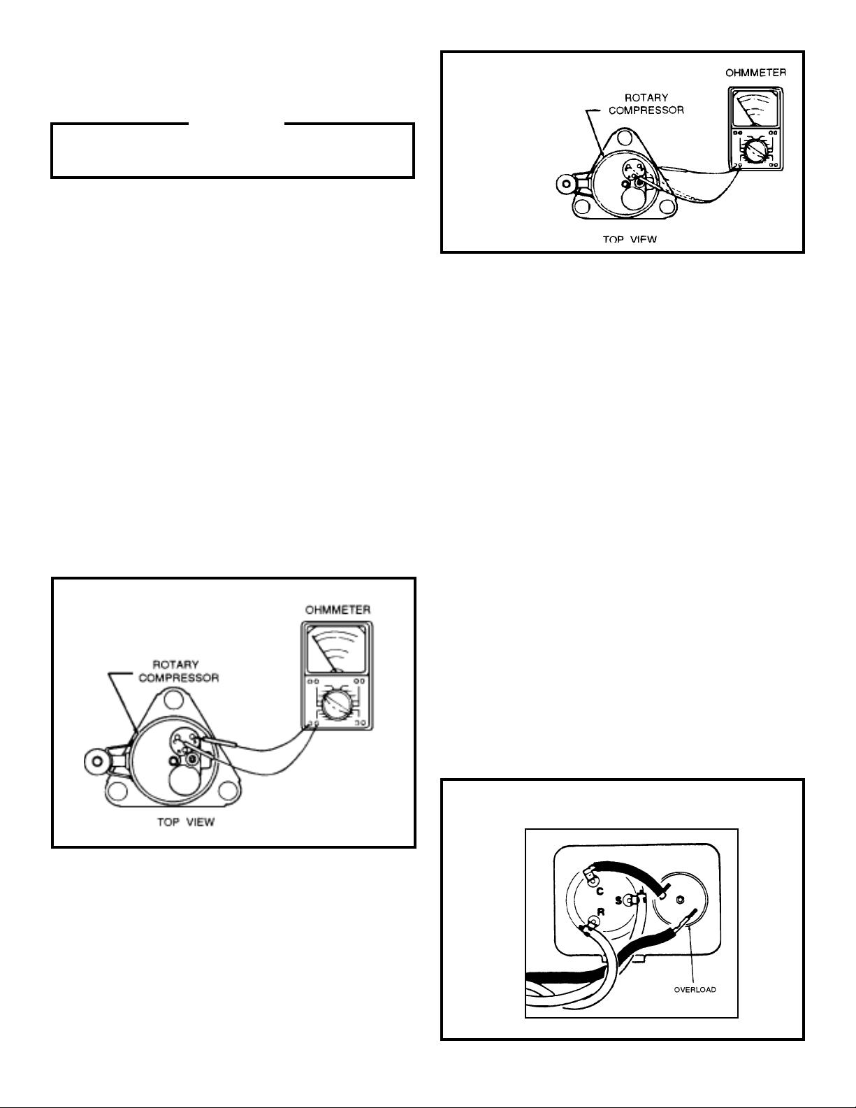
WINDING TEST
Remove compressor terminal box cover and disconnect wires
from terminals. Using an ohmmeter, check continuity across
the following: (See Figure 1)
1. Terminal "C" and "S" - no continuity - open winding replace compressor.
2. Terminal "C" and "R" - no continuity - open winding replace compressor.
3. Terminal "R" and "S" - no continuity - open winding replace compressor.
Figure 2
Typical Ground Test
CHECKING COMPRESSOR EFFICIENCY
The reason for compressor inefficiency is normally due to broken
or damaged suction and/or discharge valves, reducing the ability
of the compressor to pump refrigerant gas.
This condition can be checked as follows:
1. Install a piercing valve on the suction and discharge or
liquid process tube.
2. Attach gauges to the high and low sides of the system.
3. Start the system and run a “cooling or heating
performance test.”
If test shows:
A. Below normal high side pressure
B. Above normal low side pressure
C. Low temperature difference across coil
The compressor valves are faulty - replace the
compressor.
Figure 1
GROUND TEST
Use an ohmmeter set on its highest scale. Touch one lead to
the compressor body (clean point of contact as a good connection is a must) and the other probe in turn to each compressor terminal (see Figure 2.) If a reading is obtained, the
compressor is grounded and must be replaced.
THERMAL OVERLOAD (External)
Some compressors are equipped with an external overload
which is located in the compressor terminal box adjacent to
the compressor body (See Figure 3.)
The overload is wired in series with the common motor
terminal. The overload senses both major amperage and
compressor temperature. High motor temperature or
amperage heats the disc causing it to open and break the
circuit to the common motor terminal.
Figure 3- External Overload
14
Heat generated within the compressor shell is usually due to:
1. High amperage
2. Low refrigerant charge
3. Frequent recycling
4. Dirty condenser
FAN MOTOR - TEST
1. Determine that capacitor is serviceable.
2. Disconnect fan motor wires from fan speed switch or
system switch.
3. Apply "live" test cord probes on black wire and common
terminal of capacitor . Motor should run at high speed.
TERMINAL OVERLOAD - TEST
(Compressor - External T ype)
1. Remove overload.
2. Allow time for overload to reset before attempting to
test.
3. Apply ohmmeter probes to terminals on overload wires.
There should be continuity through the overload.
TERMINAL OVERLOAD (Internal)
Some model compressors are equipped with an internal
overload. The overload is embedded in the motor windings
to sense the winding temperature and/or current draw. The
overload is connected in series with the common motor
terminal.
Should the internal temperature and/or current draw become
excessive, the contacts in the overload will open, turning off
the compressor. The overload will automatically reset, but
may require several hours before the heat is dissipated.
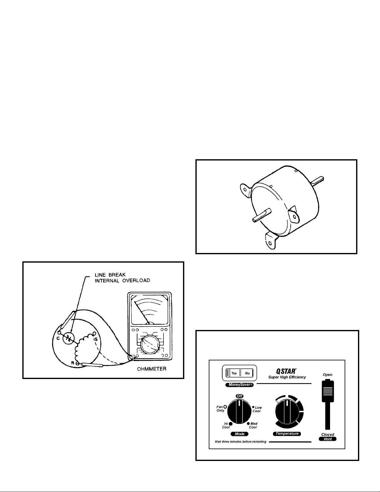
CHECKING THE INTERNAL OVERLOAD
(See Figure 4)
4. Apply "live" test cord probes on red wire and common
terminal of capacitor . Motor should run at low speed.
5. Apply "live" test cord probes on each of the remaining
wires from the speed switch or system switch to test
intermediate speeds. If the control is in the
"MoneySaver" mode and the thermostat calls for
cooling, the fan will start - then stop after approximately
2 minutes; then the fan and compressor will start
together approximately 2 minutes later.
Figure 5
Fan Motor
Figure 4
Internal Overload
1. With no power to unit, remove the leads from the compressor terminals.
2. Using an ohmmeter, test continuity between terminals
C-S and C-R. If no continuity , the compressor overload
is open and the compressor must be replaced.
FAN MOTOR
A single phase permanent split capacitor motor is used to drive
the evaporator blower and condenser fan. A self-resetting overload is located inside the motor to protect against high temperature and high amperage conditions. (See Figure 5)
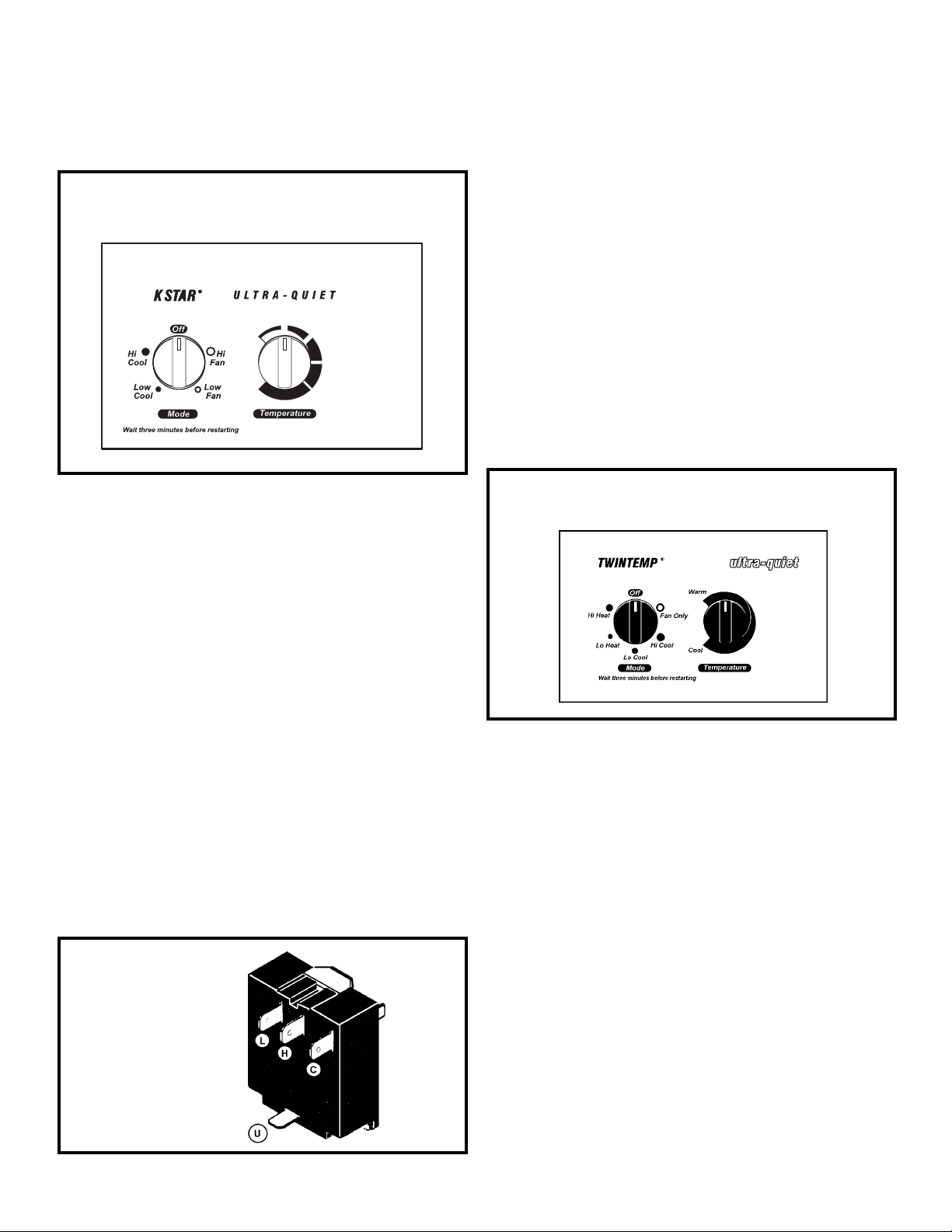
SYSTEM CONTROL PANEL- SQ Models (See Figure 6)
A five-position control switch is used to regulate the operation
of the fan motor and compressor. The compressor can be
operated with the fan operating at low, medium or high speed.
The fan motor can also be operated independently on medium
speed. See switch section as indicated on the decorative
control panel.
Figure 6
System Control Panel (SQ Models Only)
15
SYSTEM CONTROL SWITCH - TEST (See Figure 7)
Disconnect the leads from the control switch. There must be
continuity as follows:
1. "Off" Position - no continuity between terminals.
2. "Lo Cool" Position - between terminals "L1" and "C", "Lo"
and MS".
3. "Med Cool" Position - between terminals "L1" and "C", "M"
and "MS".
4. "Hi Cool" Position - between terminals L1" and "C", "H"
and "MS".
5. "Fan Only" Position - between terminals "L1" and "2".
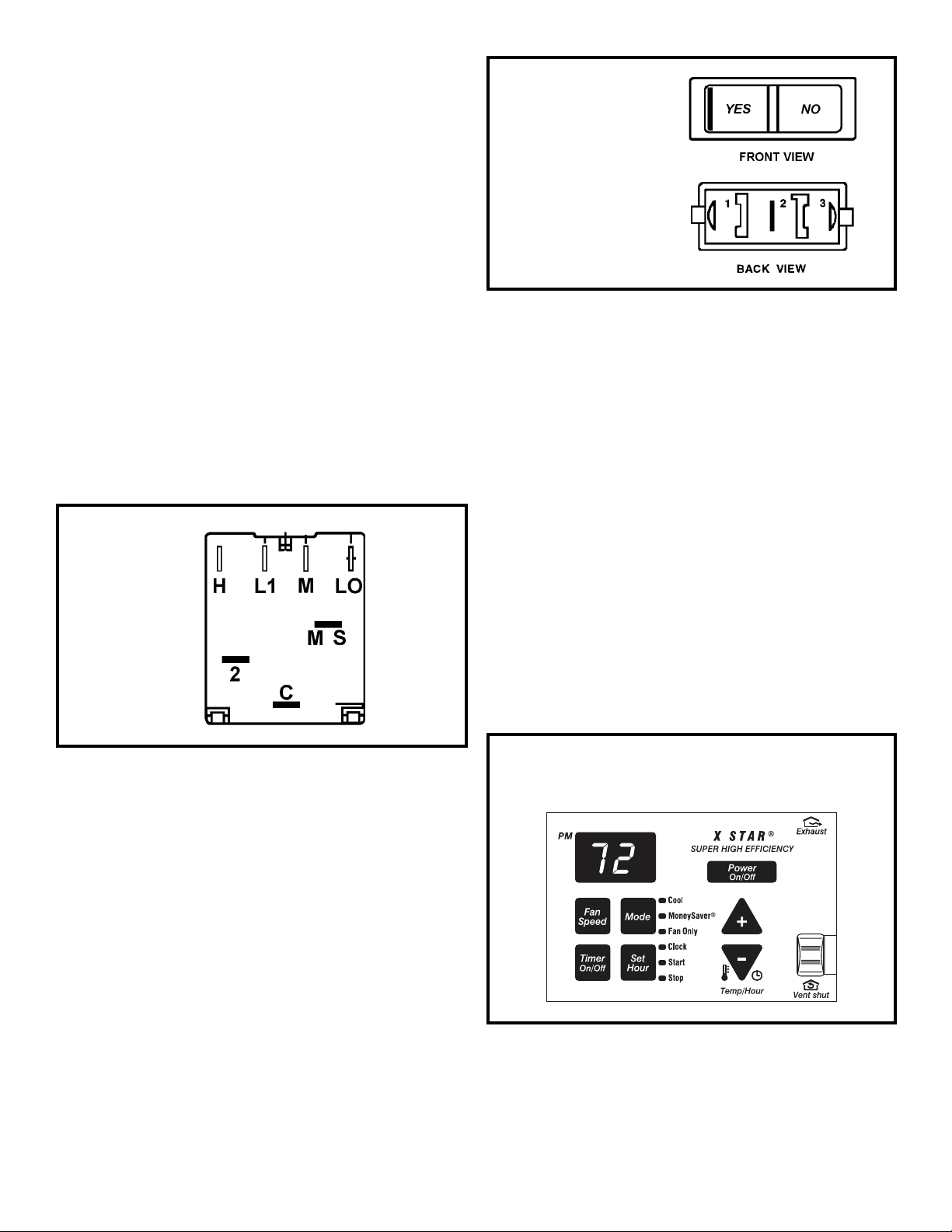
Rocker Switch
Figure 8
SYSTEM CONTROL PANEL (XQ MODELS ONLY)
(See Figure 9)
RESISTOR
(Heat Anticip ator) (SQ Only)
Failure of the resistor will cause prolonged "off" and "on" cycles
of the unit. When replacing a resistor, be sure and use the
exact replacement. Resistor rating 1 15 V olts 12500 ohm, 1.05
watts.
Figure 7
System Switch
(SQ Only)
MONEYSAVER® SWITCH (Rocker Switch- See Figure 8)
This rocker switch can be depressed to either YES or NO. In
the YES position you will get the most economical operation.
Both the fan and the compressor will cycle on and off together ,
maintaining the selected temperature at a more constant level
and reducing the humidity more efficiently. This control will
only operate when the unit is in a cooling mode. In the NO
position, the fan will run constantly as long as the unit is in the
cooling mode. Disconnect leads from switch. Depress switch
to function being tested.
1. Power button turns the unit on and off.
2. Fan Speed button allows selection between three cooling speeds and fan only .
3. The mode button allows the unit to switch between modes
(i.e., fan only, cooling, etc.).
4. Timer on/off button allows for programmed on and off
times (one hour increments).
5. The plus and minus buttons allows adjustments for room
air temperature.
6. Set hour button enables the unit’s timer on/off feature to
operate for times selected.
7. Exhaust/vent shut feature (if applicable) allows for room
air to continuously recalculate or if enabled, to exhaust
stale air.
Note: Please refer the troubleshooting guides on page if the
control is malfunctioning.
Figure 9
System Control Panel (XQ Models Only)
1. When YES is depressed, there should be continuity
between terminals "1" and "2."
2. When NO is depressed, there should be continuity
between terminals "2" and "3."
16
SYSTEM CONTROL PANEL
("KQ" Models Only- See Figure 10)
The KQ Model unit uses a five position control switch to regulate the operation of the unit. Function of each position (clockwise rotation) is as follows:
SYSTEM CONTROL PANEL
EQ Model Only (See Figure 12 )
The EQ Model unit uses a six-position control switch to regulate
the operation of the unit. Function of each position (clockwise
rotation) is as follows:
1. “Off” Turns everything off.
Figure 10
System Control Panel (KQ Models Only)
1. "Off" - Turns everything off.
2. "Hi Fan" - Maximum circulation of filtered room air (no
cooling.)
3. "Low Fan" - Fan runs slower for less circulation of filtered room air.
4. "Low Cool" - Fan runs slowly for quiet operation when
maximum cooling is not needed.
5. "Hi Cool" - Highest fan speed for maximum cooling.
2. “Fan Only” To circulate filtered room air, but no cooling
or heating
3. “Hi Cool” Fan runs continuously, compressor goes on
and off to maintain the selected room temperature
4. “Lo Cool” fan runs continuously, compressor goes on and
off to maintain the selected room temperature.
5. “Lo Heat” Fan runs continuously, heating turns on and
off to maintain the selected room temperature.
6. Hi Heat” Fan runs continuously, heating turns on and of f
to maintain the selected room temperature.
Figure 12
System Control Panel (EQ Models only)
SYSTEM CONTROL SWITCH - TEST (See Figure 1 1) Turn knob
to phase of switch to be tested. There must be continuity as follows:
1. "Hi Fan" Position - between terminals "L1" and "H".
2. "Low Fan" Position - between terminals "L1" and "L".
3. "Low Cool" Position - between terminals "L1" and "L" and
"C".
4. "Hi Cool" Position - between terminals "L1" and "H" and "C".
Figure 11
System Control Switch
(KQ Models Only)
SYSTEM CONTROL SWITCH – TEST (See Figure 13)
Turn knob to phase of switch to be tested. There must be
continuity as follows:
1. “Fan Only” Position – between terminals “MS” and “H”
2. “Hi Cool” Position – between terminals “L1” and “C” and
“MS” and “H”
3. “Low Cool” Position – between terminals “L1” and “C”
and “MS” and “LO”
4. “Low Heat” Position – between terminals “L2” and “2”
and “MS” and “LO”
5. “Hi Heat” Position – between terminals “L2” and “2” and
“MS” and “H”
17
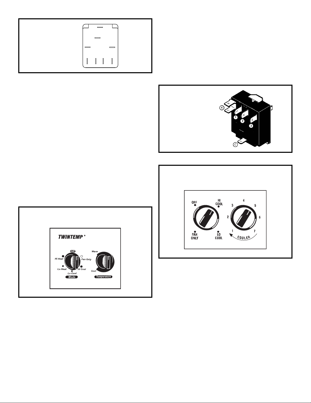
Figure 13
System Control Switch
(EQ Models)
MS
LO
L1
B1
L2
C
H
2
SYSTEM CONTROL PANEL ("YQ" Model Only)
(See Figure 14)
The YQ Model unit uses a six position control switch to regulate
the operation of the unit. Function of each position (Clockwise
rotation) is as follows:
1. "Off" - Turns everything off.
2. "Fan Only" - To circulate filtered room air, but no cooling
or heating.
3. "Hi Cool" - Fan runs continuously, compressor goes on
and off to maintain the selected room temperature.
4. "Lo Cool" - Fan runs continuously, compressor goes on
and off to maintain the selected room temperature.
5. "Lo Heat" - Fan Runs continuously, heating turns on and
off to maintain the selected room temperature.
4. "Lo Heat" Position - between terminals "C" and "2", and
"C" and "4".
5. "Hi Heat" Position - between terminals "C" and "1", and
"C" and "4".
ROT ARY (SYSTEM) SWITCH: "SC" Model (See Figure 16)
A rotary four position switch is used to turn on the unit and
select the operation desired. Switch selection is as follows:
Figure 15
System Control Switch
(YQ Model Only)
Figure 16
System Control Panel (SC Model Only)
6. "Hi Heat" - Fan Runs continuously, heating turns on and
off to maintain the selected room temperature.
Figure 14
System Control Panel (YQ Model Only)
SYSTEM CONTROL SWITCH - TEST (See Figure 15)
Turn knob to phase of switch to be tested. There must be
continuity as follows:
1. "Fan Only" Position - between terminals "C" and "1".
2. "Hi Cool" Position - between terminals "C" and "1", "C"
and "3".
3. "Lo Cool" Position - between terminals "C" and "2", and
"C" and "3".
1. "Hi Cool" T urns on the compressor and fan at high speed
2. "Lo Cool" Turns on the compressor and fan at low speed.
3. "Fan Only" Turns on the fan at high speed.
4. "Off" Turns everything off.
The switching arrangement of the control is as follows:
(See Figure 17)
1. "Off" All contacts open.
2. "Hi Fan
Contacts closed between terminals "L1" and
"1".
3. "Hi Cool" Contacts closed between terminals "L1" to "1"
and "L1" and "C".
4. "Lo-Cool" Contacts are closed between terminals "L1"
to "2" and "L1 to "C".
18
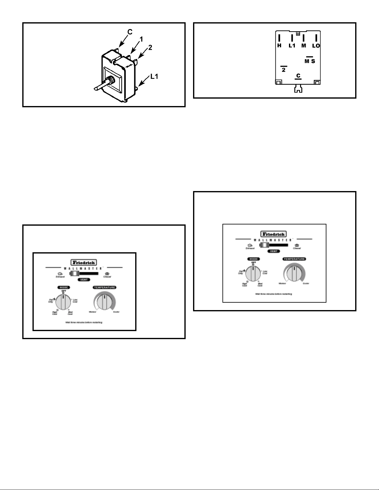
Figure 16
System Control Switch
(SC Model Only)
1. Disconnect leads from control switch.
2. Check continuity between all switch positions shown in
Figure 17.
SYSTEM CONTROL PANEL
"WS" Models (See Figure 18)
A five position control switch is used to regulate the operation
of the fan motor and compressor. The compressor can be
operated with the fan operating at low , medium or high speed.
The fan motor can also be operated independently on medium
speed. See switch section as indicated on decorative control
panel
Figure 19
System Control Switch
(WS Models)
SYSTEM CONTROL SWITCH "WE" & "WY" Models
(See Figure 20)
An eight position switch is used to regulate the operation of
the fan motor, compressor and electric heater. The unit can
be operated in cooling or heating mode with the compressor
or electric heater on and the fan motor operating on low,
medium or high speed.
The fan motor can also be operated independently on medium
speed. See switch section as indicated on decorative control panel.
Figure 20
System Control Panel
(WE & WY Models)
Figure 18
System Control Panel (WS Models)
SYSTEM CONTROL SWITCH - TEST
Disconnect leads from control switch (See Figure 19)
There must be continuity as follows:
1. "Off" Position - no continuity between terminals.
2. "Lo Cool" Position - between terminals "L1" and "C", "LO"
and "MS."
3. "Med Cool" Position - between terminals "L1" and "C", "M"
and "MS".
4. "Hi Cool" Position - between terminals "L1" and C", "H"
and "MS."
5. "Fan Only" Position - between terminals "L1" and "2."
SYSTEM CONTROL SWITCH - TEST (See Figure 21)
Disconnect leads from control switch. Turn control to position
being tested. There must be continuity as follows:
1. "Off" Position-no continuity between terminals.
2. "Lo Cool" Position-between terminals "C" and "3", "C2"
and "2", "LO" and "M/S", "AR" and "5".
3. "Med Cool" Position-between terminals "C" and "3",
"C2" and "2", "M" and "M/S", "AR" and "5".
4. "Hi Cool" Position-between terminals "C" and "3", "C2"
and "2", "H" and "M/S", "AR" and "5".
5. "Hi Heat" Position-between terminals "C" and "1", "C2"
and "4", "H" and "M/S", "AR" and "5".
19
6. "Med Heat" Position-between terminals "C" and "1",
"C2" and "4", "M" and "M/S", "AR" and "5".
7. "Lo Cool" Position-between terminals "C" and "1", "C2"
and "4", "LO" and "M/S", "AR" and "5".
8. "Fan Only" Position-between terminals "L1" and "M".
Figure 21
System Control Switch
Heat Pump / Electric Heat
(WE & WY Models)
SYSTEM CONTROL SWITCH KS, SS, KM, SM, SL Models
(See Figure 22)
A five position control switch is used to regulate the operation of
the fan motor and compressor. The compressor can be operated
with the fan operating at low, medium or high speed. The fan
motor can also be operated independently on medium speed.
See switch section as indicated on decorative control panel.
Figure 22
System Control Panel (KS, SS, KM, SM, SL)
SYSTEM CONTROL SWITCH - TEST (See Figure 23)
Disconnect leads from control switch. There must be continuity
as follows:
1. "Off" Position - no continuity between terminals.
2. "Lo Cool" Position - between terminals "L1" and "C," "LO"
and "MS."
3. "Med Cool" Position - between terminals "L1" and "C,"
"M" and "MS."
4. "Hi Cool" Position - between terminals "L1" and "C,"
"H"and "MS."
5. "Fan Only" Position - between terminals "L1" and "2."
Figure 23
System Control Switch
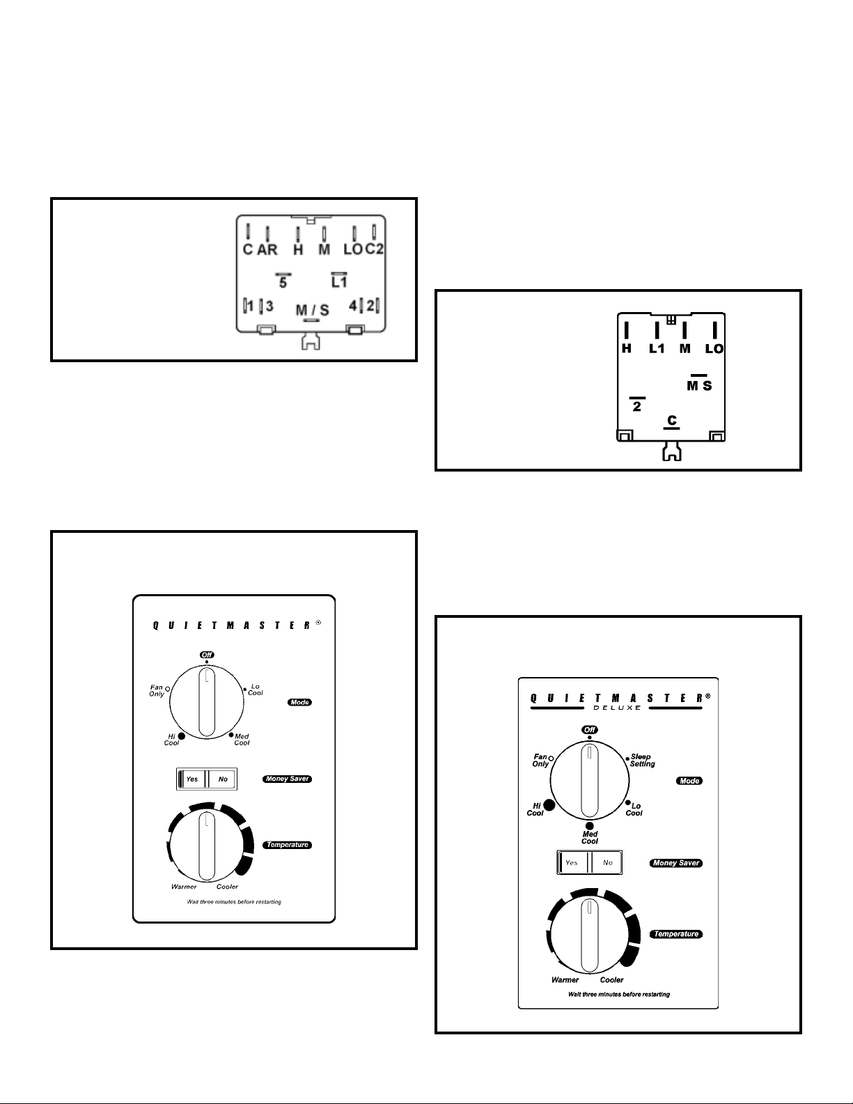
SYSTEM CONTROL PANEL (See Figure 24)
A six-position control switch is used to regulate the operation of
the fan motor and compressor. The compressor can be operated
with the fan operating at low, medium or high speed. The fan
motor can also be operated independently on medium speed.
See switch section as indicated on decorative control panel.
Figure 24
System Control Panel - Deluxe Series (RS & RM)
20
 Loading...