


Instructions for use and installation
GB
Cooker Hood
|
Istruzioni per l’uso e l’installazione |
|
IT |
||
|
Cappa |
|
|
||
|
Mode d’emploi et installation |
|
FR |
||
Hotte de Cuisine |
||
|
||
|
Bedienungsanleitung und Einrichtung |
|
DE |
||
Dunstabzugshaube |
||
|
||
|
Kullanım ve montaj talimatları |
|
TR |
||
Davlumbaz |
||
|
FGL 6015 XS
FGL 7015 XS
FGL 9015 XS

INDEX
EN
RECOMMENDATIONS AND SUGGESTIONS ...................................................................................................................... |
3 |
CHARACTERISTICS.............................................................................................................................................................. |
4 |
INSTALLATION ...................................................................................................................................................................... |
5 |
USE......................................................................................................................................................................................... |
8 |
MAINTENANCE...................................................................................................................................................................... |
9 |
INDICE
IT
CONSIGLI E SUGGERIMENTI ............................................................................................................................................ |
10 |
CARATTERISTICHE ............................................................................................................................................................ |
11 |
INSTALLAZIONE.................................................................................................................................................................. |
12 |
USO ...................................................................................................................................................................................... |
15 |
MANUTENZIONE ................................................................................................................................................................. |
16 |
SOMMAIRE
FR
CONSEILS ET SUGGESTIONS .......................................................................................................................................... |
17 |
CARACTERISTIQUES ......................................................................................................................................................... |
18 |
INSTALLATION .................................................................................................................................................................... |
19 |
UTILISATION........................................................................................................................................................................ |
22 |
ENTRETIEN.......................................................................................................................................................................... |
23 |
INHALTSVERZEICHNIS
DE
EMPFEHLUNGEN UND HINWEISE |
....................................................................................................................................24 |
CHARAKTERISTIKEN.......................................................................................................................................................... |
25 |
MONTAGE............................................................................................................................................................................ |
26 |
BEDIENUNG......................................................................................................................................................................... |
29 |
WARTUNG............................................................................................................................................................................ |
30 |
IÇERIKLER |
TR |
TAVSIYELER VE ÖNERILER .............................................................................................................................................. |
31 |
ÖZELLIKLER ........................................................................................................................................................................ |
32 |
MONTAJ ............................................................................................................................................................................... |
33 |
KULLANIM ............................................................................................................................................................................ |
36 |
BAKIM................................................................................................................................................................................... |
37 |
2
RECOMMENDATIONS AND SUGGESTIONS
 The Instructions for Use apply to several versions of this appliance. Accordingly, you may find descriptions of individual features that do not apply to your specific appliance.
INSTALLATION
•The manufacturer will not be held liable for any damages resulting from incorrect or improper installation.
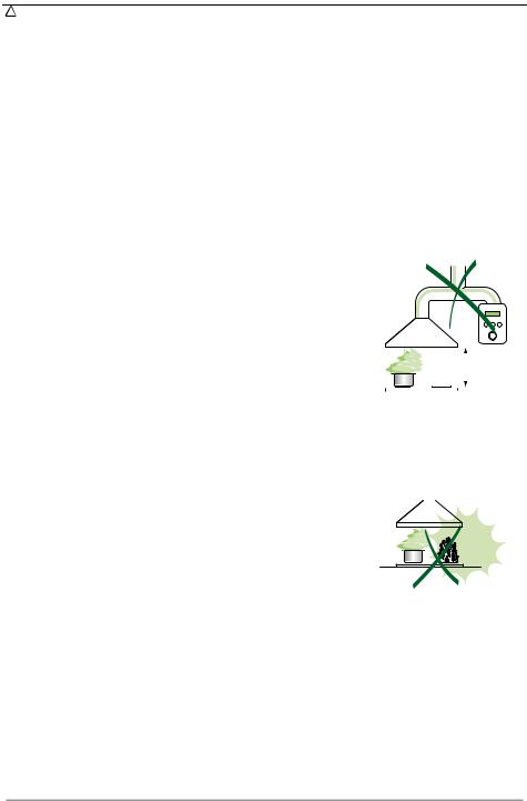
•The minimum safety distance between the cooker top and the extractor hood is 650 mm (some models can be installed at a lower height, please refer to the paragraphs on working dimensions and installation).
•Check that the mains voltage corresponds to that indicated on the rating plate fixed to the inside of the hood.
•For Class I appliances, check that the domestic power supply guarantees adequate earthing.
Connect the extractor to the exhaust flue through a pipe of minimum diameter 120 mm. The route of the flue must be as short as possible.
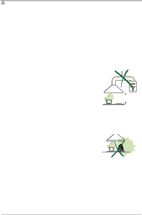
•Do not connect the extractor hood to exhaust ducts carrying combustion fumes (boilers, fireplaces, etc.).
•If the extractor is used in conjunction with non-electrical appliances (e.g. gas burning appliances), a sufficient degree of aeration must be guaranteed in the room in order to prevent the backflow of exhaust gas. The kitchen must have an opening communicating directly with the open air in order to guarantee the entry of clean air.
USE
• The extractor hood has been designed exclusively for domestic use to elimi- |
|
|
|
|
|
|
||
|
|
|
|
|
|
|||
nate kitchen smells. |
|
|
|
|
|
|
||
• Never use the hood for purposes other than for which it has been designed. |
|
650 mm min. |
||||||
• Never leave high naked flames under the hood when it is in operation. |
|
|
|
|
|
|
||
• Adjust the flame intensity to direct it onto the bottom of the pan only, making |
|
|
|
|
|
|
|
|
|
|
|
|
|
|
|
|
|
sure that it does not engulf the sides. |
|
|
|
|
|
|
||
•Deep fat fryers must be continuously monitored during use: overheated oil can burst into flames.
•Do not flambè under the range hood; risk of fire
•This appliance is not intended for use by persons (including children) with reduced physical, sensory or mental capabilities, or lack of experience and knowledge, unless they have been given supervision or instruction concerning use of the appliance by a person responsible for their safety.
•Children should be supervised to ensure that they do not play with the appli-
ance.
MAINTENANCE
• Switch off or unplug the appliance from the mains supply before carrying out any maintenance work.
•Clean and/or replace the Filters after the specified time period (Fire hazard).
•Clean the hood using a damp cloth and a neutral liquid detergent.
The symbol  on the product or on its packaging indicates that this product may not be treated as household waste. Instead it shall be handed over to the applicable collection point for the recycling of electrical and electronic equipment. By ensuring this product is disposed of correctly, you will help prevent potential negative consequences for the environment and human health, which could otherwise be caused by inappropriate waste handling of this product. For more detailed information about recycling of this product, please contact your local city office, your household waste disposal service or the shop where you purchased the product.
EN |
|
3 |
|
3 |

CHARACTERISTICS
|
|
|
Dimensions |
|
|
|
|
|
|
|
|
63 |
126 |
41 |
|
|
|
|
|
|
|
||
|
|
|
|
|
|
81 |
|
540 |
|
|
Min. 670 |
Max. 1000 |
|
|
|
|
252 |
6 |
|
|
|
|
|
48 |
|
|
|
|
|
|
|
|
|
|
598 - 698 - 798 - 898 |
|
|
|
|
|
|
|
300 |
|
|
|
|
|
|
|
150 |
|
|
|
|
|
|
108 |
|
260 |
Min. |
|
Min. |
|
|
|
500mm |
650mm |
|||
520 |
420 |
|
|
|
|
|
|
|
|
|
530 |
|
|
|
|
Components
Ref. Q.ty Product Components
11 Hood Body, complete with: Controls, Light, Blower, Filters
2 |
1 |
Telescopic Chimney comprising: |
2.1 |
1 |
Upper Section |
2.2 |
1 |
Lower Section |
9 |
1 |
Reducer Flange ø 150-120 mm |
14.1 |
2 |
Air Outlet Connection Extension |
15 |
1 |
Air Outlet Connection |
Ref. |
Q.ty |
Installation Components |
7.2.1 |
2 |
Upper Chimney Section Fixing Brackets |
7.3 |
1 |
Air Outlet Connection Support |
11 |
6 |
Wall Plugs |
12a |
6 |
Screws 4,2 x 44,4 |
12c |
6 |
Screws 2,9 x 9,5 |
|
Q.ty |
Documentation |
|
1 |
Instruction Manual |
15
14.1
7.3 |
12a |
7.2.1 |
11 |
|
9
2.1 |
12c |
|
2
2.2
11 |
12a |
1
EN |
|
4 |
|
4 |
INSTALLATION
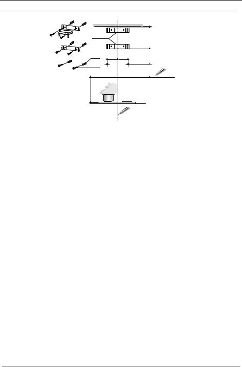
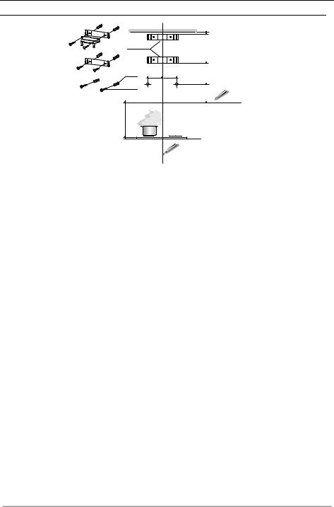
Wall drilling and bracket fixing
7.2.1
11 |
116 116 |
12a |
|
650 min.
306 X 1÷2
Wall marking:
•Draw a vertical line on the supporting wall up to the ceiling, or as high as practical, at the centre of the area in which the hood will be installed.
•Draw a horizontal line at 650 mm above the hob.
•Place bracket 7.2.1 on the wall as shown about 1-2 mm from the ceiling or upper limit aligning the centre (notch) with the vertical reference line.
•Mark the wall at the centres of the holes in the bracket.
•Place bracket 7.2.1 on the wall as shown at X mm below the first bracket (X = height of the upper chimney section supplied), aligning the centre (notch) with the vertical line.
•Mark the wall at the centres of the holes in the bracket.
•Mark a reference point as indicated at 116 mm from the vertical reference line and 306 mm above the horizontal reference line.
•Repeat this operation on the other side.
•Drill ø 8 mm holes at all the centre points marked.
•Insert the wall plugs 11 in the holes.
•Fix the lower bracket 7.2.1 using the 12a screws (4,2 x 44,4) supplied.
•Fix the upper bracket 7.2.1 and the air outlet connection support 7.3 together using the 2 screws 12a (4,2 x 44,4) supplied.
•Insert the two screws 12a (4,2 x 44,4) supplied in the hood body fixing holes, leaving a gap of 5-6 mm between the wall and the head of the screw.
EN |
|
5 |
|
5 |
|
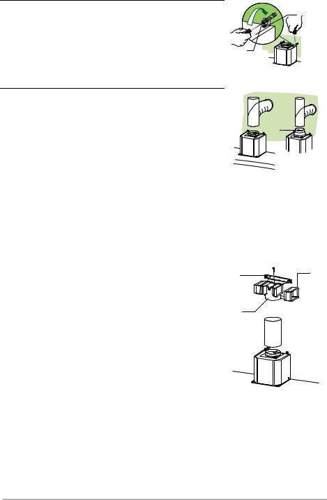
Mounting the hood body |
|
• |
Before attaching the hood body, tighten the two screws Vr lo- |
Vr |
|
cated on the hood body mounting points. |
|
|
|
|
• Hook the hood body onto the screws 12a. |
|
|
• Fully tighten the support screws 12a. |
|
|
• |
Adjust the screws Vr to level the hood body. |
12a |
Connections
DUCTED VERSION AIR EXHAUST SYSTEM
When installing the ducted version, connect the hood to the chimney using either a flexible or rigid pipe ø 150 or 120 mm, the choice of which is left to the installer.
•To install a ø 120 mm air exhaust connection, insert the reducer flange 9 on the hood body outlet.
•Fix the pipe in position using sufficient pipe clamps (not supplied).
•Remove any activated charcoal filters.
ø 150 |
ø 120 |
9
RECIRCULATION VERSION AIR OUTLET
•Insert the connection extension pieces laterally 14.1 in connection 15.
•Insert the Connector 15 into the Support bracket 7.3 and fix it with a screw.
•Make sure that the outlet of the extension pieces 14.1 is horizontally and vertically aligned with the chimney outlets.
•Connect the air outlet connection 15 to the hood body outlet
using either a flexible or rigid pipe ø 150 mm, the choice of which is left to the installer.
• Ensure that the activated charcoal filters have been inserted.
7.3 |
14.1 |
|
|
15 |
|
|
ø 150 |
EN |
|
6 |
|
6 |
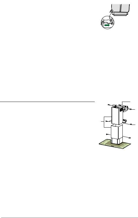
ELECTRICAL CONNECTION
•Connect the hood to the mains through a two-pole switch having a contact gap of at least 3 mm.
•Remove the grease filters (see paragraph Maintenance) being sure that the connector of the feeding cable is correctly inserted in the socket placed on the side of the fan.
Flue assembly
Upper exhaust flue
•Slightly widen the two sides of the upper flue and hook them behind the brackets 7.2.1, making sure that they are well seated.
•Secure the sides to the brackets by using the 4 screws 12c (2,9 x 9,5) supplied.
•Make sure that the outlet of the extensions pieces is aligned with the chimney outlets.
Lower exhaust flue
• Slightly widen the two sides of the flue and hook them between the upper flue and the wall, making sure that they are well seated.
•Fix the lower part laterally to the hood body by using the 2 screws 12c (2,9 x 9,5) supplied.
7.2.1
12c
2.1
2
12c |
2.2
12c
EN |
|
7 |
|
7 |
USE
|
|
|
|
T1 |
|
|
|
|
|
|
|
|
|
|
|
|
|
|
|
|
|
|
|
|
|
|
|
|
|
|
T2 |
T3 |
L |
||
|
|
|
|
|
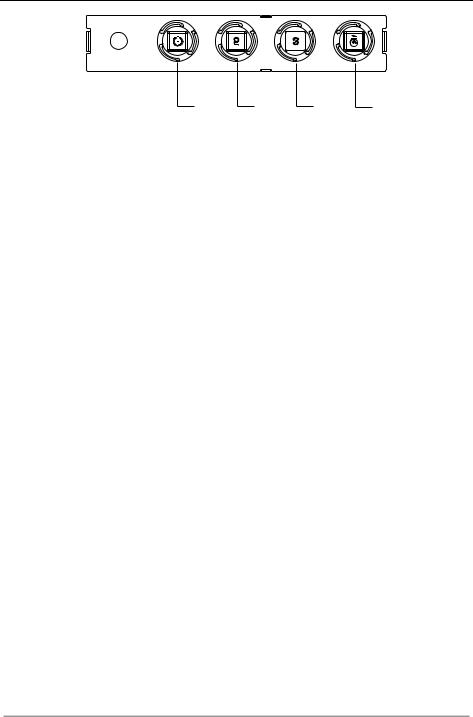
Control panel |
|
|
|
BUTTON |
LED |
FUNCTIONS |
|
|
|
|||
T1 |
Speed |
On |
Turns the Motor on at Speed one. |
|
||||
|
|
|
Turns the Motor off. |
|
|
|
||
T2 |
Speed |
On |
Turns the Motor on at Speed two. |
|
||||
T3 |
Speed |
Fixed |
When pressed briefly, turns the Motor on at Speed three. |
|||||
L |
Light |
|
Turns the Lighting System on and off. |
|
||||
|
|
|
|
|
|
|
|
|
Warning: Button T1 turns the motor off, after first passing to speed one.
EN |
|
8 |
|
8 |
MAINTENANCE
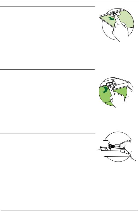
Grease filters
CLEANING METAL SELFSUPPORTING GREASE FILTERS
•The filters must be cleaned every 2 months of operation, or more frequently for particularly heavy usage, and can be washed in a dishwasher.
•Remove the filters one at a time by pushing them towards the back of the group and pulling down at the same time.
•Wash the filters, taking care not to bend them. Allow them to dry before refitting.
•When refitting the filters, make sure that the handle is visible on the outside.
Activated charcoal filter (Recirculation version)
REPLACING THE ACTIVATED CHARCOAL FILTER
•The filter is not washable and cannot be regenerated, and must be replaced approximately every 4 months of operation, or more frequently for particularly heavy usage.
•Remove the metal grease filters.
•Remove the saturated activated carbon filter by releasing the fixing hooks.
•Fit the new filter by hooking it into its seating.
•Refit the metal grease filters.
Lighting
LIGHT REPLACEMENT
40 W incandescent light.
•Remove the metal grease filters.
•Unscrew the bulbs and replace them with new ones having the same characteristics.
•Replace the metal grease filters.
EN |
|
9 |
|
9 |
CONSIGLI E SUGGERIMENTI
 Questo libretto di istruzioni per l'uso è previsto per più versioni dell' apparecchio. É possibile che siano descritti singoli particolari della dotazione, che non riguardano il Vostro apparecchio.
INSTALLAZIONE
•Il produttore declina qualsiasi responsabilità per danni dovuti ad installazione non corretta o non conforme alle regole dell’arte.
•La distanza minima di sicurezza tra il Piano di cottura e la Cappa deve essere di 650 mm, (alcuni modelli possono essere installati ad un’altezza inferiore, fare riferimento ai paragrafi ingombro e installazione).
•Verificare che la tensione di rete corrisponda a quella riportata nella targhetta posta all’interno della Cappa.
•Per Apparecchi in Classe Ia accertarsi che l’impianto elettrico domestico garantisca un corretto scarico a terra.
•Collegare la Cappa all’uscita dell’aria aspirata con tubazione di diametro pari o superiore a 120 mm. Il percorso della tubazione deve essere il più breve possibile.
•Non collegare la Cappa a condotti di scarico dei fumi prodotti da combustione (caldaie, caminetti, ecc.).
•Nel caso in cui nella stanza vengano utilizzati sia la Cappa che apparecchi non azionati da energia elettrica (ad esempio apparecchi utilizzatori di gas), si deve
provvedere ad una aerazione sufficiente dell’ambiente. Se la cucina ne fosse sprovvista, praticare un’apertura che comunichi con l’esterno, per garantire il richiamo d’aria pulita.
USO
• La Cappa è stata progettata esclusivamente per uso domestico, per abbattere gli |
|
|
|
|
|
|
|
|
|
||
|
odori della cucina. |
|
|
|
|
• |
Non fare mai uso improprio della Cappa. |
|
650 mm min. |
||
• |
Non lasciare fiamme libere a forte intensità sotto la Cappa in funzione. |
|
|
|
|
•Regolare sempre le fiamme in modo da evitare una evidente fuoriuscita laterale delle stesse rispetto al fondo delle pentole.
•Controllare le friggitrici durante l’uso: l’olio surriscaldato potrebbe infiammarsi.
•Non preparare alimenti flambè sotto la cappa da cucina; pericolo d'incendio.
•Questo apparecchio non deve essere utilizzato da persone (bambini inclusi) con ridotte capacità psichiche, sensoriali o mentali, oppure da persone senza esperienza e conoscenza, a meno che non siano controllati o istruiti all’uso dell’apparecchio da persone responsabili della loro sicurezza.
•I bambini devono essere supervisionati per assicurarsi che non giochino con l’apparecchio.
MANUTENZIONE
• Prima di procedere a qualsiasi operazione di manutenzione, disinserire la Cappa togliendo la spina elettrica o spegnendo l’interruttore generale.
•Effettuare una scrupolosa e tempestiva manutenzione dei Filtri secondo gli intervalli consigliati (Rischio di incendio).
•Per la pulizia delle superfici della Cappa è sufficiente utilizzare un panno umido e detersivo liquido neutro.
Il simbolo  sul prodotto o sulla confezione indica che il prodotto non deve essere considerato come un normale rifiuto domestico, ma deve essere portato nel punto di raccolta appropriato per il riciclaggio di apparecchiature elettriche ed elettroniche. Provvedendo a smaltire questo prodotto in modo appropriato, si contribuisce a evitare potenziali conseguenze negative per l’ambiente e per la salute, che potrebbero derivare da uno smaltimento inadeguato del prodotto. Per informazioni più dettagliate sul riciclaggio di questo prodotto, contattare l’ufficio comunale, il servizio locale di smaltimento rifiuti o il negozio in cui è stato acquistato il prodotto.
IT |
|
1 |
|
10 |
CARATTERISTICHE
|
|
|
Ingombro |
|
|
|
|
|
|
|
|
63 |
126 |
41 |
|
|
|
|
|
|
|
||
|
|
|
|
|
|
81 |
|
540 |
|
|
Min. 670 |
Max. 1000 |
|
|
|
|
252 |
6 |
|
|
|
|
|
48 |
|
|
|
|
|
|
|
|
|
|
598 - 698 - 798 - 898 |
|
|
|
|
|
|
|
300 |
|
|
|
|
|
|
|
150 |
|
|
|
|
|
|
108 |
|
260 |
Min. |
|
Min. |
|
|
|
500mm |
650mm |
|||
520 |
420 |
|
|
|
|
|
|
|
|
|
530 |
|
|
|
|
Componenti
Rif. Q.tà Componenti di Prodotto
11 Corpo Cappa completo di: Comandi, Luce, Gruppo Ventilatore, Filtri
2 |
1 |
Camino Telescopico formato da: |
2.1 |
1 |
Camino Superiore |
2.2 |
1 |
Camino Inferiore |
9 |
1 |
Flangia di Riduzione ø 150-120 mm |
14.1 |
2 |
Prolunga Raccordo Uscita Aria |
15 |
1 |
Raccordo Uscita Aria |
Rif. |
Q.tà |
Componenti di Installazione |
7.2.1 |
2 |
Staffe Fissaggio Camino Superiore |
7.3 |
1 |
Staffa Sostegno Raccordo |
11 |
6 |
Tasselli |
12a |
6 |
Viti 4,2 x 44,4 |
12c |
6 |
Viti 2,9 x 9,5 |
|
Q.tà |
Documentazione |
|
1 |
Libretto Istruzioni |
15
14.1
7.3 |
12a |
7.2.1 |
11 |
|
9
2.1 |
12c |
|
2
2.2
11 |
12a |
1
IT |
|
1 |
|
11 |
INSTALLAZIONE
Foratura Parete e Fissaggio Staffe
7.2.1
11 |
116 116 |
12a |
|
650 min.
306 X 1÷2
Tracciare sulla Parete:
•una linea Verticale fino al soffitto o al limite superiore, al centro della zona prevista per il montaggio della Cappa;
•una linea Orizzontale a: 650 mm min. sopra il Piano di Cottura.
•Appoggiare come indicato la Staffa 7.2.1 a 1-2 mm dal soffitto o dal limite superiore, allineando il suo centro (intagli) sulla linea Verticale di riferimento.
•Segnare i centri dei Fori della Staffa.
•Appoggiare come indicato la Staffa 7.2.1 a X mm sotto la prima staffa (X = altezza Camino Superiore in dotazione), allineando il suo centro (intagli) sulla linea Verticale di riferimento.
•Segnare i centri dei Fori della Staffa.
•Segnare come indicato, un punto di riferimento a 116 mm dalla linea Verticale di riferimento, e 306 mm sopra la linea Orizzontale di riferimento.
•Ripetere questa operazione dalla parte opposta.
•Forare ø 8 mm i punti segnati.
•Inserire i tasselli 11 nei fori.
•Fissare la Staffa inferiore 7.2.1 utilizzando le Viti 12a (4,2 x 44,4 ) in dotazione.
•Fissare insieme la Staffa superiore 7.2.1 e la Staffa sostegno raccordo 7.3 utilizzando le 2 viti 12a (4,2 x 44,4) in dotazione.
•Avvitare 2 Viti 12a (4,2 x 44,4) in dotazione nei fori per il fissaggio del corpo Cappa, lasciando uno spazio di 5-6 mm fra la parete e la testa della vite.
IT |
|
1 |
|
12 |
 Loading...