


T400A/W, MCD400A/W, R400A/W,
MFD400A/W, D400A/W Icemakers
Order parts online www.follettice.com
Installation, Operation and Service Manual
Following installation, please forward this manual to the appropriate operations person.
801 Church Lane • Easton, PA 18040, USA |
|
Toll free (800) 523-9361 • (610) 252-7301 |
|
Fax (610) 250-0696 • www.follettice.com |
208600R13 |

Follett Corporation
Equipment Return Policy
Follett equipment may be returned for credit under the following conditions:
1.The equipment is new and unused.
2.A return authorization number has been issued by customer service within 30 days after shipment.
3.Follett receives the equipment at the factory in Easton, PA within 30 days after issuance of the return authorization number.
4.The equipment must be returned in Follett packaging. If the packaging has been damaged or discarded, Follett will forward, at the customer’s expense, new packaging.
Note: Return freight charges are the responsibility of the customer. If equipment is returned and is damaged because of improper packaging, Follett Corporation will not be held responsible.
Credit will be issued when:
The equipment has been inspected by Follett and deemed suitable to be returned to stock.
Note: A 15% restocking charge will be deducted from the credit. If the cost to return the product to stock exceeds 15%, the actual cost will be deducted.
2

Table of contents
Welcome to Follett Corporation |
4 |
Specifications |
5 |
Installation |
7 |
Top mount icemakers (models T400A/W, MCD400A/W and MFD400A/W) |
7 |
Satellite-fill icemakers (models MCD400A/W, R400A/W) |
8 |
Ventilation |
13 |
Ice transport tube |
14 |
Start up |
16 |
Operation |
16 |
Cleaning |
16 |
Weekly exterior care |
16 |
Monthly condenser cleaning |
17 |
Semi-annual evaporator cleaning |
17 |
Service |
18 |
Icemaker operation |
18 |
Technical specifications |
19 |
Refrigeration system diagram |
19 |
Refrigeration pressure data |
19 |
Compressor data |
19 |
Gearmotor data |
20 |
MCD400A/W wiring diagram |
20 |
Electrical control system operation |
21 |
Refrigeration system |
27 |
Service procedures |
28 |
Evaporator disassembly |
28 |
Evaporator reassembly |
28 |
Gearmotor replacement |
28 |
Troubleshooting |
29 |
Replacement parts |
31 |
3

Welcome to Follett
Follett equipment enjoys a well-deserved reputation for excellent performance, long-term reliability and outstanding after-the-sale support. To ensure that this equipment delivers that same degree of service, we ask that you review the installation portion of this manual before beginning to install the unit. Our instructions are designed to help you achieve a trouble-free installation. Should you have any questions or require technical help at any time, please call our technical service group at (800) 523-9361 or (610) 252-7301.
Before you begin
After uncrating and removing all packing material, inspect the equipment for concealed shipping damage. If damage is found, notify the shipper immediately and contact Follett Corporation so that we can help in the filing of a claim,
if necessary.
Check your paperwork to determine which model you have. Follett model numbers are designed to provide information about the type and capacity of Follett equipment. Following is an explanation of the different model numbers in the 400 series.
MCD400ABT
Condenser type
|
|
Icemaker capacity and refrigerant |
A – air-cooled |
|
|
W – water-cooled |
|
|
|
400 – 400 lbs (181kg)/day, R404A |
|
|
|
|
|
Voltage |
|
||
|
D – 115V 60Hz |
|
|
Icemaker series
Nugget icemaker
MCD – Satellite-fill installation, Vision™ ice and beverage dispensers and top installation, Follett ice storage bins
R – Remote installation, Symphony™ ice and water dispensers D – Replacement icemaker, Symphony ice and water dispensers
Flake icemaker
MFD – Top installation, Follett ice storage bins
Application
V – Vision
B – Bin
H – Harmony
Configuration
S – Satellite-fill™ T – top-mount
! Important cautions
Moving parts. Do not operate with front cover removed.
Hot parts. Do not operate with cover removed.
To reduce risk of shock disconnect power before servicing.
Most ice machine cleaners contain citric or phosphoric acid, which can cause skin irritation. Read caution label on product and follow instructions carefully.
Ice is slippery. Maintain counters and floors around dispenser in a clean and ice-free condition. Ice is food. Follow recommended cleaning instructions to maintain cleanliness of delivered ice.
4
Specifications
Electrical
Each icemaker and dispenser require a separate circuit with electrical disconnect within 10 ft (6m). Equipment ground required.
Standard electrical – 115V, 60Hz, 1 phase. Maximum dispenser fuse – 15 amps, Maximum icemaker fuse – 20 amps each Maximum icemaker amperage – 11 amps each
Cord and plug provided on icemaker and dispenser
Electrical connections
Model |
Electrical connection |
Circuits required |
25FB400A/W, 50FB400A/W, 110FB400A/W |
cord & plug provided |
115/60/1, 20 amp max. fuse size |
|
|
|
25CT400A/W, 50CT400A/W, 110CT400A/W |
cord & plug provided |
115/60/1, 20 amp max. fuse size |
|
|
|
25CR400A/W, 50CR400A/W, 110CR400A/W |
dispenser, icemaker |
115/60/1, (2) circuits required |
|
and bin signal: |
dispenser: 15 amp max. fuse size |
|
cord & plug provided |
icemaker: 20 amp max. fuse size |
|
|
|
VU155R400A/W, VU300R400A/W |
dispenser, icemaker |
115/60/1, (2) circuits required |
VU155BR400A/W, VU300BR400A/W |
and bin signal: |
dispenser: 15 amp max. fuse size |
VU155R400A/WX, VU155BR400A/WX |
cord & plug provided |
icemaker: 20 amp max. fuse size |
|
|
|
VU155NR400A/W, UD300R400A/W |
dispenser, icemaker |
115/60/1, (3) circuits required |
VU155R800A/W, VU300R800A/W, |
and bin signal: |
|
VU155R800A/WX, |
cord & plug provided |
dispenser: 15 amp max. fuse size |
VU155BR800A/W, VU300BR800A/W, |
|
(2) icemakers: 20 amps max. fuse |
VU155R800A/WX |
|
size each |
|
|
|
Plumbing
3/8" OD push-in water inlet 3/4" MPT drain
3/8" FPT condenser inlet (water-cooled condenser only) 3/8" FPT condenser drain (water-cooled condenser only)
Notes: Slope to drain of 1/4" per foot (6mm per 30.4cm run) with a 1/2" min. is recommended. Water shut-off recommended within 10 feet (3m), drain to be hard piped and insulated. Separate drains for icemaker and condenser. To prevent back flow, do NOT connect drains. Follett recommends installation of an activated carbon filter in icemaker inlet water line.
Ambient
Air temperature |
100˚ F/38˚ C max. |
50˚F/10˚C min. (best performance below 80˚F/27˚C) |
Water temperature |
90˚F/32˚C max. |
40˚F/4˚C min. (best performance below 70˚F/21˚C) |
Water pressure |
70 P.S.I max. (482 kPA) |
10 P.S.I. min. (89 kPA) |
5
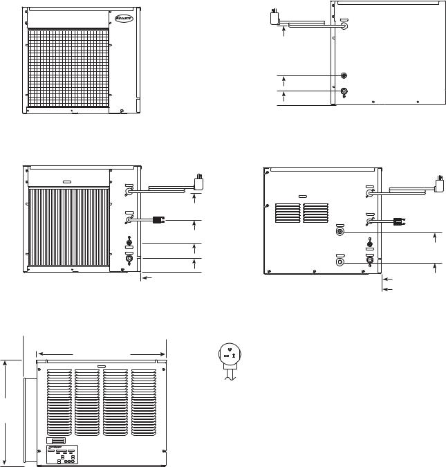
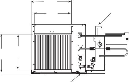
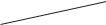
Dimensions and clearances
Entire front of icemaker must be clear of obstructions/connections to allow removal. 12" (305mm) clearance above icemaker for service.
6" (153mm) minimum clearance between exhaust side of icemaker and any adjacent equipment.
MCD400A & R400A – 18" (457mm) minimum, 10 ft (3m) maximum clearance between discharge and air intake grilles.
Front view — air-cooled |
Back view — air-cooled |
top mount |
top mount |
13.00" |
C |
|
|
(331mm) |
|
4.875" |
B |
(124mm) |
|
2.375" |
A |
(61mm) |
|
Front view — air-cooled
Satellite-fill
C
F
B
A
1.875" (48mm) 

Side view — air-cooled and water-cooled top mount and Satellite-fill
 22.75" (578mm)
  20.75" (527mm)
17.00"
(432mm)
 Satellite-fill air-cooled units only
|
Front view — water-cooled |
||
|
Satellite-fill |
|
|
|
Back view — water-cooled |
||
|
top mount |
|
|
12.875" |
|
C |
|
(327mm) |
|
|
|
8.375" |
|
F |
|
(213mm) |
D |
|
|
|
|
||
4.75" |
|
B |
|
(121mm) |
|
|
|
2.25" |
E |
A |
|
(57mm) |
|||
|
|
||
1.875" (48mm) 
 7.00" (178mm)

Icemaker plug configuration NEMA 5-20
|
|
|
|
|
|
A – 3/4" MPT drain |
|
D – 3/8" FPT condenser inlet |
|
|
B – 3/8" OD push-in water inlet |
|
E – 3/8" FPT condenser drain |
|
|
C – Electrical cord |
|
F – Bin signal cord |
|
|
|
|
|
|
|
|
|
|
|
6.875"
(175mm)
2"
(51mm)
6
Installation
Icemaker performance is very sensitive to the quality of installation. To ensure proper performance, ease of service and warranty coverage, it is critical that you follow the requirements detailed in this manual. If you cannot meet these requirements or have questions, call our technical service group immediately at (800) 523-9361 or (610) 252-7301.
Top mount icemaker on bin installation procedure (models MCD400A/WBT and MFD400A/WBT)
Install icemaker and rough-in utilities
1.Install ice storage bin in its final location.
2.Install one supplied grommet in large knockout in base of icemaker and second supplied grommet in ice hole provided in top of ice storage bin.
3.Rough in plumbing and electrical per specs provided.
4.Flush all water lines before final hook up.
5.Position icemaker with utility connections facing rear of bin.
A.If new storage bin and icemaker – position icemaker with connections facing rear of bin.
B.If using existing bin – place supplied gasket 2.5" (64mm) from front of bin (Fig. 2). Position icemaker with utility connections facing rear of bin.
6.Make final plumbing and electrical connections.
7.Working from inside bin storage area, push end of transport tube without fasteners up through grommets into icemaker, leaving about 2" (51mm) hanging down in bin.
8.Route free end of tube to evaporator port.
9.Slip a hose clamp in free end of tube.
10.Push free end of tube on evaporator port and tighten clamp, making sure clamp is positioned on evaporator side of flange (no flange on MFD400 series flake icemaker).
11.Position ice tube under float bracket retaining tab.
12.Carefully slip ice level control stat alongside transport tube through both grommets and down into bin.
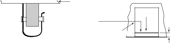
13.Run ice level control stat down through one side of cap tube fasteners attached to ice transport tube, form a 180˚ bend at end of tube and run back up through fastener (Fig. 1).
14.Adjust loop length to provide desired ice level. Loop must below end of ice transport tube.
15.Carefully bend end of cap tube to prevent it from slipping out of clamp.
Fig. 1
ice level control 
 stat fastener
ice level control stat 
Fig. 2 – Replacing existing icemakers
bin top
 ice transport tube
Apply supplied gasket to bin top as shown. Position icemaker on bin top.
bin top  top view shown
add gasket
existing gasket
2.5"
(64mm)
front of icemaker
Before turning power on
1.Clean and sanitize ice storage bin in accordance with cleaning procedure in ice storage bin installation information packed with ice storage bin.
2.Turn water to icemaker on.
3.Remove cover on float reservoir.
4.Push down on float to force water out overflow tube and into evaporator drain pan.
5.Check that water drains freely from evaporator drain pan.
6.Lift float and check that float valve shuts off incoming water when raised.
7
After turning power on
1.Turn power to icemaker on and confirm that gearmotor, compressor and fan motor start immediately.
2.Check that ice begins to enter bin within approximately 10 minutes.
3.With icemaker running, check that float reservoir water level is approximately 3/8" (10mm) below internal overflow and adjust to this level (raised line on side of reservoir) if necessary.
4.After making ice for 10 minutes, put ice against ice level control stat cap tube and check that icemaker shuts down.
5.Warm ice level control stat with your fingers and check that icemaker restarts in approximately 20 minutes. (Bin must be calling for ice.)
Satellite-fill icemaker installation procedure (models MCD400A/WHS and MCD400A/WVS)
Satellite-fill icemaker performance is very sensitive to the quality of installation. To ensure proper performance, ease of service and warranty coverage. it is critical that you follow the requirements detailed in this manual. If you can not meet these requirements or have questions, call our technical service group immediately at (800) 523-9361 or (610) 252-7301.
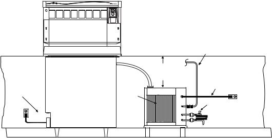
Installing Satellite-fill icemaker and rough-in utilities without optional slide-out accessory
The requirements below are for icemaker installation without the Follett slide-out accessory. These procedures ensure that the icemaker can be easily removed as one unit for cleaning and maintenance. For installation with the slide-out accessory, refer to instructions to install icemaker and rough-in utilities with optional slide-out accessory.
General requirements
Front of icemaker free of obstructions, plumbing lines, electric conduits.
12" (305mm) minimum clearance above icemaker for access to icemaker components.
6" (153mm) minimum clearance between exhaust side of icemaker and adjacent equipment. Do NOT weld icemaker to counter channels.
Large, removable panels in counter face to allow icemaker removal.
Machine stand accessory required for icemakers not supported on counter channels.
Connection requirements
Compression fittings for water and drain lines.
Separate drains for condenser and icemaker. Do NOT connect drains. 20 amp power supply with 6 feet.
|
|
bin signal from |
|
|
dispenser |
|
|
to icemaker |
|
|
12" |
|
|
305mm |
|
|
clearance |
|
|
separate power |
separate power |
front of |
to icemaker |
to dispenser |
icemaker |
|
|
clear |
|
|
|
water shut off |
|
|
compression fittings |
|
|
for water and drain lines |
Note: Diagram intended as guide only. All field wiring to be installed in accordance with NEC and local electrical codes.
8
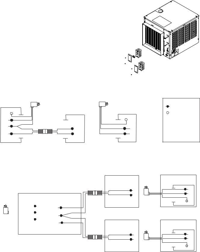
Field wiring diagrams for Satellite-fill icemaker installations
All field wiring must be installed in accordance with NEC and local electrical codes.
Field wiring diagram is intended only to aid electrician or technician in understanding how equipment works.
Should local codes require a hard-wired connection and/or shielded wiring, eliminate the cord and plug(s) and follow the appropriate field wiring diagram.
MCD400A/W and R400A/W icemakers have separate power supply from dispenser. Electric disconnects required within 10 ft (3m) for all hard-wired connections.
Recommended junction box preparation of hard-wired Satellite-fill icemakers.
1.Cut plugs from supplied power cords.
2.Replace upper (power) strain relief with a cord connector.
3.Mount two 2" x 4" junction boxes using supplied holes in icemaker face.
4.Make power and bin signal connections.
25, 50 or 110 ice and water dispenser with ONE Satellite-fill icemakers (dispenser models 25CR400A/W, 25HR400A/W, 50CR400A/W, 50HR400A/W, 110CR400A/W)
Dispenser junction box
GND GRN
X
B
W
R
Electric |
Electric |
power |
power |
source |
source |
Lower icemaker junction box (bin signal)
W
B
Upper icemaker junction box (power)
GND GRN
X
W
B
LEGEND
WIRENUT FIELD
CONNECTIONS
XEQUIPMENT GROUND
B BLACK
W WHITE
GRN GREEN
BL BLUE
Y YELLOW
RD RED
VU155/VU300 ice and beverage dispenser with either ONE or TWO Satellite-fill icemakers
Note: 24V bin signal;Verify black bin signal wire is on the 24V terminal
|
|
|
|
|
|
|
|
|
|
|
|
|
|
|
Icemaker #1 |
|
|
|
|
|||||
|
|
|
|
|
|
|
|
|
|
|
|
|
|
|
(optional) |
|
Electric |
|
|
|||||
|
|
|
|
|
|
|
|
|
|
|
|
|
|
|
Lower junction box |
|
Upper junction box |
|
||||||
|
|
|
|
|
|
|
|
|
|
|
|
|
|
|
|
power |
|
|||||||
|
|
|
|
|
|
|
|
|
|
|
|
|
|
|
(24V bin signal) |
|
(power) |
|
||||||
|
|
|
|
|
|
|
|
|
|
|
|
|
|
|
|
source |
|
|||||||
|
|
|
|
|
|
|
|
|
|
|
|
|
|
|
|
|
|
|
|
|
|
|
|
|
|
|
|
|
|
|
|
|
DISPENSER |
|
|
|
|
|
|
|
B |
|
|
W |
|||||
|
|
|
|
|
|
|
|
|
|
|
|
|
|
|
|
|
||||||||
|
|
|
|
|
|
|
|
|
|
|
|
|
|
|
|
|
B |
|||||||
Electric |
|
|
|
|
|
|
|
|
|
|
|
|
|
|
|
|
|
|
W |
|
|
|||
Left junction box |
|
Right junction box |
|
|
|
|
|
|
|
|
|
|
||||||||||||
power |
|
|
|
|
|
|
|
|
|
|
GND |
GRN |
||||||||||||
|
|
|
|
|
|
|
|
|
|
|||||||||||||||
source |
|
|
|
|
|
W |
|
|
|
|
|
|
|
|
|
|
|
|
|
|
X |
|||
|
|
|
|
|
|
|
|
|
|
|
|
|
|
|
|
|
|
|
||||||
|
|
|
|
|
|
|
|
|
BL |
|
|
|
|
|
|
|
|
|
|
|
||||
|
|
|
|
|
|
|
|
|
|
|
|
|
|
|
|
|
|
|
|
|||||
|
|
|
|
|
|
|
|
|
|
|
|
|
|
|
|
|
|
|
|
|||||
|
|
|
|
|
|
|
|
B |
|
Y |
|
Icemaker #2 |
|
|
|
|
||||||||
|
|
|
|
|
|
|
|
|
|
|
|
|
|
|||||||||||
|
|
|
|
|
|
|
|
|
|
|
|
|
|
|||||||||||
|
|
|
|
|
|
|
|
|
|
|
|
|
|
|
||||||||||
|
|
|
|
|
|
|
|
|
|
|
(optional) |
|
|
|
|
|||||||||
|
|
|
|
|
|
|
|
|
|
|
|
|
|
|
|
|
|
|
||||||
|
|
|
|
|
GND |
|
RD |
|
Lower junction box |
|
Electric |
Upper junction box |
|
|||||||||||
|
|
|
|
|
|
GRN |
|
|
|
|
|
|
(24V bin signal) |
|
power |
(power) |
|
|||||||
|
|
|
|
|
|
|
|
|
|
|
|
|
|
|
|
|
|
|
|
|
W |
source |
|
W |
|
|
|
|
|
|
|
|
|
|
|
|
|
|
|
|
|
|
|
|
|
|
|||
|
|
|
|
|
|
|
|
|
|
|
|
|
|
|
|
|
|
|
|
|
|
|
||
|
|
|
|
|
|
|
|
|
|
|
|
|
|
|
|
|
|
|
|
|
|
|
||
|
|
|
|
|
|
|
|
|
|
|
|
|
|
|
|
|
|
|
|
|
B |
|
|
B |
|
|
|
|
|
|
|
|
|
|
|
|
|
|
|
|
|
|
|
|
|
|
|
|
|
|
|
|
|
|
|
|
|
|
|
|
|
|
|
|
|
|
|
|
|
|
|
|
GND |
GRN |
|
|
|
|
|
|
|
|
|
|
|
|
|
|
|
|
|
|
|
|
|
|
|
||
|
|
|
|
|
|
|
|
|
|
|
|
|
|
|
|
|
|
|
|
|
|
|
X |
|
9
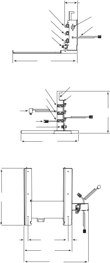
Installing Satellite-fill icemaker and rough-in utilities with optional slide-out accessory
The slide-out accessory allows the icemaker to be pulled out on a track from below a counter without disconnecting utilities. A leg supports the icemaker in the full-out position. If your order did not include a slide-out accessory proceed to icemaker ventilation and exhaust.
Step 1 – Installing track accessory (Follow either A or B below for Satellite-fill icemaker)
Track must be positioned flush against inside of counter and slightly above counter access opening.
A. When icemaker stand is used (required if icemaker is not supported on counter channels)
1.Bolt vertical utility panel to slide-out track assembly with supplied 10/32 screws.
2.Secure slide-out track assembly to icemaker stand with 10/32 screws provided.
3.Position icemaker stand in desired location and adjust stand legs to proper height and level in both directions.
4.Using holes in flanged legs as template, mark floor for 12 anchoring holes to be drilled.
5.Remove stand/track assembly and drill marked holes.
6.Reposition and anchor stand to floor with 12 fasteners appropriate to floor material (not supplied).
Stand MUST be anchored to avoid tipping and possible injury when icemaker is pulled out.
B. When icemaker is supported on counter channels
1.Bolt vertical utility panel to slide-out track assembly with supplied 10/32 screws.
2.Position track assembly on counter channels (Fig. 3).
3.Using holes in track assembly as a template, mark and drill required holes in counter channels.
4.Remove track assembly on channels and drill marked holes.
5.Reposition track assembly on channels and secure using appropriate hardware (not supplied).
14"
(356mm)
verical utility panel
13"
(331mm)
12.75
14"
(324mm)
(356mm)
slide-out-track
10
Step 2 – Installing Satellite-fill icemaker on slide-out track
A. When icemaker is shipped with slide-out track accessory (follow either A or B)
1.Connect inlet water, drain, and power supply to back of vertical utility panel.
2.Place icemaker on slide-out track assembly.
3.Connect drain and water lines.
4.Connect electrical plugs from icemaker to utility panel.
B. When icemaker is installed in and shipped with counter
1.Remove two outer rear screws from icemaker and install supplied spacer and screw (Fig. 3).
2.Place icemaker on slide-out track assembly.
3.Connect drain and water lines.
4.Connect electrical plug from icemaker to utility panel.
5.Remove pin from adjustable leg.
6.Place hold-down strap over leg block and secure strap to slide-out assembly with supplied screws (Fig. 4).
7.Reinstall pin in leg block.
8.At job site remove hold-down strap and make utility connections at rear utility panel.
counter front 
grille supplied with aircooled satellite-fill icemakes
bin signal cord (icemaker connection) 
air in (air-cooled units only)
position track accessory so that 2" (51mm) duct supplied with air-cooled satellite-fill icemaker mates with back of counter opening.
power cord
 bin signal cord
Fig. 3
|
|
Remove screw. Install |
Fig. 4 |
hold-down strap |
supplied screws and spacers. |
|
||
(for installation; remove |
|
|
|
|
|
|
and discard) |
|
supplied screws (for installation; remove and discard)
11
Front view
3/8" OD push-in condenser inlet |
5.25" |
|
(134mm) |
||
(water-cooled only) |
||
|
||
3/8" OD push-in condenser drain |
icemaker |
|
(water-cooled only) |
power outlet |
|
|
icemaker |
|
3/8" OD push-in icemaker water inlet |
twist-lock |
|
barbed push-on icemaker drain |
bin signal cord |
|
|
25.875"
(658mm)
Side view
(All customer field |
|
|
connections are made |
|
|
to rear of vertical |
3/8" OD push-in condenser inlet |
|
utility panel) |
(water-cooled only) |
cord holder |
|
3/8" OD push-in condenser drain |
vertical utility panel |
|
(water-cooled only) |
|
|
|
|
|
3/8" OD push-in icemaker water inlet |
|
|
icemaker power cord |
16.75" |
|
bin signal cord connector |
(415mm) |
|
|
|
|
(to connect to dispenser bin signal cord) |
|
|
3/4" MPT icemaker drain |
|
|
22.75" |
|
|
(578mm) |
|
Plan view
22.75"
(578mm)
|
Icemaker front |
|
|
1.563" |
16" |
1.563" |
|
(40mm) |
(407mm) |
||
(40mm) |
|||
|
|
||
|
19.25" |
|
|
|
(489mm) |
|
|
|
25.875" |
|
|
|
(658mm) |
|
12
 Loading...