


 25 and 50 Series
Ice and Water Dispensers
Order parts online www.follettice.com
Installation, Operation and Service Manual
|
25CT400A/W |
50CT400A/W |
|
|
|
25HT400A/W |
50HT400A/W |
||||||||||||||||||||||
|
(shown with SensorSAFE™ accessory) |
|
|
|
(shown with SensorSAFE accessory) |
||||||||||||||||||||||||
|
|
|
|
|
|
|
|
|
|
|
|
|
|
|
|
|
|
|
|
|
|
|
|
|
|
|
|
|
|
|
|
|
|
|
|
|
|
|
|
|
|
|
|
|
|
|
|
|
|
|
|
|
|
|
|
|
|
|
|
|
|
|
|
|
|
|
|
|
|
|
|
|
|
|
|
|
|
|
|
|
|
|
|
|
|
|
|
|
|
|
|
|
|
|
|
|
|
|
|
|
|
|
|
|
|
|
|
|
|
|
|
|
|
|
|
|
|
|
|
|
|
|
|
|
|
|
|
|
|
|
|
|
|
|
|
|
|
|
|
|
|
|
|
|
|
|
|
|
|
|
|
|
|
|
|
|
|
|
|
|
|
|
|
|
|
|
|
|
|
|
|
|
|
|
|
|
|
|
|
|
|
|
|
|
|
|
|
|
|
|
|
|
|
|
|
|
|
|
|
|
|
|
|
|
|
|
|
|
|
|
|
|
|
|
|
|
|
|
|
|
|
|
|
|
|
|
|
|
|
|
|
|
|
|
|
|
|
|
|
|
|
|
|
|
|
|
|
|
|
|
|
|
|
|
|
|
|
|
|
|
|
|
|
|
|
|
|
|
|
|
|
|
|
|
|
|
|
|
|
|
|
|
|
|
|
|
|
|
|
|
|
|
|
|
|
|
|
|
|
|
|
|
|
|
|
|
|
|
|
|
|
|
|
|
|
|
|
|
|
|
|
|
|
|
|
|
|
|
|
|
|
|
|
|
|
|
|
|
|
|
|
|
|
|
|
|
|
|
|
|
|
|
|
|
|
|
|
|
|
|
|
|
|
|
|
|
|
|
|
|
|
|
|
|
|
|
|
|
|
|
|
|
|
|
|
|
|
|
|
|
|
|
|
|
|
|
|
|
|
|
|
|
|
|
|
|
|
|
|
|
|
|
|
|
|
|
|
|
|
|
|
|
|
|
|
|
|
|
|
|
|
|
|
|
|
|
|
|
|
|
|
|
|
|
|
|
|
|
|
|
|
|
|
|
|
|
|
|
|
|
|
|
|
|
|
|
|
|
|
|
|
|
|
|
|
|
|
|
|
|
|
|
|
|
|
|
|
|
|
|
|
|
|
|
|
|
|
|
|
|
|
|
|
|
|
|
|
|
|
|
|
|
|
|
|
|
|
|
|
|
|
|
|
|
|
|
|
|
|
|
|
|
|
|
|
|
|
|
|
|
|
|
|
|
|
|
|
|
|
|
|
|
|
|
|
|
|
|
|
|
|
|
|
|
|
|
|
|
|
|
|
|
|
|
|
|
|
|
|
|
|
|
|
|
|
|
|
|
|
|
|
|
|
|
|
|
|
|
|
|
|
|
|
|
|
|
|
|
|
|
|
|
|
|
|
|
|
|
|
|
|
|
|
|
|
|
|
|
|
|
|
|
|
|
|
|
|
|
|
|
|
|
|
|
|
|
|
|
|
|
|
|
|
|
|
|
|
|
|
|
|
|
|
|
|
|
|
|
|
|
|
|
|
|
|
|
|
|
|
|
|
|
|
|
|
|
|
|
|
|
|
|
|
|
|
|
|
|
|
|
|
|
|
|
|
|
|
|
|
|
|
|
|
|
|
|
|
|
|
|
|
|
|
|
|
|
|
|
|
|
|
|
|
|
|
|
|
|
|
|
|
|
|
|
|
|
|
|
|
|
|
|
|
|
|
|
|
|
|
|
|
|
|
|
|
|
|
|
|
|
|
|
|
|
|
|
|
|
|
|
|
|
|
|
|
|
|
|
|
|
|
|
|
|
|
|
|
|
|
|
|
|
|
|
|
|
|
|
|
|
|
|
|
|
|
|
|
|
|
|
|
|
|
|
|
|
|
|
|
|
|
|
|
|
|
|
|
|
|
|
|
|
|
|
|
|
|
|
|
|
|
|
|
|
|
|
|
|
|
|
|
|
|
|
|
|
|
|
|
|
|
|
|
|
|
|
|
|
|
|
|
|
|
|
|
|
|
|
|
|
|
|
|
|
|
|
|
|
|
|
|
|
|
|
|
|
|
|
|
|
|
|
|
|
|
|
|
|
|
|
|
|
|
|
|
|
|
|
|
|
|
|
|
|
|
|
|
|
|
|
|
|
|
|
|
|
|
|
|
|
|
|
|
|
|
|
|
|
|
|
|
|
|
|
|
|
|
|
|
|
|
|
|
|
|
|
|
|
|
|
|
|
|
|
|
|
|
|
|
|
|
|
|
|
|
|
|
|
|
|
|
|
|
|
|
|
|
|
|
|
|
|
|
|
|
|
|
|
|
|
|
|
|
|
|
|
|
|
|
|
|
|
|
|
|
|
|
|
|
|
|
|
|
|
|
|
|
|
|
|
|
|
|
|
|
|
|
|
|
|
|
|
|
|
|
|
|
|
|
|
|
|
|
|
|
|
|
|
|
|
|
|
|
|
|
|
|
|
|
|
|
|
|
|
|
|
|
|
|
|
|
|
|
|
|
|
|
|
|
|
|
|
|
|
|
|
|
|
|
|
|
|
|
|
|
|
|
|
|
|
|
|
|
|
|
|
|
|
|
|
|
|
|
|
|
|
|
|
|
|
|
|
|
|
|
|
|
|
|
|
|
|
|
|
|
|
|
|
|
|
|
|
|
|
|
|
|
|
|
|
|
|
|
|
|
|
|
|
|
|
|
|
|
|
|
|
|
|
|
|
|
|
|
|
|
|
|
|
|
|
|
|
|
|
|
|
|
|
|
|
|
|
|
|
|
|
|
|
|
|
|
|
|
|
|
|
|
|
|
|
|
|
|
|
|
|
|
|
|
|
|
|
|
|
|
|
|
|
|
|
|
|
|
|
|
|
|
|
|
|
|
|
|
|
|
|
|
|
|
|
|
|
|
|
|
|
|
|
|
|
|
|
|
|
|
|
|
|
|
|
|
|
|
|
|
|
|
|
|
|
|
|
|
|
|
|
|
|
|
25CR400A/W 50CR400A/W |
25HR400A/W 50HR400A/W |
25FB400A/W |
50FB400A/W |
(shown with SensorSAFE accessory)
Following installation, please forward this manual to the appropriate operations person.
801 Church Lane • Easton, PA 18040, USA |
|
Toll free (800) 523-9361 • (610) 252-7301 |
|
Fax (610) 250-0696 • www.follettice.com |
208596R07 |

Table of contents
Before you begin |
3 |
Specifications |
4 |
Field wiring |
5 |
Installation |
7 |
Installing freestanding dispensers |
7 |
Installing countertop dispensers |
9 |
Installing wall mount dispensers |
11 |
Installing Satellite-fill™ icemakers |
13 |
Installing top mount icemakers |
14 |
User information |
16 |
Cleaning and sanitizing procedures |
16 |
Service Information |
18 |
Wiring diagram – lever models |
18 |
Wiring diagram – SensorSAFE models |
19 |
Dispenser troubleshooting |
20 |
Troubleshooting SensorSAFE board and sensors |
21 |
Disassembly and replacement instructions |
23 |
Thermostat locations |
25 |
Parts |
26 |
Dispenser exterior |
26 |
Dispense chute and splash panel areas – lever models |
27 |
Electrical box – lever models |
27 |
Dispense chute and splash panel areas – SensorSAFE models |
28 |
Electrical box – SensorSAFE models |
29 |
Wheel motor and drive system |
29 |
Hopper components |
30 |
Chilled water components |
31 |
Countertop dispenser plumbing connections |
32 |
Follett Corporation
Equipment Return Policy
Follett equipment may be returned for credit under the following conditions:
1.The equipment is new and unused.
2.A return authorization number has been issued by customer service within 30 days after shipment.
3.Follett receives the equipment at the factory in Easton, PA within 30 days after issuance of the return authorization number.
4.The equipment must be returned in Follett packaging. If the packaging has been damaged or discarded, Follett will forward, at the customer’s expense, new packaging.
Note: Return freight charges are the responsibility of the customer. If equipment is returned and is damaged because of improper packaging, Follett Corporation will not be held responsible.
Credit will be issued when:
The equipment has been inspected by Follett and deemed suitable to be returned to stock.
Note: A 15% restocking charge will be deducted from the credit. If the cost to return the product to stock exceeds 15%, the actual cost will be deducted.
2
Welcome to Follett
Follett equipment enjoys a well-deserved reputation for excellent performance, long-term reliability and outstanding after-the-sale support. To ensure that this equipment delivers that same degree of service, we ask that you review the installation portion of this manual before beginning to install the unit. Our installation instructions are designed to help you achieve a trouble-free installation. Should you have any questions or require technical help at any time, please call our technical service group toll free at (800) 523-9361 or (610) 252-7301.
Before you begin
After uncrating and removing all packing material, inspect the equipment for concealed shipping damage. If damage is found, notify your shipper immediately and contact Follett Corporation for help in filing a claim, if necessary.
Check your paperwork to determine which model you have. Follett model numbers are designed to provide information about the type and capacity of Follett equipment. Following is an explanation of model numbers:
50CT400A
Condenser type – A = air-cooled, W = water-cooled
Icemaker capacity and refrigerant – 400 = 400 lbs (181kg)/day, R404A refrigerant
Icemaker location – R = Satellite-fill icemaker, T = integral icemaker in top of cabinet,
B = icemaker in base of freestanding units
Dispenser configuration – C = countertop, H = wall mount, F = freestanding
Approximate storage capacity in lbs
!Important cautions
•Do not tilt any unit further than 30° off vertical during uncrating or installation
•Dispenser bin area contains mechanical, moving parts. Keep hands and arms clear of this area at all times. If access to this area is required, power to unit must be disconnected first.
•Follett recommends a Follett QC4-FL4S water filter system (item# 00130299) be installed in the icemaker inlet water line
•Prior to operation clean and sanitize the dispenser in accordance with instructions found in this manual
•Ice is slippery. Be sure counters and floors around dispenser are clean, dry and free of ice.
3
Specifications
Electrical
1.Models with Satellite-fill icemakers (25CR400A/W, 50CR400A/W, 25HR400A/W, 50HR400A/W)
|
Icemaker |
Max. fuse |
Dispenser |
Max. fuse |
Basic electrical: 115V/60Hz/1 phase |
11.0 amps |
20 amps |
4.0 amps |
20 amps |
2.Freestanding models and models with integral icemakers (25FB400A/W, 50FB400A/W, 25CT400A/W, 50CT400A/W, 25HT400A/W, 50HT400A/W)
|
Total system |
Max. fuse |
Basic electrical: 115V/60Hz/1 phase |
14.0 amps |
20 amps |
3.Dispensers and Satellite-fill icemakers are supplied with 7-foot power cord with NEMA 5-20 hospital grade plug. Connect to 20 amp circuit fuse or breaker.
Note: It is preferred that circuit be protected by a GFCI.
Ambient
Air temp |
100° F/38°C max. |
50°F/10°C min. (best performance below 80˚F/27˚C) |
Water temp |
90°F/32°C max. |
40°F/4°C min. (best performance below 70˚F/21˚C) |
Water pressure |
70 P.S.I. max. |
10 P.S.I. min. |
Plumbing
|
25/50 CR with |
25/50 HR with |
25/50 CT with |
25/50 HT with |
25/50 FB |
|
Satellite-fill |
Satellite-fill |
integral |
integral |
icemaker |
|
icemaker |
icemaker |
icemaker |
icemaker |
in base |
Dispenser drain |
3/4" FPT |
3/4" ID tubing |
3/4" FPT |
3/4" ID tubing |
3/4" FPT |
Icemaker drain |
3/4" MPT |
3/4 MPT |
– |
– |
3/4" MPT |
Dispenser water inlet |
3/8" FPT |
3/8" FPT |
3/8" FPT |
3/8" FPT |
3/8" FPT |
Satellite-fill IM water inlet |
3/8" OD push-in |
3/8" OD push-in |
– |
– |
– |
Cond. inlet – w/c only |
3/8" FPT |
3/8" FPT |
3/8" FPT |
3/8" FPT |
3/8" FPT |
Cond. drain – w/c only |
3/8" FPT |
3/8" FPT |
3/8" FPT |
3/8" FPT |
3/8" FPT |
Note: Water shut-off recommended within 10 feet (3m) of dispenser. Drain to be hard piped and insulated, and maintain slope of at least 1/4" per foot (6mm per 30.4cm run) of slope. All plumbing connections must be made in accordance with local building codes.
Ventilation clearances
Countertop and wall mount models with Satellite-fill icemaker (25CR400A/W, 50CR400A/W, 25HR400A/W, 50HR400A/W) — none. 12" (305mm) at top advised for service.
Countertop and wall mount models with integral icemaker (25CT400A/W, 50CT400A/W, 25HT400A/W, 50HT400A/W) — 6" (153mm) at top. 6" (153mm) each side advised for service.
Freestanding models (25FB400A/W, 50FB400A/W) — 4" (102mm) at rear. 12" (305mm) at top advised for service.
4
Field wiring for countertop and wall mount dispensers with Satellite-fill icemakers
!diagram is intended only to aid electrician or technician in understanding how equipment works.All field wiring must be installed in accordance with NEC and local electrical codes. Field wiring
Model |
Electrical connection |
Circuits required |
|
|
|
25FB400A/W, 50FB400A/W |
cord & plug provided |
115/60/1, 20 amp max. fuse size |
25CT400A/W, 50CT400A/W |
cord & plug provided |
115/60/1, 20 amp max. fuse size |
25HT400A/W, 50HT400A/W |
|
|
25CR400A/W, 50CR400A/W |
cord & plug provided |
115/60/1 |
25HR400A/W, 50 HR400A/W |
|
dispenser: 20 amp max. fuse size |
|
|
ice maker: 20 amp max. fuse size |
|
|
|
!cord and plug(s) and follow the appropriate field wiring diagram on the following page.
See Icemaker Installation and Operation manual for recommended junction box preparation of hard- wired Satellite-fill icemakers.Attention – Should local codes require a hard-wired connection and/or shielded wiring, eliminate the
5
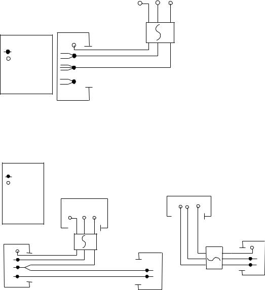
Field Wiring diagrams
(For installations requiring hard-wiring equipment)
Freestanding dispensers, countertop and wall mount dispensers with integral icemakers
IMPORTANT |
|
Electric Power Source |
||||
FIELD WIRING DIAGRAM IS |
|
|
|
|
|
Standard electrical - 115V, 1 Ph, 60 Hz, |
|
|
|
|
|
max. fuse size 20 amps |
|
INTENDED TO AID ELECTRICIAN |
|
|
|
|
|
|
|
|
|
|
|
|
|
OR TECHNICIAN IN UNDERSTANDING |
|
|
|
|
|
|
HOW EQUIPMENT WORKS. ALL FIELD |
|
GND |
B W |
|
||
WIRING MUST BE INSTALLED IN |
|
|
X |
|
|
|
ACCORDANCE WITH NEC AND LOCAL |
|
|
|
|
|
|
|
GRN |
|
|
|
||
ELECTRICAL CODES. |
|
|
|
|
||
|
|
|
|
|
|
|
|
|
|
|
|
||
|
|
|
|
|
|
|
|
|
|
|
|
|
|
|
|
|
|
|
|
|
DISPENSER
JUNCTION BOX FUSED
DISCONNECT
|
LEGEND |
GND X |
GRN |
|
|
||
|
WIRENUT |
|
B |
|
|
|
|
X |
EQUIPMENT |
|
|
|
GROUND |
|
W |
B - BLACK |
|
|
|
W - WHITE |
|
R |
|
R - RED |
|
||
|
|
||
GRN - GREEN |
|
|
|
Countertop and wall mount dispensers with Satellite-fill icemakers
LEGEND
WIRENUT
XEQUIPMENT GROUND
B - BLACK
W - WHITE
R - RED
GRN - GREEN
DISPENSER JUNCTION BOX
GND X GRN
B
W
R
|
IMPORTANT |
Standard electric - 115V, 60 Hz, 1 Ph, |
FIELD WIRING DIAGRAM IS INTENDED TO AID ELECTRICIAN |
OR TECHNICIAN IN UNDERSTANDING HOW EQUIPMENT WORKS. |
|
Max. fuse size per circuit - 20 amps |
ALL FIELD WIRING MUST BE INSTALLED IN ACCORDANCE WITH |
|
NEC AND LOCAL ELECTRICAL CODES. |
|
|
Electric Power Source |
Electric Power Source |
|
|
|
B W |
GND |
|
|
|
|
X |
|
|
B W |
|
GRN |
|
GND |
|
|
|
|
X |
|
|
|
|
GRN |
|
|
|
|
|
|
|
|
UPPER ICEMAKER |
|
|
|
|
JUNCTION BOX |
|
FUSED |
|
FUSED |
(POWER) |
|
LOWER ICEMAKER |
|
||
|
DISCONNECT |
|
||
|
DISCONNECT |
GND GRN |
||
|
JUNCTION BOX |
|
||
|
|
|
||
|
|
(BIN SIGNAL) |
|
X |
|
|
|
|
|
|
|
|
|
W |
|
|
|
|
B |
|
|
W |
|
|
|
|
B |
|
|
6

Installation procedure
Before you begin
•All dispensers must be installed level in both directions to ensure proper operation
•Required ventilation and recommended service clearances:
•Countertop and wall mount models with Satellite-fill icemaker (25CR400A/W, 25HR400A/W, 50CR400A/W, 50HR400A/W)
— none. 12" (305mm) at top recommended for service
•Countertop and wall mount models with integral icemaker (25CT400A/W, 25HT400A/W, 50CT400A/W, 50HT400A/W) — 6" (153mm) at top. 6" (153mm) each side recommended for service
•Freestanding models (25FB400A/W, 50FB400A/W) — 4" (102mm) at rear. 12" (305mm) at top recommended for service
•All countertop dispensers provide the option of taking utilities out the bottom or back of the dispenser.
See counter cut-out on page 9 (Fig. 2) for bottom exiting utilities on units with and without drain pans. For installations where utilities will exit through back of dispenser, refer to back view drawings.
•Wall mount models are designed for use above sinks or custom drain pans, and are not normally equipped with integral drain pans. Front of sink should be a minimum of 23" (584mm) from back wall. Connection of utilities through the back for wall mount units is the same as shown in drawings for countertop models except that the drain pan is absent.
•SensorSAFE dispensers are shipped with a plastic, protective film on sensor lenses. For proper operation, plastic film must be removed after installation.
Installing freestanding dispensers
1.Carefully tip dispenser back to expose underside and block up in place.
!Do not tilt unit further than 30° off vertical.
2.Remove legs from shipping box (taped to drain pan of dispenser) and screw into dispenser bottom, taking care to seat legs securely against underside of dispenser.
3.Position dispenser in desired location and adjust legs to level in both directions.
4.Connect water supply to 3/8" FPT fitting on back of dispenser (Fig. 1A).
5.Remove 3/4" dispenser drain line plug from back of unit and discard. Connect separate drain lines to 3/4" FPT dispenser drain fitting (Fig.1B), and 3/4" MPT icemaker drain fitting (Fig. 1C) on back of dispenser.
6.Run drain lines to wall or floor drain. Provide an air break between the drain lines and drain. If icemaker drain fitting is below an intended wall drain, a condensate pump must be used.
7.If icemaker is a water-cooled unit, connect water-cooled condenser supply line to 3/8" FPT condenser inlet fitting on back of dispenser (Fig.1D).
Note: Do not run condenser supply water through icemaker water filter system.
8.Connect condenser drain line to 3/8" FPT condenser outlet fitting on back of dispenser (Fig.1E).
Important: Do not connect condenser drain line to any other drain lines.
9.Plug dispenser into 20 amp rated NEMA 5-20 wall socket.
10.Remove front cover of base section by removing two screws at bottom corners of cover. Allow cover to drop approximately 3/8" (5mm) and pull forward.
11.Turn on water supply and check that water level in float reservoir (when full) is within 1/4" (6mm) of mark on side of reservoir, and that float moves freely. Check for leaks.
7
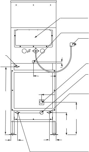
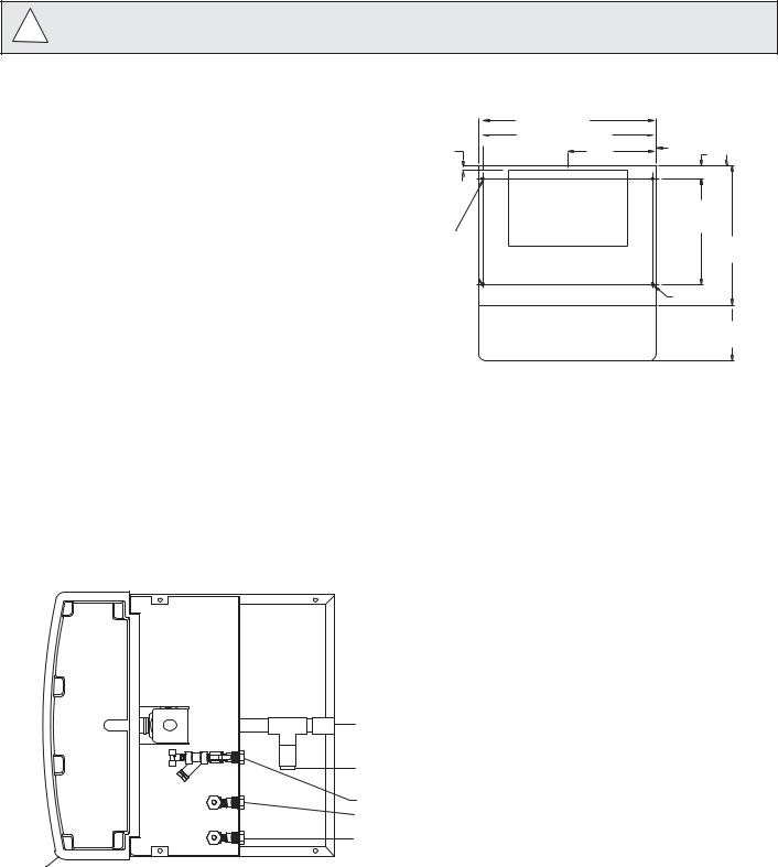
Fig. 1 – Rear connections, freestanding models
.8"
(A) 3/8" FPT 
 (20mm)
water inlet
10.5"
(267mm)
6.75" 31.5" (171mm)
(800mm)
15.125"
(384mm)
10.25"
(259mm)
3.125" |
3.125" |
(79mm) |
(79mm) |
access panel
(B) 3/4" FPT drain
power cord
(D)3/8" FPT condenser inlet location (water-cooled only)
(E)3/8" FPT condenser outlet location (water-cooled only)
(C)3/4" MPT icemaker drain location (water-cooled only)
(B) 3/4" MPT icemaker drain location (air-cooled only)
12 Verify that water sensor tabs are immersed in water in reservoir.
13.Remove top front cover by removing two screws at bottom corners of cover. Lift cover slightly and pull forward.
14.If dispenser is equipped with SensorSAFE remove protective plastic coating from dispense sensor labels.
15.Turn on dispenser power and bin signal rocker switches. Check dispenser and icemaker operation.
16.Sanitize icemaker according to instructions in icemaker manual. Discard ice made during sanitizing process.
17.Turn off icemaker bin signal switch.
18.Remove dispenser hopper lid; clean and sanitize dispenser according to instructions beginning on page 16.
19.Turn icemaker bin signal switch on and replace front covers, securing with screws.
8
Installing countertop dispensers
Dispensers with top mount icemakers cannot be mounted on legs. They must be bolted to counter. ! Use gloves when lifting icemaker to protect hands from sheet metal edges.
1.Position dispenser in desired location, mark dispenser outline on counter and remove dispenser.
2.Drill four 3/8" (5mm) holes in counter (Fig. 2) to anchor dispenser to counter.
Follett countertop dispensers can have any or all utilities run directly through counter or out rear of dispenser. For dispensers with any utilities exiting through counter, make counter cut-out (Fig. 2)
3.If ice transport tube will exit out rear of dispenser, remove ice transport tube knock-out (Fig. 5G) from rear of dispenser.
Note: Utility connections can be accessed through front of dispenser by removing stainless steel splash panel, or by removing access panel (Figs. 4, 5) on back of dispenser.
4.If any electric utilities or water line will be connected through rear of dispenser, remove utility knock-out (Figs. 4, 5F) from rear of dispenser and install supplied protective grommet.
Fig. 2 – Counter cut-out, all models
|
21" (533mm) |
|
|
|
20.125" (511mm) |
.44" (11mm) |
|
.5" |
10.5" |
||
1.5" (38mm) |
|||
(127mm) |
(267mm) |
||
|
|||
|
|
||
|
cut-out |
|
|
.375" holes |
9" X 14" |
12.5" |
|
(227mm x 356mm) |
(317mm) |
||
(9.52mm) |
|
16.5" |
|
|
|
||
|
|
(419mm) |
|
|
|
.375 (10mm) |
|
|
drain pan |
6.5" |
|
|
(165mm) |
||
|
|
Fig. 3 – Top view, dispenser plumbing connections countertop
(L) 3/4" FPT dispenser drain
(K) alternate 3/4" dispenser (drain location)
(G) 3/8" FPT water inlet
(J) 3/8" FPT condenser water outlet
(H) 3/8" FPT condenser water inlet
drain pan
9
5.If power is to be supplied through counter cut-out, complete steps 6-9. If power is to be supplied through rear of dispenser, proceed to step 10.
6.Temporarily remove rear access panel (Figs. 4 and 5) from rear of dispenser.
7.Loosen junction box mounting screws. Lift junction box and power cord up until cord and mounting screws clear notches on rear panel of dispenser. Remove Phillips head screws from right side of junction box.
8.Rotate junction box 90 degrees so that screw holes on right side of junction box align with holes on rear dispenser panel. Resecure junction box to dispenser using Phillips head screws.
9.Place power cord inside dispenser and replace access panel (Figs. 4, 5) to rear of dispenser.
Note: For dispensers to be installed with utilities connected through rear of dispenser, it may be easier to make preliminary connections before dispenser is set in place.
10.Apply a thick bead, approximately. 1/4" (6mm) diameter, of NSF listed silicone sealant (Dow-Corning RTV732 or equivalent) 1/4" (6mm) inside marked outline of dispenser.
11.Carefully position dispenser on counter.
12.Remove four screws securing splash panel to front of dispenser and gently lay splash panel on counter. (Water line to solenoid valve can be disconnected from water inlet valve by pushing on ring at end of inlet fitting while pulling on tubing.)
13.Secure dispenser to counter with four 3/8" bolts (supplied by others).
14.Smooth excess sealant around outside of dispenser.
15.Run water supply line from back of dispenser through utility knock-out (Figs. 4, 5F) or up through counter cut-out. Connect water supply line to 3/8" FPT fitting on (Fig. 3G) utility flange at bottom of dispenser.
16.Remove 3/4" drain connection plug from either fitting at rear of dispenser (Fig. 3L) or internal fitting
(Fig. 3K), as appropriate. Connect and run a dedicated drain line to wall or floor drain. An air break should be provided.
17.Proceed with either Satellite-fill or top-mounted icemaker connection instructions, as appropriate.
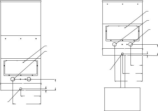
Fig. 4 – Rear connections, countertop models with integral icemakers
|
access panel |
|
(F) utility connection |
|
knock-out |
|
5.875" |
|
(149mm) |
10.5" |
.8" |
(267mm) |
(20mm) |
|
3/4" FPT drain |
14.75" |
|
|
|
(375mm) |
Fig. 5 – Rear connections, countertop models with Satellite-fill icemakers
access panel
(F) utility connection knock-out
(G) ice transport tube knock-out
5.875"
(149mm)
|
.8" |
6.375" |
(20mm) |
|
|
(162mm) |
|
3/4" FPT drain |
|
10.5" |
|
(267mm) |
|
14.75" |
|
(375mm) |
|
10
 Loading...