


Ti20
Table of contents
 Loading...
®
Ti20
Thermal Imager
Users Manual
January 2006
© 2006 Fluke Corporation, All rights reserved.
All product names are trademarks of their respective companies.

LIMITED WARRANTY AND LIMITATION OF LIABILITY
Each Fluke product is warranted to be free from defects in material and workmanship under normal use and
service. The warranty period is one year and begins on the date of shipment. Parts, product repairs, and
services are warranted for 90 days. This warranty extends only to the original buyer or end-user customer of
a Fluke authorized reseller, and does not apply to fuses, disposable batteries, or to any product which, in
Fluke's opinion, has been misused, altered, neglected, contaminated, or damaged by accident or abnor mal
conditions of operation or handling. Fluke warrants that software will operate substantially in accordance
with its functional specifications for 90 days and that it has been properly recorded on non-defective media.
Fluke does not warrant that software will be error free or operate without interruption.
Fluke authorized resellers shall extend this warranty on new and unused products to end-user customers
only but have no authority to extend a greater or different warranty on behalf of Fluke. Warranty support is
available only if product is purchased through a Fluke authorized sales outlet or Buyer has paid the
applicable international price. Fluke reserves the right to invoice Buyer for importation costs of
repair/replacement parts when product purchased in one country is submitted for repair in another country.
Fluke's warranty obligation is limited, at Fluke's option, to refund of the purchase price, free of charge repair,
or replacement of a defective product which is returned to a Fluke authorized service center within the
warranty period.
To obtain warranty service, contact your nearest Fluke authorized service center to obtain return
authorization information, then send the product to that service center, with a description of the difficulty,
postage and insurance prepaid (FOB Destination). Fluke assumes no risk for damage in transit. Following
warranty repair, the product will be returned to Buyer, transportation prepaid (FOB Destination). If Fluke
determines that failure was caused by neglect, misuse, contamination, alteration, accident, or abnormal
condition of operation or handling, including overvoltage failures caused by use outside the product’s
specified rating, or normal wear and tear of mechanical components, Fluke will provide an estimate of repair
costs and obtain authorization before commencing the work. Following repair, the product will be returned to
the Buyer transportation prepaid and the Buyer will be billed for the repair and return transportation charges
(FOB Shipping Point).
THIS WARRANTY IS BUYER'S SOLE AND EXCLUSIVE REMEDY AND IS IN LIEU OF ALL OTHER
WARRANTIES, EXPRESS OR IMPLIED, INCLUDING BUT NOT LIMITED TO ANY IMPLIED WARRANTY
OF MERCHANTABILITY OR FITNESS FOR A PARTICULAR PURPOSE. FLUKE SHALL NOT BE LIABLE
FOR ANY SPECIAL, INDIRECT, INCIDENTAL, OR CONSEQUENTIAL DAMAGES OR LOSSES,
INCLUDING LOSS OF DATA, ARISING FROM ANY CAUSE OR THEORY.
Since some countries or states do not allow limitation of the term of an implied warranty, or exclusion or
limitation of incidental or consequential damages, the limitations and exclu sions of this warranty may not
apply to every buyer. If any provision of this Warranty is held invalid or unenforceable by a court or other
decision-maker of competent jurisdiction, such holding will not affect the validity or enforceability of any other
provision.
Fluke Corporation
P.O. Box 9090
Everett, WA 98206-9090
U.S.A.
Fluke Europe B.V.
P.O. Box 1186
5602 BD Eindhoven
The Netherlands
11/99

Table of Contents
Chapter Title Page
1 Getting Started .................................................................................... 1-1
Introduction........................................................................................................ 1-1
Contacting Fluke................................................................................................ 1-1
Safety Information ............................................................................................. 1-2
Laser Warning Labels........................................................................................ 1-3
Unpacking the Imager........................................................................................ 1-4
Features and Controls ........................................................................................ 1-6
Operating the Controls....................................................................................... 1-7
Focusing the Imager ...................................................................................... 1-7
Understanding the Trigger............................................................................. 1-8
Using the AC Power Adapter ............................................................................ 1-9
Charging and Replacing the Batteries................................................................ 1-10
Using the Battery Charger ............................................................................. 1-10
Installing or Replacing the Batteries ............................................................. 1-11
Attaching the Wrist Strap .................................................................................. 1-12
Inputs and Connections...................................................................................... 1-13
Connecting the USB Cable............................................................................ 1-13
Mounting the Imager on a Tripod.................................................................. 1-14
Cleaning............................................................................................................. 1-14
Cleaning the Case .......................................................................................... 1-14
Cleaning the Lens .......................................................................................... 1-15
2 Basic Operation................................................................................... 2-1
Turning the Imager On and Off ......................................................................... 2-1
Understanding the Home Display...................................................................... 2-2
Aiming and Activating the Laser....................................................................... 2-4
Capturing Images............................................................................................... 2-5
Comparing Frozen Images to Stored Images..................................................... 2-5
Adjusting the Backlight ..................................................................................... 2-6
Setting the Temperature Scale ........................................................................... 2-7
Setting the Level ................................................................................................ 2-7
Adjusting the Span............................................................................................. 2-9
Manually Activating the Calibration Flag ......................................................... 2-9
Using Distance to Spot Size Ratio (D:S) ........................................................... 2-9
i

Ti20
Users Manual
Environmental Conditions ................................................................................. 2-11
Ambient Temperature Derating and Thermal Shock......................................... 2-11
Emissivity .......................................................................................................... 2-12
Reflected Temperature Compensation............................................................... 2-13
3 Advanced Imager Operation............................................................... 3-1
Data Management and Storage .......................................................................... 3-1
Viewing Stored Images ................................................................................. 3-1
Deleting Images............................................................................................. 3-2
Selecting a Palette.............................................................................................. 3-3
Adjusting Emissivity.......................................................................................... 3-4
Adjusting Reflected Temperature Compensation Values.................................. 3-6
Setting Alarm Limits ......................................................................................... 3-7
Adjusting Sleep Mode ....................................................................................... 3-9
Appendices
A Glossary....................................................................................................... A-1
B Basics of Infrared Measurement.................................................................. B-1
C Typical Emissivity Values........................................................................... C-1
D Specifications .............................................................................................. D-1
ii

List of Tables
Table Title Page
1-1. Symbols.................................................................................................................. 1-2
1-1. Standard Accessories ............................................................................................. 1-5
1-3. Features and Controls............................................................................................. 1-7
2-1. Contents of the Home Display ............................................................................... 2-3
C-1. Emissivity Values for Metals ................................................................................. C-2
C-2. Emissivity Values for Non-Metals......................................................................... C-4
iii

Ti20
Users Manual
iv

List of Figures
Figure Title Page
1-1. Laser Warning Labels ............................................................................................ 1-3
1-2. Standard Accessories ............................................................................................. 1-4
1-3. Ti20 Thermal Imager Features and Controls ......................................................... 1-6
1-4. Focusing the Imager............................................................................................... 1-8
1-5. Using the AC Power Adapter................................................................................. 1-9
1-6. Using the Battery Charger...................................................................................... 1-10
1-7. Replacing the Battery Pack .................................................................................... 1-11
1-8. Attaching the Wrist Strap....................................................................................... 1-12
1-9. Connecting Using the USB Cable.......................................................................... 1-13
1-10. Mounting the Imager on a Tripod .......................................................................... 1-14
2-1. Imager Splash Screen............................................................................................. 2-1
2-2. Imager home Display Zones .................................................................................. 2-2
2-3. Relationship Between FOV and Measurement Spot and Reticle........................... 2-10
2-4. Correct Field of View............................................................................................. 2-11
2-5. Reflected Temperature Compensation ................................................................... 2-14
B-1. Infrared Measurement Region................................................................................ B-2
v

Ti20
Users Manual
vi

Introduction
The Fluke Ti20 Imager (hereafter, “the Imager”) is a state-of-the-art, lightweight, pistolgrip style thermal imaging unit. Using the Imager, you can obtain instant and accurate
thermal images and radiometric readings from distant targets. The Imager is
ergonomically designed for right-hand or left-hand use, and captures thermal images and
data with a simple trigger press. The Imager can store up to 50 images that can be
downloaded to your personal computer for storage, analysis, and report preparation.
The InsideIR companion software application, lets you display, examine, and analyze
your images and data to determine qualitative and quantitative trends associated with the
target equipment. You can also use InsideIR to define maintenance databases based on
your equipment conditions, monitoring, and asset management needs.
The Imager provides high performance thermal imaging and is designed for industrial
use. The Ti20:
• Uses new detection technology to provide a clear thermal image with accurate
temperature measurements up to 350 °C (662 °F).
Chapter 1
Getting Started
• Is protected against dust and moisture (IP54 rated) for use in harsh industrial
environments.
• Provides a minimum of 3 hours of continuous battery life.
Contacting Fluke
To contact Fluke, call:
1-888-993-5853 in USA
1-800-363-5853 in Canada
+31-402-675-200 in Europe
+81-3-3434-0181 in Japan
+65-738-5655 in Singapore
+1-425-446-5500 from anywhere in the world
Or, visit Fluke’s Web site at www.fluke.com
To register your product, visit register.fluke.com
1-1

Ti20
Users Manual
Safety Information
Use the Imager only as specified in this manual. See Table 1 for a list of symbols used on
the Imager and in this manual.
A W Warning identifies hazardous conditions and actions that could cause bodily harm
or death.
A W Caution identifies conditions and actions that could damage the Imager or cause
permanent loss of data.
W Warning
• * To avoid eye damage, do not point laser directly at
eye or indirectly off reflective surfaces.
• Use of controls or adjustments or performance or
procedures other than those specified herein may result
in hazardous laser radiation exposure.
• To avoid a burn hazard, remember that highly reflective
objects will result in lower than actual temperature
measurements. See Emissivity information later in this
manual for more information.
• Do not use in a manner not specified in this manual or
the protection provided by the equipment may be
impaired.
Table 1-1. Symbols
* Warning. Laser. P
Do not mix with solid waste stream.
~
Dispose using a qualified recycler or
hazardous material handler.
W Important information: see manual
Conforms to requirements of European
Union and European Free Trade
Association
1-2
Getting Started
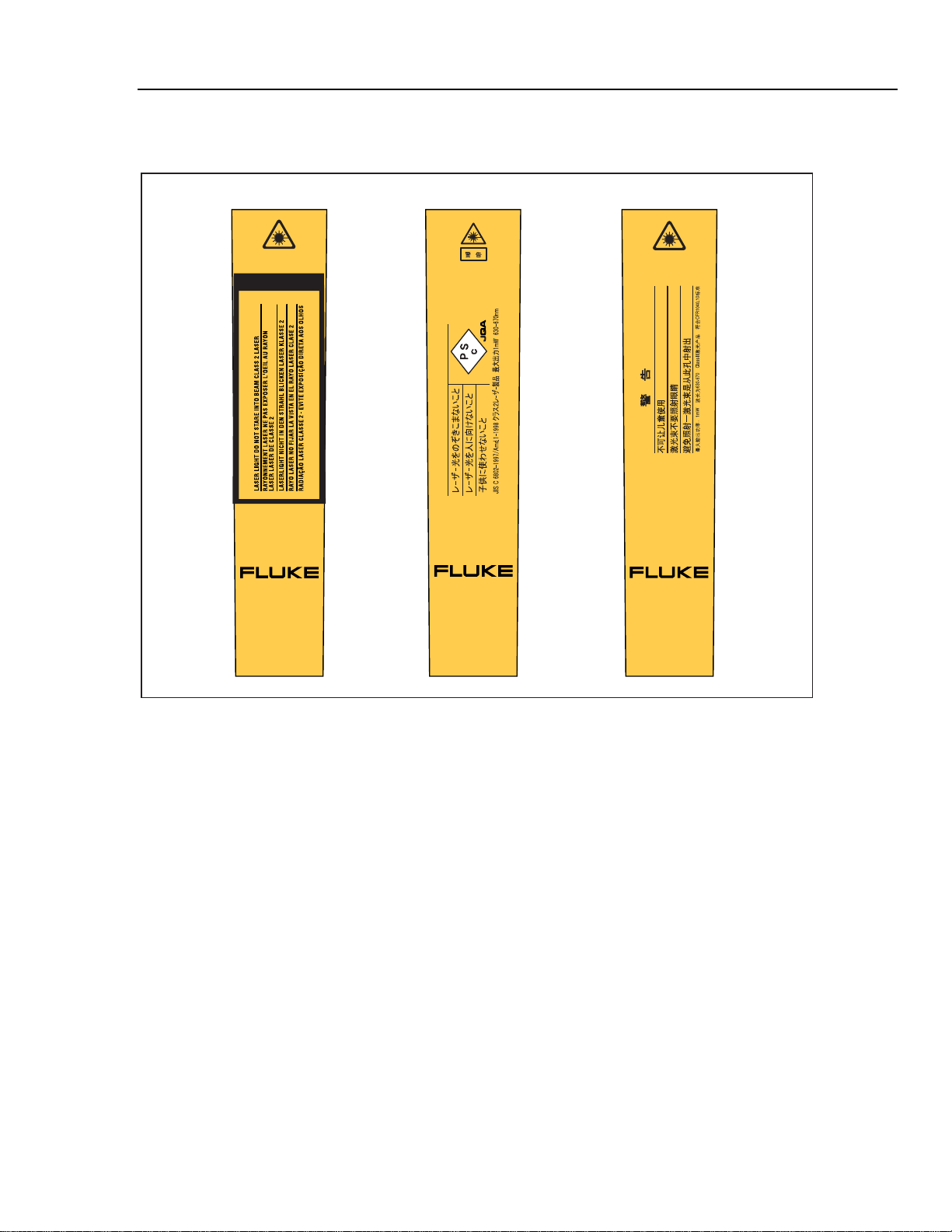
Laser Warning Labels 1
Laser Warning Labels
Euro/US Japanese Chinese
<
1mW/630-670nm
EN 60825/01
CAUTION
CAUTION
CAUTION
Ti20
THERMAL IMAGER
Ti20
THERMAL IMAGER
Figure 1-1. Laser Warning Labels
Ti20
THERMAL IMAGER
dag133f.eps
1-3
Ti20
Users Manual
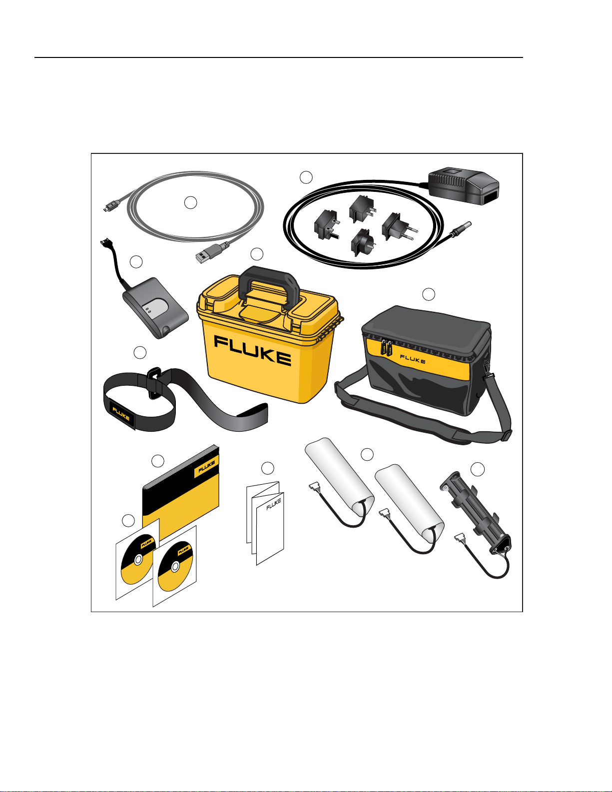
Unpacking the Imager
Begin by opening the shipping box. Be sure to save the box and shipping materials in
case you need to ship the Imager. Inside the shipping box, you will find a hard carrying
case containing the standard accessories shown in Figure 1-2 and described in Table 1-2.
2
1
3
6
10
9
4
5
7
11
8
1-4
Figure 1-2. Standard Accessories
dag134f.eps

Getting Started
Table 1-2. Standard Accessories
A PN 1671807 USB Cable B PN 2444076 International AC Adapter
Unpacking the Imager 1
PN 2507729 External Charger for
C
Rechargeable Battery Pack
D PN 2518704 Hard Case
E PN 2455818 Soft Case with Shoulder Strap F PN 2443380 Wrist Strap
G PN 2446641 Rechargeable Battery Pack (2) H PN 2455807 AA Battery Tray
PN 2492146 CD-ROM with InsideIR
software and Users Manual and
I
PN 2492154 Ti20 Training Material
J PN 2492168 Getting Started Guide
K PN 2492228 Quick Reference Guide
1-5

Ti20
Users Manual
Features and Controls
Imager features and controls are shown in Figure 1-3 and described in Table 1-3.
1
Ti20
THERMAL IMAGER
2
3
CAUTION
AVOID EXPOSU
RE
LASER RADIATION
IS EMITTED
FR
OM
THIS APER
TUR
E
DO NO
T ST
ARE
INTO BEAM
OUTPUT <
1mW
WAVELENGTH:
630 - 670
nm
CLASS II
LASER
PRODUCT
COMPLIES
WITH
CFR 1040.
10
Ti20
T
HE
RM
A
L I
MAGE
R
7
5
6
8
9
ER
Ti20
AG
MAL IM
ER
H
T
10
4
11
1-6
dag01f.eps
Figure 1-3. Ti20 Thermal Imager Features and Controls

Getting Started
Table 1-3. Features and Controls
Number Description
A Focus control
B Optical channel
C Laser aperture
D Wrist strap and attachment clip
E Trigger. The trigger is used to freeze a thermal image. Press the trigger one time to freeze
the image for evaluation. You can save the image or press and release the trigger again to
delete the image.
F USB port
G AC adapter terminal
H Display
I The three soft keys (F, G, and H) are used to navigate the menu structure of the
Imager, access all functions, and select values for the various adjustable parameters. The
Operating the Controls 1
G soft key is also used to turn the Imager On and Off. Press and hold G for two
seconds to turn off the Imager.
J Battery compartment
K Threaded tripod mount
Operating the Controls
The following sections describe the purpose and function of the two Imager controls,
focus and trigger.
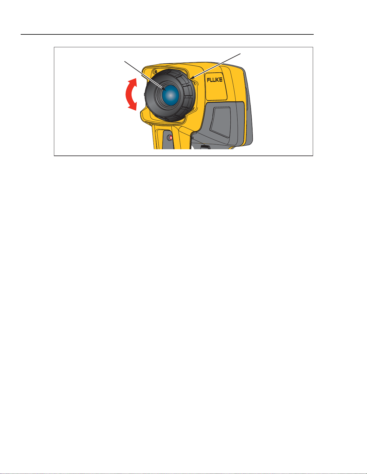
Focusing the Imager
Proper focus is critically important in radiometric imaging applications. The correct focus
ensures that the infrared energy is being properly directed onto the pixels of the detector.
Without the correct focus, the thermal image appears blurry and the radiometric data will
be inaccurate. Correct focus is necessary to accurately capture a thermal image.
Focus the Imager by turning the focus control in a clockwise or counterclockwise
direction (similar to the operation of a single lens reflex 35 mm photographic camera).
The Imager is designed to focus at a minimum distance of 61 cm (24 in) or less (rotated
fully clockwise as viewed from the rear of the instrument) and to a maximum of infinity
(rotated fully counterclockwise).
As you turn the focus control, you will see a changing, live, thermal image on the display.
When your target comes into focus, it will appear sharper. When the target moves out of
focus, it becomes blurry. One way to verify proper focus is to find what focus adjustment
produces the highest temperature indication on the display (keeping emissivity and
Reflected Temperature Compensation (RTC) values constant, preferably with emissivity
set at 1.0 and RTC disabled). See Figure 1-4 for an illustration of focusing the Imager.
1-7
Ti20
Users Manual
Optical Channel
Understanding the Trigger
The trigger is located in the standard trigger position for a pistol-grip device. The primary
function of the trigger is to freeze a thermal image for possible storage to memory by the
user. The trigger freezes an image in the following modes:
Ti20
THERMAL IMAGER
Figure 1-4. Focusing the Imager
Focus Ring
dag02f.eps
• In automatic temperature level and span adjustment mode
• In manual temperature level and span adjustment mode
• When scrolling through the menu levels (without entering a menu selection)
1-8
Getting Started
Using the AC Power Adapter 1
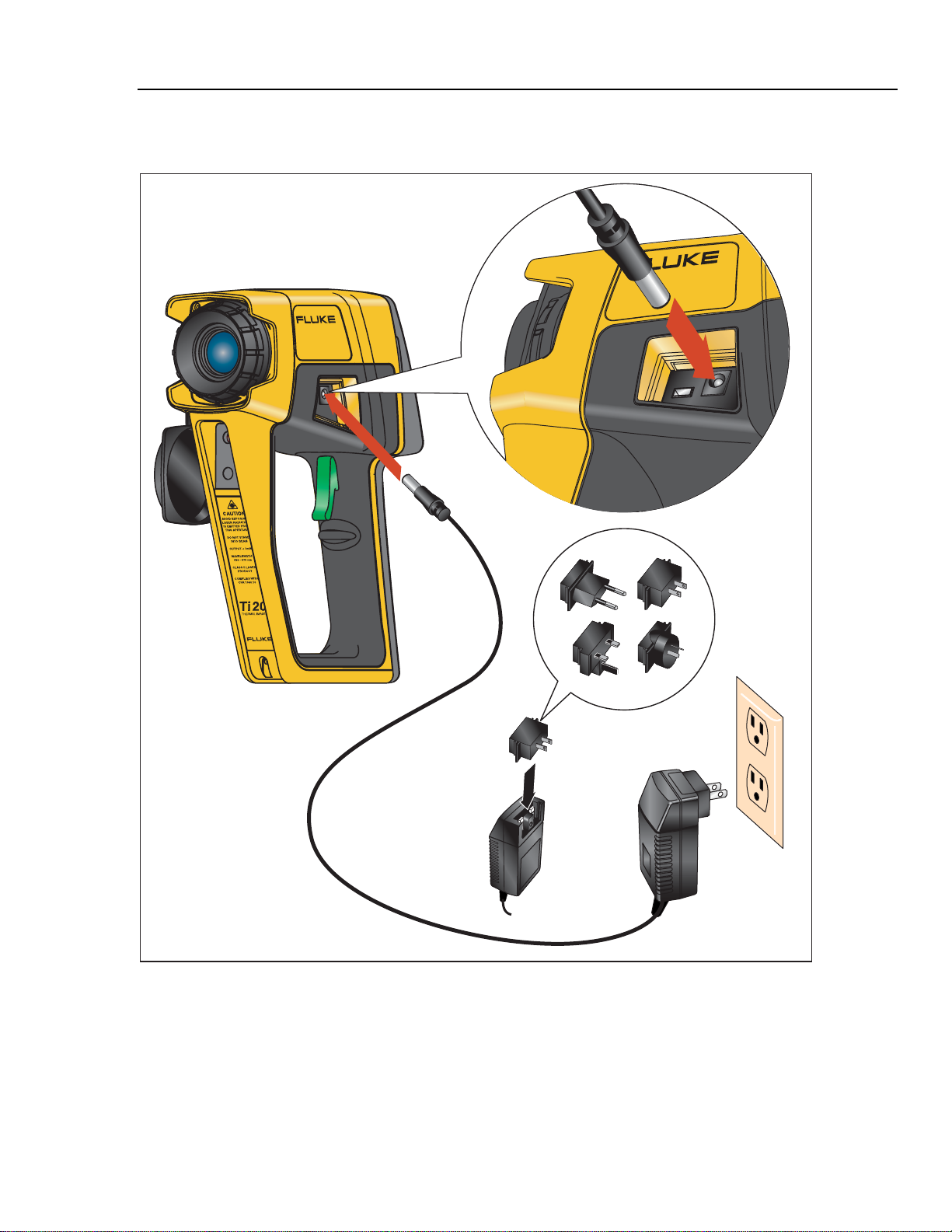
Using the AC Power Adapter
Ti20
THERMAL IMAGER
Ti20
R
E
G
L IMA
A
M
R
E
TH
dag007f.eps
Figure 1-5. Using the AC Power Adapter
1-9
Ti20
Users Manual
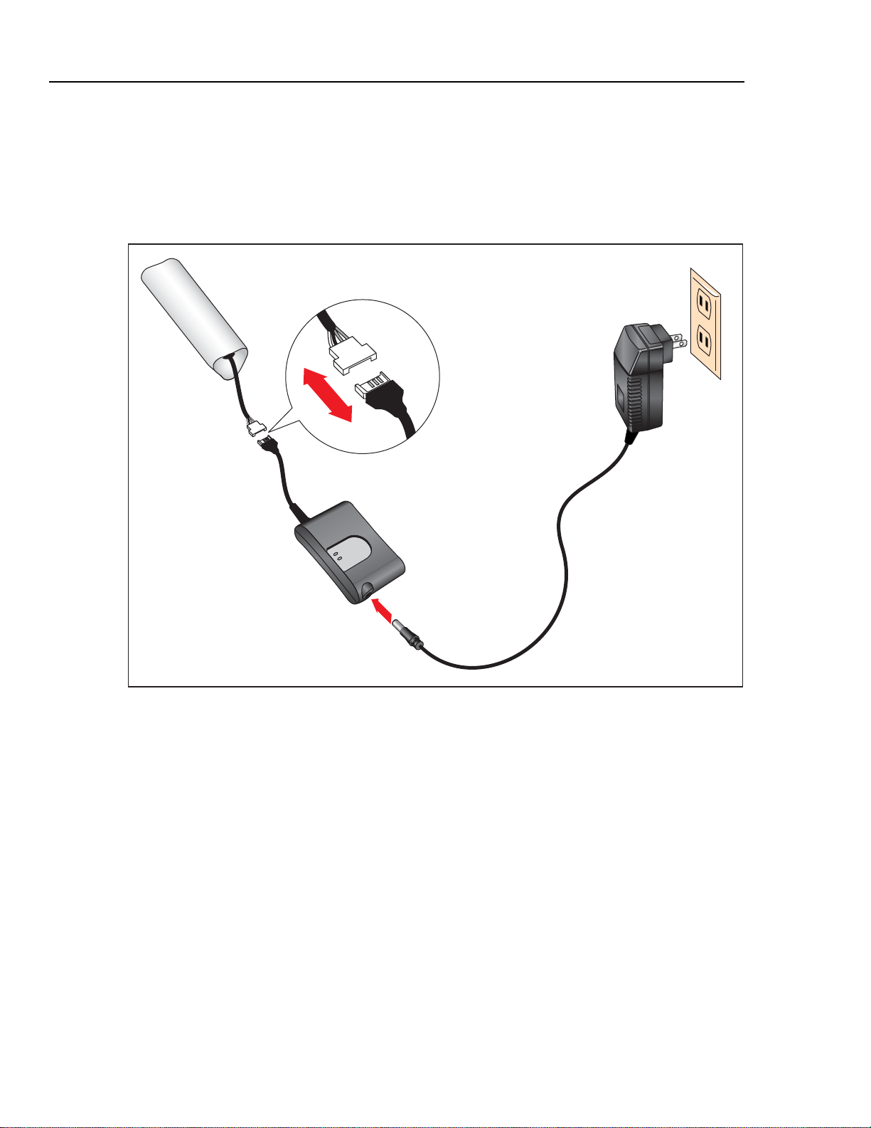
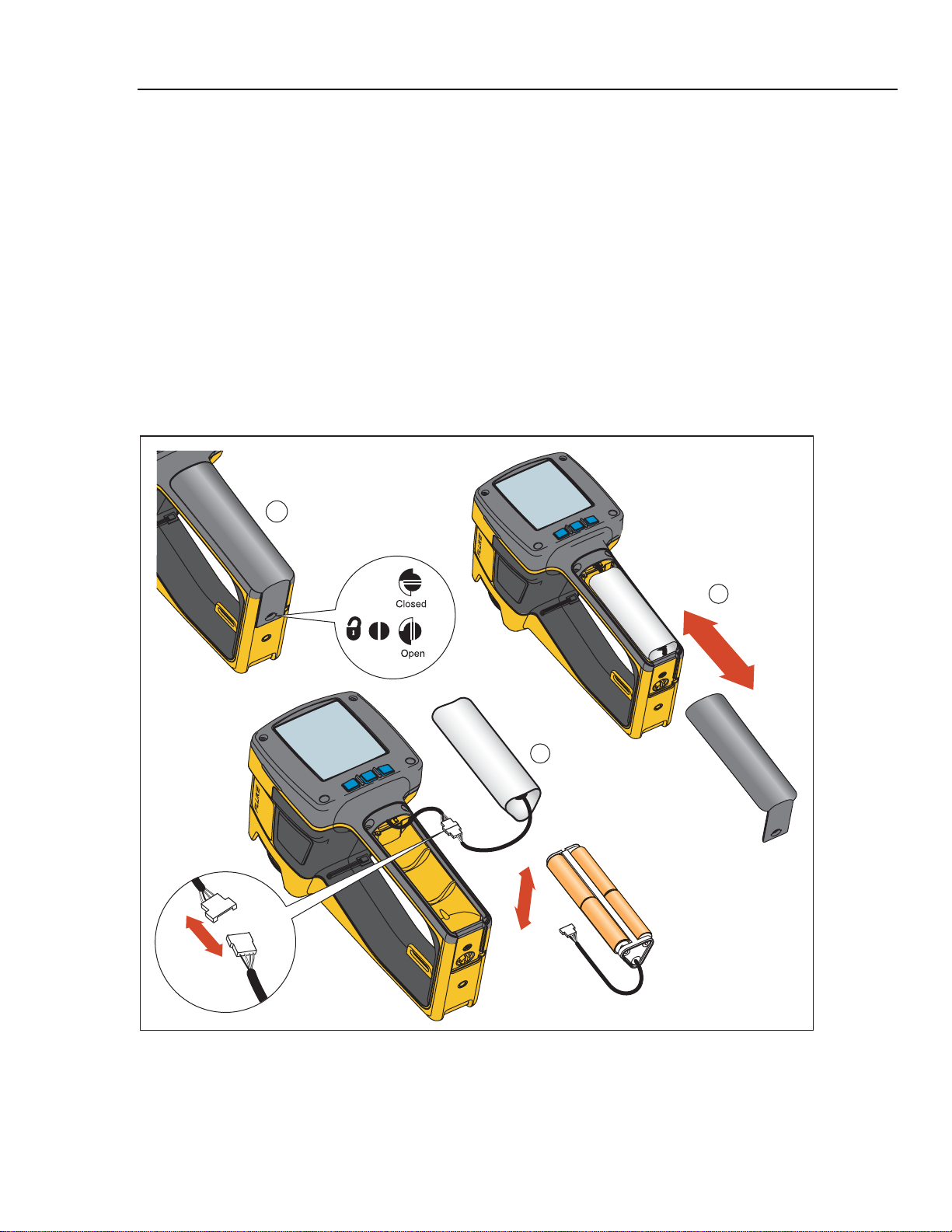
Charging and Replacing the Batteries
With the Ti20, you have the option of using six AA batteries or a rechargeable NiMH
pack. The use of both options is described in the following pages. Battery charger use is
shown is Figure 1-6 and battery placement in Figure 1-7 .
Using the Battery Charger
.
1-10
Figure 1-6. Using the Battery Charger
dag008f.eps
Getting Started
Charging and Replacing the Batteries 1
Installing or Replacing the Batteries
Replace the batteries with six AA batteries (NEDA 15A or IEC LR6). Install or Replace
the AA battery cartridge as described below and shown in Figure 1-7.
1. Unlock the battery compartment by using a standard screwdriver to turn the
battery door screw one-quarter turn counterclockwise.
2. Slide the battery compartment door off the grip.
3. Uncouple the battery connector and remove the rechargeable battery (or battery
pack).
4. Change the rechargeable battery (or battery pack with fresh batteries).
5. Replace and reconnect the rechargeable battery (or battery pack.
6. Replace the battery door. Secure the door by turning the screw one-quarter turn
clockwise.
Ti20
1
R
E
AG
IM
L
A
M
R
Ti20
E
TH
2
3
THERMAL IMA GER
OR
dag03f.eps
Figure 1-7. Replacing the Battery Pack
1-11
Ti20
L
Ti
20
L
Ti
20
Users Manual
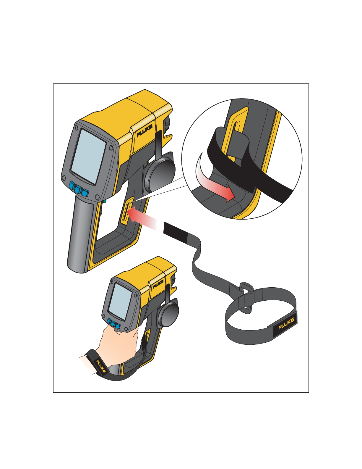
Attaching the Wrist Strap
A wrist strap is included with your Imager. You can attach the wrist strap by clipping the
strap to the attachment clip on the Imager housing.
IMAGER
20
AL
Ti
RM
HE
T
R
E
MAG
I
20
L
Ti
RMA
HE
T
1-12
Figure 1-8. Attaching the Wrist Strap
dag131f.eps
Getting Started
Inputs and Connections 1
Inputs and Connections
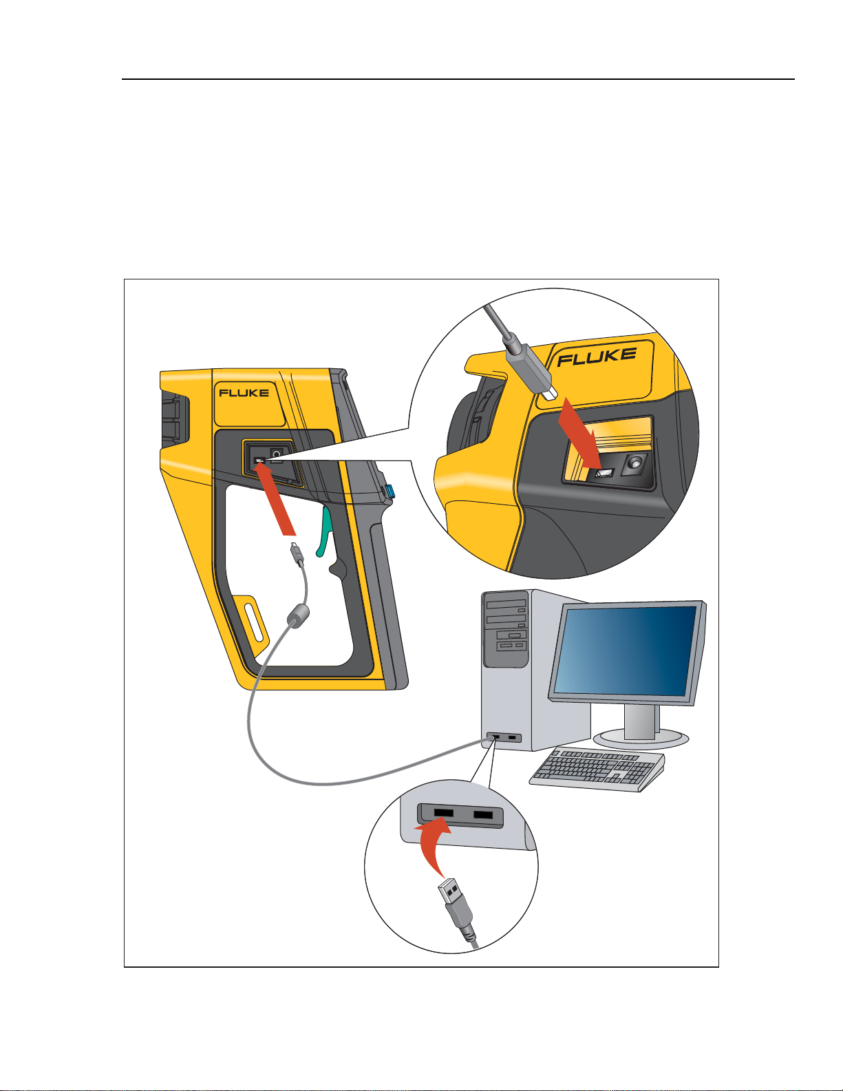
Connecting the USB Cable
The included USB cable can be used to either download or upload data from a PC to the
Imager. To connect the USB cable, insert the smaller USB connector into the Imager port
and the larger connector into the PC USB port as shown in Figure 1-9. Communications
begin automatically, and a USB symbol (I) appears in the header area of the Imager
display when communications are established.
Ti20
Ti20
THERMAL IMAGER
THERMAL IMAGER
Figure 1-9. Connecting Using the USB Cable
1-13
dag009f.eps
Loading...