


NetDAQ 2640A

®
2640A/2645A
NetDAQ
Networked Data Acquisition Unit
Users Manual
PN 942623
May 1994, Rev 2 11/96
© 1994, 1995, 1996 Fluke Corporation, All rights reserved. Printed in U.S.A.
All product names are trademarks of their respective companies.


LIMITED WARRANTY & LIMITATION OF LIABILITY
Each Fluke product is warranted to be free from defects in material and workmanship under
normal use and service. The warranty period is one year and begins on the date of
shipment. Parts, product repairs and services are warranted for 90 days. This warranty
extends only to the original buyer or end-user customer of a Fluke authorized reseller, and
does not apply to fuses, disposable batteries or to any product which, in Fluke’s opinion,
has been misused, altered, neglected or damaged by accident or abnormal conditions of
operation or handling. Fluke warrants that software will operate substantially in accordance
with its functional specifications for 90 days and that it has been properly recorded on non-
defective media. Fluke does not warrant that software will be error free or operate without
interruption.
Fluke authorized resellers shall extend this warranty on new and unused products to end-
user customers only but have no authority to extend a greater or different warranty on
behalf of Fluke. Warranty support is available if product is purchased through a Fluke
authorized sales outlet or Buyer has paid the applicable international price. Fluke reserves
the right to invoice Buyer for importation costs of repair/replacement parts when product
purchased in one country is submitted for repair in another country.
Fluke’s warranty obligation is limited, at Fluke’s option, to refund of the purchase price, free
of charge repair, or replacement of a defective product which is returned to a Fluke
authorized service center within the warranty period.
To obtain warranty service, contact your nearest Fluke authorized service center or send
the product, with a description of the difficulty, postage and insurance prepaid (FOB
Destination), to the nearest Fluke authorized service center. Fluke assumes no risk for
damage in transit. Following warranty repair, the product will be returned to Buyer,
transportation prepaid (FOB Destination). If Fluke determines that the failure was caused
by misuse, alteration, accident or abnormal condition of operation or handling, Fluke will
provide an estimate of repair costs and obtain authorization before commencing the work.
Following repair, the product will be returned to the Buyer transportation prepaid and the
Buyer will be billed for the repair and return transportation charges (FOB Shipping Point).
THIS WARRANTY IS BUYER’S SOLE AND EXCLUSIVE REMEDY AND IS IN LIEU OF
ALL OTHER WARRANTIES, EXPRESS OR IMPLIED, INCLUDING BUT NOT LIMITED TO
ANY IMPLIED WARRANTY OF MERCHANTABILITY OR FITNESS FOR A PARTICULAR
PURPOSE. FLUKE SHALL NOT BE LIABLE FOR ANY SPECIAL, INDIRECT,
INCIDENTAL OR CONSEQUENTIAL DAMAGES OR LOSSES, INCLUDING LOSS OF
DATA, WHETHER ARISING FROM BREACH OF WARRANTY OR BASED ON
CONTRACT, TORT, RELIANCE OR ANY OTHER THEORY.
Since some countries or states do not allow limitation of the term of an implied warranty, or
exclusion or limitation of incidental or consequential damages, the limitations and
exclusions of this warranty may not apply to every buyer. If any provision of this Warranty is
held invalid or unenforceable by a court of competent jurisdiction, such holding will not
affect the validity or enforceability of any other provision.
Fluke Corporation Fluke Europe B.V.
P.O. Box 9090 P.O. Box 1186
Everett WA 5602 B.D.
98206-9090 Eindhoven
The Netherlands
5/94

PCaution
This is an IEC safety Class 1 product. Before usi ng, the
ground wire in the line cord or rear panel binding post
must be connect to an earth ground for safety.
Interference Information
This equipment generates and uses radio frequency energy and if not installed and used in strict
accordance with the manufacturer’s instructions, may cause interference to radio and television
reception. It has been type tested and found to comply with the limits for a Class B computing device
in accordance with the specifications of Part 15 of FCC Rules, which are designed to provide
reasonable protection against such interference in a residential installation.
Operation is subject to the following two conditions:
• This device may not cause harmful interference.
• This device must accept any interference received, including interference that may cause
undesired operation.
There is no guarantee that interference will not occur in a particular installation. If this equipment
does cause interference to radio or television reception, which can be determined by turning the
equipment off and on, the user is encouraged to try to correct the interference by one of more of the
following measures:
• Reorient the receiving antenna
• Relocate the equipment with respect to the receiver
• Move the equipment away from the receiver
• Plug the equipment into a different outlet so that the computer and receiver are on different
branch circuits
If necessary, the user should consult the dealer or an experienced radio/television technician for
additional suggestions. The user may find the following booklet prepared by the Federal
Communications Commission helpful: How to Identify and Resolve Radio-TV Interference Problems.
This booklet is available from the U.S. Government Printing Office, Washington, D.C. 20402. Stock
No. 004-000-00345-4.
Declaration of the Manufacturer or Importer
We hereby certify that the Fluke Model 2640A/2645A Networked Data Acquisition Unit is in
compliance with BMPT Vfg 243/1991 and is RFI suppressed. The normal operation of some
equipment (e.g. signal generators) may be subject to specific restrictions. Please observe the
notices in the users manual. The marketing and sales of the equipment was reported to the Central
Office for Telecommunication Permits (BZT). The right to retest this equipment to verify compliance
with the regulation was given to the BZT.
Bescheinigung des Herstellers/Importeurs
Hiermit wird bescheinigt, daβ Fluke Models 2640A/2645A Networked Data Acquisition Unit in
Übereinstimung mit den Bestimmungen der BMPT-AmtsblVfg 243/1991 funk-entstört ist. Der
vorschriftsmäßige Betrieb mancher Geräte (z.B. Meßsender) kann allerdings gewissen
Einschränkungen unterliegen. Beachten Sie deshalb die Hinweise in der Bedienungsanleitung. Dem
Bundesamt für Zulassungen in der Telekcommunikation wurde das Inverkehrbringen dieses Gerätes
angezeigt und die Berechtigung zur Überprüfung der Seire auf Einhaltung der Bestimmungen
eingeräumt.
Fluke Corporation
SAFETY TERMS IN THIS MANUAL
This instrument has been designed and tested in accordance with IEC publicat ion
1010-1,
Safety Requirements for Electr ical M easur ing, Control and Laboratory
Equipment
. This Users Manual contains information, war nings and caut ions. Use
of this equipment in a manner not specified herein m ay impair the protection
provided by the equipment.
This instrument is designed for IEC 1010-1 Inst allation Category II use.
WARNING statements ident ify conditions or practices that could result in personal
injury or loss of life.
CAUTION statements identify condit ions or pr actices that could result in damage
to equipment.
SYMBOLS MARKED ON EQUIPMENT:
WARNING Risk of electric shock.
Ground (earth) terminal.
Protective ground (earth) ter m inal. M ust be connected to safety earth
ground when the power cord is used.
Attention. Refer to the m anual ( see the Index for references). This
symbol indicates that information about usage of a feature is contained
in the manual. This symbol appears on the Universal Input M odule and
in the following three places on the instrument rear panel:
1. Ground Binding Post (to the left of t he line power connector).
2. Ground Binding Post (to the left of t he 10Base2 connect or).
3. ALARM/TRIGGER I/O and DIGITAL I/O connectors.
AC POWER SOURCE
The instrument is intended to operate from an ac power source that will not apply
more than 264V ac rms between the supply conductors or bet ween either supply
conductor and ground. A protective ground connection by way of the grounding
conductor in the power cord is required for saf e oper ation.

DC POWER SOURCE
The instrument may also be operated from a 9V to 16V dc power source when
either the rear panel ground binding post or the power cor d grounding conductor
is connected properly.
USE THE PROPER FUSE
To avoid fire hazard, for fuse replacement use only a 1/ 4 am pere, 250V non-time
delay line fuse.
GROUNDING THE INSTRUMENT
The instrument utilizes controlled overvoltage techniques that require the
instrument to be grounded whenever normal m ode or com mon mode ac voltages
or transient voltages may occur. The enclosure m ust be grounded through the
grounding conductor of the power cord, or if operated on battery with the power
cord unplugged, through the rear panel ground binding post.
USE THE PROPER POWER CORD
Use only the power cord and connector appropriate for the voltage and plug
configuration in your country.
Use only a power cord that is in good condition.
Refer power cord and connector changes to qualified service personnel.
WARNING!
DO NOT OPERATE IN EXPLOSIVE ATM O SPHERES
To avoid personal injury or death, do not remove the instrument cover without first
removing the power source connected to the rear panel. Do not operate the
instrument without the cover proper ly installed. Normal calibration is accomplished
with the cover closed. There is no need for the operator to remove the cover
except to replace the fuse. Access procedures and the warnings for such
procedures are contained both in this manual and in the Service Manual. Service
procedures are for qualified service personnel only.
DO NOT ATTEMPT TO OPERATE IF PROTECTION MAY BE IMPAIRED
If the instrument appears damaged or operates abnormally, protection may be
impaired. Do not attempt to operate the instrument under these condit ions. Refer
all question of proper instrument operat ion t o qualified service personnel.

i
Table of Contents
Chapter Title Page
1 Overview........................................................................................... 1-1
1-1. Introduction.......................................................................................... 1-3
1-2. Instrument Features and Capabilities................................................... 1-4
1-3. Analog Channels.............................................................................. 1-7
1-4 Computed Channels......................................................................... 1-7
1-5. Channel Numbering......................................................................... 1-7
1-6. Mx+B Scaling.................................................................................. 1-7
1-7. Alarms.............................................................................................. 1-8
1-8. Channel Monitoring......................................................................... 1-8
1-9. Digital I/O........................................................................................ 1-8
1-10. Totalizer........................................................................................... 1-8
1-11. Trigger Input .................................................................................... 1-9
1-12. Trigger Output.................................................................................. 1-9
1-13. Master Alarm ................................................................................... 1-10
1-14. Interval Trigger................................................................................ 1-10
1-15. External Trigger............................................................................... 1-10
1-16. Alarm Trigger................................................................................... 1-10
1-17. NetDAQ Logger Features and Capabilities.......................................... 1-11
1-18. Operating a NetDAQ Data Acquisition System................................... 1-11
1-19. Isolated Networks............................................................................. 1-12
1-20. General Networks............................................................................. 1-12
1-21. Ethernet Port Selection .................................................................... 1-12
1-22. Asynchronous Instrument Operations.............................................. 1-12
1-23. Group Instrument Operations........................................................... 1-12
1-24. Scanning and Logging...................................................................... 1-13
1-25. RS-232 Interface .............................................................................. 1-13
1-26. Host Computer Requirements .............................................................. 1-14
1-27. Options and Accessories ...................................................................... 1-14
1-28. Instrument Connector Set................................................................. 1-15
1-29. Host Computer Ethernet Adapters................................................... 1-15

2640A/2645A NetDAQ
Users Manual
ii
2 Preparing for Operation .................................................................. 2-1
2-1. Introduction.......................................................................................... 2-3
2-2. Instrument Preparation......................................................................... 2-3
2-3. Unpacking and Inspecting the Instrument....................................... 2-5
2-4. Positioning and Rack Mounting...................................................... 2-5
2-5. Connecting to a Power Source and Grounding ............................... 2-5
2-6. AC Power.................................................................................... 2-6
2-7. DC Power.................................................................................... 2-7
2-8. Grounding and Common Mode Voltage..................................... 2-7
2-9. Universal Input Module Connections.............................................. 2-7
2-10. Shielded Wiring........................................................................... 2-11
2-11. Crosstalk Considerations............................................................. 2-11
2-12. Digital I/O Connections................................................................... 2-11
2-13. Digital I/O.................................................................................... 2-12
2-14. Totalizer ...................................................................................... 2-12
2-15. Alarm/Trigger I/O Connections....................................................... 2-12
2-16. Trigger Input................................................................................ 2-13
2-17. Trigger Output............................................................................. 2-14
2-18. Master Alarm............................................................................... 2-14
2-19. External Trigger Wiring for a Group Instrument ............................ 2-15
2-20. Controls and Indicators.................................................................... 2-15
2-21. Front Panel Controls ................................................................... 2-17
2-22. Front Panel Indicators................................................................. 2-18
2-23. Rear Panel Controls..................................................................... 2-20
2-24. Rear Panel Indicators .................................................................. 2-20
2-25. Front Panel Operating Procedures................................................... 2-21
2-26. Power-On Options....................................................................... 2-21
2-27. Displaying a Monitor Channel.................................................... 2-22
2-28. Displaying the Digital I/O Status................................................ 2-24
2-29. Displaying the Totalizer Status................................................... 2-26
2-30. Reviewing and Setting the Base Channel Number ..................... 2-27
2-31. Reviewing and Setting the Line Frequency................................ 2-29
2-32. Reviewing and Setting the Network Type .................................. 2-31
2-33. Reviewing and Setting the General Network Socket Port .......... 2-36
2-34. Reviewing and Setting the General Network IP Address........... 2-37
2-35. Reviewing and Setting the Subnet Mask and Default Gateway.. 2-38
2-36. Viewing the Instrument Ethernet Address.................................. 2-41
2-37. Host Computer and Network Preparation............................................ 2-43
2-38. Installing Host Computer Ethernet Adapter.................................... 2-43
2-39. Instrument and Host Computer Interconnection.............................. 2-45
2-40. Host Computer/Instrument Direct Connection........................... 2-45
2-41. Interconnection Using 10Base2 (Coaxial) Wiring...................... 2-48
2-42. Interconnection Using 10BaseT (Twisted-Pair) Ethernet Wiring 2-48
2-43. Installing Host Computer Networking Software............................. 2-50

Contents
(continued)
iii
2-44. Setting Host Computer Networking Parameters.............................. 2-51
2-45. Installing NetDAQ Logger............................................................... 2-52
2-46. Installing NetDAQ Logger with Trumpet.................................... 2-53
2-47. Changing from an Isolated Network to a General Network........ 2-54
2-48. Installing Trend Link for Fluke (Optional)...................................... 2-55
2-49. Testing and Troubleshooting................................................................ 2-55
2-50. Testing the Installation..................................................................... 2-55
2-51. Troubleshooting Network Problems................................................ 2-58
3 Configuring NetDAQ Logger for Windows..................................... 3-1
3-1. Introduction.......................................................................................... 3-3
3-2. Starting NetDAQ Logger................................................................. 3-3
3-3. The Main Window........................................................................... 3-3
3-4. Accessing NetDAQ Logger Commands.......................................... 3-3
3-5. Configuring Network Communications ............................................... 3-4
3-6. The Communications Configuration Dialog Box............................ 3-5
3-7. Adding an Instrument to the Network.............................................. 3-5
3-8. Deleting an Instrument from the Network....................................... 3-7
3-9. Verifying Network Communications............................................... 3-7
3-10. Configuring the Current Setup............................................................. 3-8
3-11. Creating an Instrument Icon............................................................. 3-8
3-12. Deleting an Instrument Icon............................................................. 3-9
3-13. Designating Instruments as Group or Asynchronous....................... 3-9
3-14. Setup Files............................................................................................ 3-11
3-15. Saving the Current Setup in a File................................................... 3-11
3-16. Opening a Setup File........................................................................ 3-12
3-17. Starting NetDAQ Logger with a Setup File..................................... 3-13
3-18. Starting Logging Automatically....................................................... 3-14
3-19. NetDAQ Logger Command Line..................................................... 3-14
3-20. Configuring an Instrument.................................................................... 3-15
3-21. Dimmed Configuration Commands ................................................. 3-15
3-22. The Instrument Configuration Dialog Box...................................... 3-15
3-23. Configuring Channels........................................................................... 3-18
3-24. The Channels Configuration Dialog Box......................................... 3-18
3-25. Configuring Analog Channel Functions.......................................... 3-19
3-26. Configuring Computed Channel Functions ..................................... 3-20
3-27. Defining a Computed Channel Equation..................................... 3-20
3-28. Equation Syntax........................................................................... 3-21
3-29. Configuring Mx+B Scaling.............................................................. 3-22
3-30. Configuring Alarms ......................................................................... 3-23
3-31. Assigning Channel Labels................................................................ 3-24
3-32. Configuring Mx+B Scaling From a File .............................................. 3-24
3-33. Entering an Instrument’s Description................................................... 3-25
3-34. Copying a Channels Configuration...................................................... 3-26

2640A/2645A NetDAQ
Users Manual
iv
3-35. Default Configuration Settings............................................................ 3-27
3-36. Using Configuration Lockout.............................................................. 3-28
3-37. Saving an Instrument’s Configuration as a Text File.......................... 3-28
3-38. Configuring the netdaq.ini File............................................................ 3-29
4 Operating NetDAQ Logger for Windows........................................ 4-1
4-1. Introduction.......................................................................................... 4-3
4-2. Starting and Stopping Logging............................................................ 4-3
4-3. Starting or Stopping all Instruments at Once................................... 4-4
4-4. Starting or Stopping a Group Instrument......................................... 4-4
4-5. Clearing an Instrument’s Totalizer Value....................................... 4-5
4-6. Simulated Logging........................................................................... 4-5
4-7. Selecting an Instrument’s Scanning Duration ................................. 4-5
4-8. Real-Time Displays.............................................................................. 4-6
4-9. The Logging Status Window........................................................... 4-7
4-10. The Readings Table Window.......................................................... 4-8
4-11. The Spy Window............................................................................. 4-9
4-12. Quick Plot........................................................................................ 4-11
4-13. Dynamic Data Exchange (DDE) Operations................................... 4-12
4-14. Data Files ............................................................................................. 4-13
4-15. Configuring a Data File4-15............................................................ 4-14
4-16. Converting Data Files...................................................................... 4-18
4-17. Viewing and Printing a Data File.................................................... 4-18
4-18. Optimizing Performance...................................................................... 4-20
4-19. Optimizing Performance for Speed................................................. 4-20
4-20. Increasing Scanning Rate............................................................ 4-20
4-21. Increasing Data Transmission and Storage Rate......................... 4-20
4-22. Increasing Network Speed........................................................... 4-21
4-23. Optimizing Performance for Precision............................................ 4-21
4-24. Using Online Help ............................................................................... 4-21
5 Using Trend Link for Fluke.............................................................. 5-1
5-1. Introduction.......................................................................................... 5-3
5-2. Displaying a Trend Link Chart During Logging............................. 5-3
5-3. Playing Back a Trend Link File in Trend Link ............................... 5-4
5-4. Playing Back a Fast Binary File in Trend Link............................... 5-5
5-5. Playing Back an ASCII (CSV) File in Trend Link.......................... 5-6
5-6. Importing Trend Link Data Files..................................................... 5-6
5-7. Create a New Trend Link Data Set Directory............................. 5-6
5-8. Add the New Folder to the Trend Link infolink.ini File ... 5-6
5-9. Import the NetDAQ ASCII (CSV) File into Trend Link ............ 5-7
5-10. Display the Trend Link Chart for the Imported File................... 5-7
5-11. Title the Trend Link Chart .......................................................... 5-8
5-12. Save the Trend Link Chart.......................................................... 5-9

Contents
(continued)
v
5-13. Exporting Trend Link Data Files..................................................... 5-9
5-14. Deleting Old Trend Link Files......................................................... 5-11
5-15. Getting the Right Look for Your Trend Link Chart............................. 5-12
5-16. Using the Trend Link Control Bar................................................... 5-12
5-17. Using the Trend Link Menus........................................................... 5-15
5-18. Adjusting the Curve Time Scale (X-axis) ................................... 5-15
5-19. Adjusting the Curve Amplitude Scale (Y-axis)........................... 5-16
5-20. Configuring the Curve Status Display......................................... 5-17
5-21. Curve Preferences........................................................................ 5-18
5-22. Background Preferences.............................................................. 5-21
5-23. Real Time Frequency Update...................................................... 5-23
5-24. Adding or Changing the Chart Title............................................ 5-23
5-25. Using the Note System ................................................................ 5-24
5-26. Printing a Chart............................................................................ 5-24
6 Maintenance ..................................................................................... 6-1
6-1. Introduction.......................................................................................... 6-3
6-2. Self-Test Diagnostics and Error Codes................................................ 6-3
6-3. Cleaning................................................................................................ 6-4
6-4. Fuse Replacement................................................................................. 6-4
6-5. Performance Test.................................................................................. 6-6
6-6. Configuring the Performance Test Setup......................................... 6-6
6-7. Initializing the Performance Test Setup........................................... 6-9
6-8. Accuracy Performance Tests ........................................................... 6-11
6-9. Volts DC Accuracy Test (2640A) ............................................... 6-11
6-10. Volts DC Accuracy Test (2645A) ............................................... 6-12
6-11. Volts AC Accuracy Test.............................................................. 6-13
6-12. Frequency Accuracy Test............................................................ 6-14
6-13. Analog Channel Integrity Test..................................................... 6-15
6-14. Computed Channel Integrity Test................................................ 6-15
6-15. Thermocouple Temperature Accuracy Test................................ 6-16
6-16. Open Thermocouple Response Test............................................ 6-16
6-17. 2-Wire Resistance Accuracy Test (2640A)................................. 6-17
6-18. 2-Wire Resistance Accuracy Test (2645A)................................. 6-18
6-19. 4-Wire Resistance Accuracy Test (2640A)................................. 6-20
6-20. 4-Wire Resistance Accuracy Test (2645A)................................. 6-23
6-21. RTD Temperature Accuracy Test (Resistance) (2640A)............ 6-24
6-22. RTD Temperature Accuracy Test (Resistance) (2645A)............ 6-25
6-23. RTD Temperature Accuracy Test (DIN/IEC 751 RTD) ............. 6-25
6-24. Digital Input/Output Tests ............................................................... 6-26
6-25. Digital I/O Output Test................................................................ 6-26
6-26. Digital Input Test......................................................................... 6-27
6-27. Totalizer Tests.................................................................................. 6-28
6-28. Totalizer Count Test.................................................................... 6-28

2640A/2645A NetDAQ
Users Manual
vi
6-29. Totalizer Sensitivity Test............................................................ 6-28
6-30. Master Alarm Output Test............................................................... 6-29
6-31. Trigger Input Test............................................................................ 6-30
6-32. Trigger Output Test......................................................................... 6-30
6-33. Calibration............................................................................................ 6-31
6-34. Adding Calibration to the Utilities Menu........................................ 6-32
6-35. Instrument Calibration Dialog Box................................................. 6-33
6-36. Calibration Steps Dialog Box.......................................................... 6-33
6-37. Variations in the Display ..................................................................... 6-34
6-38. Service.................................................................................................. 6-34
6-39. Replacement Parts................................................................................ 6-36
Appendices
A Specifications........................................................................................... A-1
B Noise, Shielding, and Crosstalk Considerations ...................................... B-1
C True-RMS Measurements........................................................................ C-1
D RTD Linearization.................................................................................... D-1
E Computed Channel Equations.................................................................. E-1
F Data File Format....................................................................................... F-1
G Dynamic Data Exchange (DDE).............................................................. G-1
H Ethernet Cabling....................................................................................... H-1
I Network Considerations........................................................................... I-1
J Error Messages & Exception Conditions................................................. J-1
K Fluke Service Centers............................................................................... K-1
Index

vii
List of Tables
Table Title Page
1-1. Models, Options and Accessories................................................................... 1-14
2-1. Front Panel Key Descriptions ......................................................................... 2-17
2-2. Annunciator Display Descriptions.................................................................. 2-18
2-3. Instrument Default Parameters........................................................................ 2-21
2-4. Network Error Messages................................................................................. 2-58
2-5. Ethernet Indicators .......................................................................................... 2-60
2-6. Troubleshooting .............................................................................................. 2-61
3-1. NetDAQ Logger Default Instrument Configuration ....................................... 3-27
6-1. Self-Test Error Codes...................................................................................... 6-3
6-2. Recommended Test Equipment....................................................................... 6-7
6-3. Replacement Parts........................................................................................... 6-36
A-1. 2640A/2645A General Specifications............................................................. A-2
A-2. 2640A/2645A Environmental Specifications.................................................. A-4
A-3. 2640A/2645A DIGITAL I/O Specification..................................................... A-4
A-4. 2640A/2645A Trigger In (TI) Specification................................................... A-5
A-5. 2640A/2645A Trigger Out (TO) Specification............................................... A-6
A-6. 2640A/2645A Master Alarm (MA) Specification .......................................... A-6
A-7. 2640A/2645A Totalizer Specification ............................................................ A-7
A-8. 2640A/2645A Real-Time Clock and Calendar ............................................... A-7
A-9. 2640A DC Voltage Measurement General Specifications.............................. A-8
A-10. 2640A DC Voltage Range and Resolution Specifications.............................. A-8
A-11. 2640A DC Voltage Accuracy Specifications.................................................. A-9
A-12. 2640A AC Voltage General Specifications .................................................... A-9
A-13. 2640A AC Voltage Range and Resolution Specifications.............................. A-10
A-14. 2640A AC Voltage Accuracy Specifications.................................................. A-11
A-15. 2640A 4-Wire Resistance Temperature Coefficient....................................... A-12
A-16. 2640A 4-Wire Resistance Range and Resolution Specifications ................... A-12
A-17. 2640A 4-Wire Resistance Accuracy Specifications........................................ A-12
A-18. 2640A 4-Wire RTD Temperature Coefficient ................................................ A-13
A-19. 2640A 4-Wire RTD Specifications................................................................. A-13
A-20. 2640A Thermocouple General Specifications................................................ A-14

2640A/2645A NetDAQ
Users Manual
viii
A-21. 2640A Thermocouple Specifications ............................................................. A-15
A-22. 2640A Frequency Accuracy Specifications.................................................... A-16
A-23. 2640A Frequency Sensitivity Specifications.................................................. A-16
A-24. 2645A DC Voltage Measurement General Specifications............................. A-17
A-25. 2645A DC Voltage Resolution and Repeatability Specifications.................. A-18
A-26. 2645A DC Voltage Accuracy Specifications ................................................. A-18
A-27. 2645A AC Voltage General Specifications.................................................... A-19
A-28. 2645A AC Voltage Range and Resolution Specifications ............................. A-20
A-29. 2645A AC Voltage Accuracy Specifications ................................................. A-20
A-30. 2645A 4-Wire Resistance Temperature Coefficient....................................... A-21
A-31. 2645A 4-Wire Resistance Range and Resolution Specifications................... A-21
A-32. 2645A 4-Wire Resistance Accuracy Specifications....................................... A-21
A-33. 2645A 4-Wire RTD Temperature Coefficient................................................ A-22
A-34. 2645A 4-Wire RTD Specifications................................................................. A-22
A-35. 2645A Thermocouple General Specifications................................................ A-23
A-36. 2645A Thermocouple Specifications ............................................................. A-23
A-37. 2645A Frequency Accuracy Specifications.................................................... A-25
A-38. 2645A Frequency Sensitivity Specifications.................................................. A-25
B-1. 2645A Crosstalk Specifications...................................................................... B-3
B-2. 2640A Crosstalk Specifications...................................................................... B-4
I-1. Newt Quick Check.......................................................................................... I-29
I-2. Additions to Host Computer Files made by Newt Installation....................... I-30

ix
List of Figures
Figure Title Page
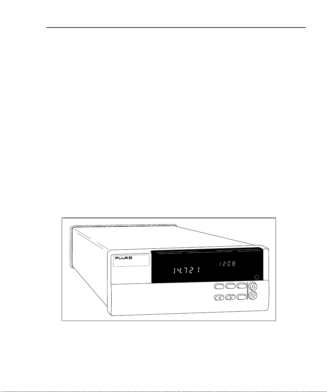
1-1. 2640A/2645A NetDAQ Networked Data Acquisition Units.......................... 1-3
1-2. 2640A/2645A Front Panel .............................................................................. 1-4
1-3. Typical Front Panel Display During Scanning and Monitoring ..................... 1-5
1-4. 2640A/2645A Rear Panel................................................................................ 1-6
2-1. Instrument Preparation.................................................................................... 2-4
2-2. Connecting the Instrument to a Power Source................................................ 2-6
2-3. Universal Input Module Connections ............................................................. 2-9
2-4. 2-Wire and 4-Wire Connections..................................................................... 2-10
2-5. DIGITAL I/O Connector................................................................................. 2-12
2-6. ALARM/TRIGGER I/O Connector................................................................ 2-14
2-7. External Trigger Wiring for a Group Instrument............................................ 2-16
2-8. Front Panel Controls........................................................................................ 2-17
2-9. Front Panel Indicators ..................................................................................... 2-18
2-10. Rear Panel Controls......................................................................................... 2-20
2-11. Rear Panel Indicators ...................................................................................... 2-20
2-12. Displaying a Monitor Channel ........................................................................ 2-22
2-13. Examples During Monitor............................................................................... 2-23
2-14. Displaying the Digital I/O Status .................................................................... 2-24
2-15. Examples for Digital I/O and Totalizer Status................................................ 2-25
2-16. Displaying the Totalizer Status ....................................................................... 2-26
2-17. Reviewing and Setting the Base Channel Number ......................................... 2-27
2-18. Examples for Reviewing and Setting the BCN............................................... 2-28
2-19. Reviewing and Setting the Line Frequency .................................................... 2-29
2-20. Examples for Reviewing and Setting the Line Frequency.............................. 2-30
2-21. Reviewing and Setting the Isolated Network Type to Isolated....................... 2-31
2-22. Examples for Reviewing and Setting the Network Type................................ 2-32
2-23. Reviewing and Setting the Network Type to General..................................... 2-33
2-24. Examples for Reviewing and Setting General Network Parameters............... 2-34
2-25. Reviewing and Setting the General Network Socket Port .............................. 2-36
2-26. Reviewing and Setting the General Network IP Address............................... 2-37
2-27. Reviewing and Setting the Subnet Mask and Default Gateway...................... 2-40

2640A/2645A NetDAQ
Users Manual
x
2-28. Viewing the Instrument Ethernet Address...................................................... 2-41
2-29. Examples for Viewing the Ethernet Address.................................................. 2-42
2-30. Preparing for Network Operation ................................................................... 2-44
2-31. Interconnection Using 10Base2 (Coaxial) Wiring.......................................... 2-46
2-32. Host Computer/Instrument Direct Connection............................................... 2-47
2-33. Interconnection Using 10BaseT (Twisted-Pair) Wiring................................. 2-49
3-1. NetDAQ Logger for Windows Main Window............................................... 3-4
3-2. Communications Configuration Dialog Box.................................................. 3-5
3-3. Instrument Configuration Dialog Box............................................................ 3-16
3-4. Channels Configuration Dialog Box............................................................... 3-18
3-5. Configuration Text File.................................................................................. 3-29
6-1. Replacing the Fuse.......................................................................................... 6-5
6-2. Performance Test Setup.................................................................................. 6-8
6-3. 2-Wire Connections to 5700A........................................................................ 6-8
6-4. 4-Wire Connections to the Universal Input Module (Resistor)...................... 6-20
6-5. 4-Wire Connections to the Universal Input Module (5700A)........................ 6-21
C-1. Comparison of Common Waveforms............................................................. C-3
D-1. 385 RTD ......................................................................................................... D-2
D-2. 375 RTD ......................................................................................................... D-3
D-3. 391 RTD ......................................................................................................... D-4
D-4. 392 RTD ......................................................................................................... D-6
H-1. 10BaseT Ethernet Cables................................................................................ H-2

1-1
Chapter 1
Overview
Contents Page
1-1. Introduction.......................................................................................... 1-3
1-2. Instrument Features and Capabilities................................................... 1-4
1-3. Analog Channels.............................................................................. 1-7
1-4. Computed Channels......................................................................... 1-7
1-5. Channel Numbering......................................................................... 1-7
1-6. Mx+B Scaling.................................................................................. 1-7
1-7. Alarms.............................................................................................. 1-8
1-8. Channel Monitoring......................................................................... 1-8
1-9. Digital I/O........................................................................................ 1-8
1-10. Totalizer........................................................................................... 1-8
1-11. Trigger Input.................................................................................... 1-9
1-12. Trigger Output.................................................................................. 1-9
1-13. Master Alarm................................................................................... 1-10
1-14. Interval Trigger................................................................................ 1-10
1-15. External Trigger............................................................................... 1-10
1-16. Alarm Trigger .................................................................................. 1-10
1-17. NetDAQ Logger Features and Capabilities.......................................... 1-11
1-18. Operating a NetDAQ Data Acquisition System................................... 1-11
1-19. Isolated Networks ............................................................................ 1-12
1-20. General Networks ............................................................................ 1-12
1-21. Ethernet Port Selection .................................................................... 1-12
1-22. Asynchronous Instrument Operations.............................................. 1-12
1-23. Group Instrument Operations........................................................... 1-12
1-24. Scanning and Logging...................................................................... 1-13
1-25. RS-232 Interface.............................................................................. 1-13
1-26. Host Computer Requirements.............................................................. 1-14
1-27. Options and Accessories ...................................................................... 1-14
1-28. Instrument Connector Set................................................................. 1-15
1-29. Host Computer Ethernet Adapters................................................... 1-15

2640A/2645A NetDAQ
Users Manual
1-2
Overview
Introduction
1
1-3
Introduction 1-1.
The 2640A and 2645A NetDAQ Networked Data Acquisition Units are
20-channel front ends that operate in conjunction with NetDAQ Logger for
Windows (hereafter known as NetDAQ Logger) to form a data acquisition
system.
The instruments measure dc volts, ac volts, Ohms, temperature, frequency, and dc
current. Temperature measurements use thermocouples or resistance-temperature
detectors (RTDs). To measure other parameters, use an appropriate transducer.
The instrument also includes ten computed channels for custom calculations
based on measured values.
The NetDAQ instruments scan the 20 analog channels in sequence and calculate
the values for the ten computed channels. Interval timers, alarm conditions, and/or
an external signal input can trigger scans. The NetDAQ Logger software
configures and controls up to 20 instruments via an Ethernet connection. The
software provides the means to view scan data and log it into files.
The 2640A and 2645A instruments (Figure 1-1) are identical in operation and
appearance, and vary only in emphasis. The 2640A emphasizes precision and
supports up to 100 measurements per second, with 5 ½ digits of resolution, .02%
accuracy, and 150-volt common mode voltage (300 volts on channels 1 and 11).
The 2645A emphasizes increased measurement speed supporting up to 1000
measurements per second, with 4 ½ digits of resolution, 0.04% accuracy, and 50-
volt common mode voltage. See Appendix A for instrument specifications.
NetDAQ
NETWORKED DATA ACQUISITION UNIT
COMM
DIO
MON
ENTER
CAL
ENABLE
REM SCAN
MON
V DC
CH
Figure 1-1. 2640A/2645A NetDAQ Networked Data Acquisition Units
2640A/2645A NetDAQ
Users Manual
1-4
Instrument Features and Capabilities 1-2.
The following describes the front and rear panels of the instrument and its
capabilities (Figures 1-2 to 1-4).
NetDAQ
NETWORKED DATA ACQUISITION UNIT
COMM
DIO MON
ENTER
CAL
ENABLE
REVIEW
LAST
MAX
MIN
REM
AUTO
SCAN
MON
SET
Mx+B
FUNC
ALARM
°C °F RO
mV AC DC
x1Mk
Hz
LIMIT
HI
LO
OFF
CAL
PRN
EXT
CH
TR
12
Ω
F
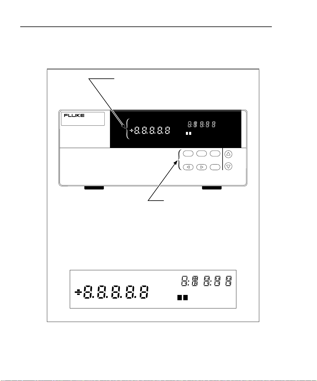
Primary, Secondary, and
Annunciator Displays.
Indicators and annunciators for
operating mode, configuration,
display, and data measurements.
Function Keys.
User keys for configuring
operating parameters such as
Base Channel Number, and front
panel displays such as channel
monitoring, digital I/O status, and
totalizer count.
REVIEW
LAST
MAX
MIN
REM
AUTO
SCAN
MON
SET
Mx+B
FUNC
ALARM
°C °F RO
mV AC DC
x1Mk
Hz
LIMIT
HI
LO
OFF
CAL
PRN
EXT
CH
TR
12
Ω
F
Display Detail
Figure 1-2. 2640A/2645A Front Panel
Overview
Instrument Features and Capabilities
1
1-5
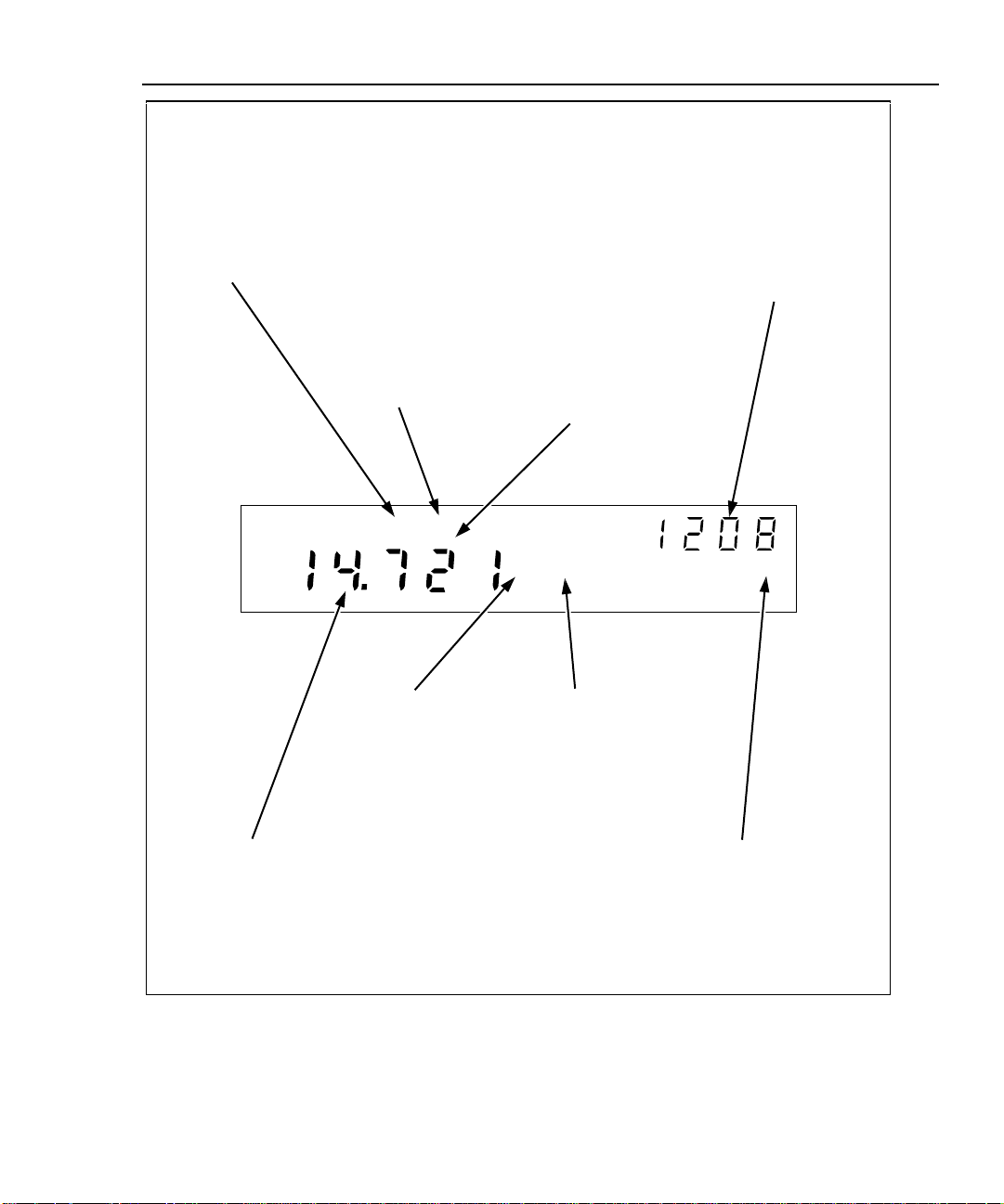
REM (Remote)
Annunciator.
Indicates the Host
Computer and the
Instrument are
communicating on the
network, i.e., the
instrument is being
operated remotely.
REM SCAN
MON
mV DC
CH
SCAN (Scanning)
Annunciator.
Indicates the
instrument is
scanning.
MON (Monitor)
Annunciator.
Indicates the
instrument is
monitoring a channel
(in this example,
analog channel 8).
You can monitor a
channel with or
without instrument
scanning.
1208 (Global Channel
Number).
Indicates the channel
being monitored is
1208. This number
consists of the
instrument Base
Channel Number (12)
and the selected
channel (08).
14.721 (Reading).
Indicates the reading
of the channel being
monitored has a value
of 14.721. This
display is limited to 4
1/2 digits of resolution.
m Annunciator.
Indicates the multiplier
for the reading is .001
(milli). The other
multipliers are k (kilo,
1000), and M (mega,
1,000,000).
V DC (Volts DC)
Annunciator.
Indicates that the
number shown in the
primary display
(14.721) is the
function volts dc.
CH (Channel)
Annunciator.
Indicates the number
shown in the
secondary display
(1208) is the Global
Channel Number.
Figure 1-3. Typical Front Panel Display During Scanning and Monitoring
2640A/2645A NetDAQ
Users Manual
1-6
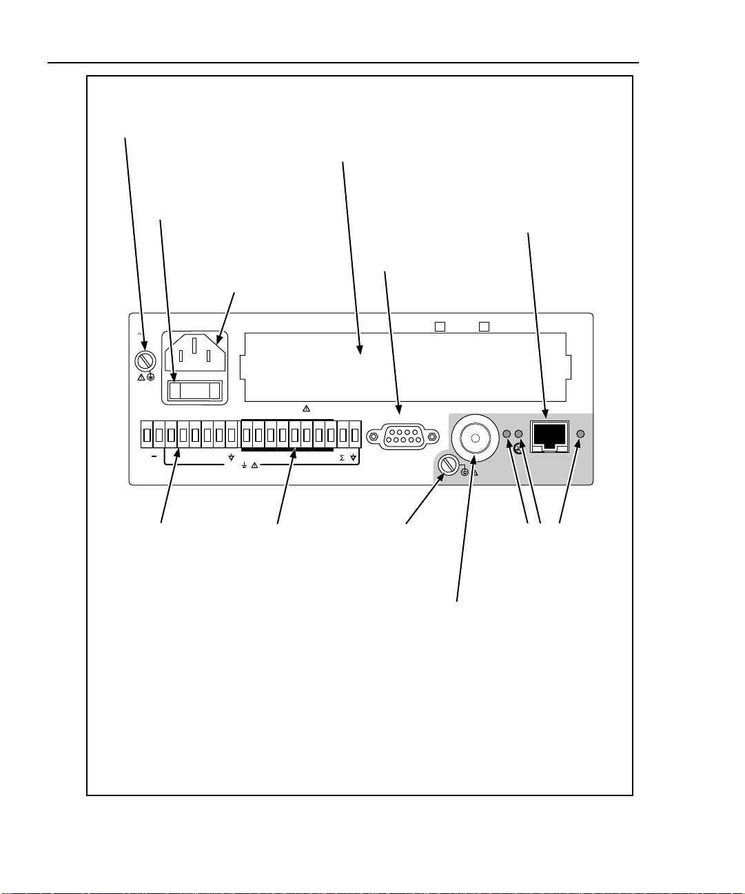
Serial Port.
ALARM/TRIGGER I/O
Connector.
MA (Master Alarm)
output is logic low when
any channel is in alarm;
TO (Trigger Output)
output is logic low for
nominal 125
µ
s at the
start of any scan; TI
(Trigger Input) input
logic low triggers
scanning; DC PWR (dc
volts input) input is 9 to
16V dc to power the
instrument.
DIGITAL I/O
Connector.
Alarm outputs (logic
low for a channel in
alarm) and general
purpose I/O (terminals
0 to 7); totalizer input,
and GND.
Universal Input Module.
Directly wires 20 analog inputs
(Channels 1 to 20) without need
for external signal conditioning.
Ground Terminal.
Connects mainframe to ground.
AC Power Connector.
Connects to any line
source of 107 to 264 volts
ac (50/60 Hz).
Power Switch.
Applies power to the
instrument (ac or dc
operation).
Ground Terminal.
Use for 50-ohm
termination ground
lug.
+
WARNING: TO AVOID ELECTRICAL SHOCK, DISCONNECT LINE CORD BEFORE REMOVING COVER
9-16V
DC PWR
DIGITAL I/O
MATO TI 0 1 2 3 4 5 6 7
+30V
ALARM/TRIGGER I/O
ETHERNET
NOT FOR CONNECTION TO
PUBLIC TELEPHONE SYSTEMS
MEETS VFG 243 / 1991
OVERVOLTAGE CATEGORY II PER IEC 1010-1
SERIAL PORT
MODEL: 2640A / 41A 2645A / 46A
ON/ OFF
XMT
RCV LK
107-264V
50/60 Hz
15VA
Ethernet 10BaseT
Connector.
A RJ-45 connector that
interfaces the instrument with
a 10BaseT Twisted-Pair
Ethernet network. The
instrument automatically
selects the active 10Base2 or
10BaseT connector.
Ethernet Indicators.
XMT (transmit) blinks
red for instrument
Ethernet transmissions;
RCV (receive) blinks
red for any Ethernet
activity on the network;
LK (link) lights amber
when the Ethernet
interface is active for
the Twisted-Pair
connection, and blinks
for a data collision for
the coaxial connection.
Ethernet 10Base2
Connector.
A BNC-type connector that
interfaces the instrument
with a 10Base2 coax
network. The instrument
automatically selects the
active 10Base2 or 10BaseT
connector.
Figure 1-4. 2640A/2645A Rear Panel

Overview
Instrument Features and Capabilities
1
1-7
Analog Channels 1-3.
The analog channel (1 to 20) measurement connections are made via the
Universal Input Module. External signal conditioning for the analog inputs is not
necessary. The host computer configures all analog channels using NetDAQ
Logger.
Computed Channels 1-4.
In addition to the 20 analog channels, the instrument provides an additional 10
computed channels (21 to 30) by processing analog channels and other computed
channels. The following methods are used:
• The average of a group of channels,
• The difference between any two channels,
• The difference between a channel and the average of a group of channels,
• A mathematical equation.
Channel Numbering 1-5.
Each instrument channel, measured or computed, is identified by Global Channel
Number (GCN). The first two digits of the GCN are the Base Channel Number
(01 to 99) that identifies the instrument. The last two digits are the channel
number. For example, GCN 2618 indicates instrument 26 and analog channel 18
(below). When the instrument is in the quiescent state, the channel number of the
GCN shows dashes, for example, 45-- for instrument 45.
Mx+B
ALARM
CH
SCAN
MON
Mx+B Scaling 1-6.
Mx+B scaling multiplies a measurement by a multiplier M and then offsets it by
an offset B. For example, Mx+B scaling of 100x+50 applied to a measured or
computed channel value of 1.15 results in a reading of 100(1.15)+50=165. A
common use of Mx+B scaling is to calibrate a sensor or transducer to provide for
display and recording in engineering units. The Mx+B annunciator lights when a
monitored channel has scaling applied.

2640A/2645A NetDAQ
Users Manual
1-8
Alarms 1-7.
Two alarms, Alarm 1 and Alarm 2, can be applied to any configured channel. An
alarm condition occurs when a measurement falls below a low alarm value or
rises above a high alarm value. You can use alarms to trigger scanning (see
“Alarm Triggering”) and to set a Digital I/O line to a logic low (see “Digital I/O”
below). NetDAQ Logger displays and records alarm conditions.
If you apply Mx+B scaling as part of the channel configuration, the instrument
bases the alarms on the scaled values. When any configured channel is in alarm,
the ALARM annunciator is on dim, or bright if a channel in alarm is being used as
an Alarm Trigger. When a channel is in alarm, the rear-panel Master Alarm
output is asserted (logic low). NetDAQ Logger displays and records alarm
conditions.
Channel Monitoring 1-8.
Channel monitoring takes place at the front panel of the instrument. Use the front
panel MON key and arrow keys to select a channel for monitoring. NetDAQ
Logger also allows the selection of a channel to monitor during scanning. For an
example of a front panel display of the instrument during monitoring, see Figure
1-3. The channel monitoring display updates once per second (nominal).
Digital I/O 1-9.
Eight general-purpose open-collector Transistor-Transistor Logic (TTL) digital
input/output (I/O) lines are available at the instrument rear-panel DIGITAL I/O
connector, terminals 7 through 0 (Figure 1-4). A logic low externally applied to an
I/O line is an input; a logic low internally set by the instrument is an output. An
output logic low condition takes precedence over an input logic high condition.
When the I/O lines are used as inputs, they signal an external condition that can
be correlated to the data measurements.
NetDAQ Logger displays and records the status of the Digital I/O as the decimal
equivalent of the eight binary bits. For example, 11111111 (DIO7 to DIO0) is
represented by decimal 255; 00001111 is represented by decimal 15.
The instrument can display the Digital I/O status in binary format at the front
panel with updates each second.
Totalizer 1-10.
The totalizer input counts contact closures or voltage transitions with a maximum
count of 4,294,967,295. The connections for the totalizer input line are at the
instrument rear panel DIGITAL I/O connector, terminals Σ and GND (Figure 1-
4). The instrument continuously detects the totalizer input on the rear panel
independently from instrument scanning and other activities. If the Totalizer

Overview
Instrument Features and Capabilities
1
1-9
overflows (reaching the maximum count), the display briefly shows OL
(overload) and begins counting from zero again
A totalizer input from contact closures increments on the “open” portion of the
switch sequence close-open. To prevent switch contact “bounce” from triggering
false readings, select the Totalizer Debounce feature. A totalizer input from
voltage transitions increments during low-to-high voltage transitions with a
nominal threshold of +1.4 volts. The maximum voltage input is +30V dc, and the
minimum voltage input is -4.0V dc. The maximum totalizer rate is 5,000
transitions per second without debounce and 500 transitions per second with
debounce.
The instrument reports Totalizer status with scan data and can display it at the
front panel. You can clear the Totalizer count by cycling power to the instrument
or via NetDAQ Logger.
Trigger Input 1-11.
Trigger Input is an instrument connection used to trigger scans from an external
source. The connection uses the ALARM/TRIGGER I/O terminals TI and GND
(Figure 1-4). A contact closure or logic low between TI and GND triggers an
instrument scan if External Trigger is enabled. While the trigger input line is held
low, the instrument continues to scan at Interval 2.
When there is no trigger input, an internal pull-up resistor holds the input at logic
high (nominal +5.0V dc).
Trigger Output 1-12.
Trigger Output is an output line that, when enabled, goes to logic low for 125 µs
every time a scan begins. The connection uses the ALARM/TRIGGER I/O
terminals TO and GND (Figure 1-4). Use the Trigger Output to trigger other
instruments by their Trigger Input connection and to interface with external
equipment. An internal pull-up resistor holds the trigger output line at a logic high
(nominal +5.0V dc) when there is no trigger output.

2640A/2645A NetDAQ
Users Manual
1-10
Master Alarm 1-13.
Master Alarm is an instrument output line that is logic low (nominal +0.8V dc)
for as long as any channel is in alarm while scanning is active. The connection
uses the ALARM/TRIGGER I/O terminals MA and GND (Figure 1-4). This TTL
output interfaces with external equipment such as warning lights, alarms,
automatic shutdowns, and paging systems. When the alarm condition ends or
scanning stops, an internal pull-up resistor sets the output at logic high (nominal
+5.0V dc).
Interval Trigger 1-14.
Interval Trigger triggers scanning at regular time intervals using Interval 1.
Interval 1 is in seconds, with a minimum of 0.000 (continuous scanning) and a
maximum of 86400.000 (one scan every 24 hours). The time resolution is to the
millisecond, for example, 12.345 seconds.
External Trigger 1-15.
External Trigger triggers scanning when an external logic low is applied to the
instrument TI (Trigger In) line. As long as the Trigger Input remains low, scans
are triggered at regular time intervals using Interval 2. Interval 2 is in seconds,
with a minimum of 0.000 (continuous scanning) and a maximum of 86400.000
(one scan every 24 hours). The time resolution is to the millisecond, for example,
12.345 seconds. When scanning starts, if the External Trigger is logic low,
scanning begins at the Interval 2 rate. If the External Trigger is logic high, no
scans are triggered until the trigger line is set to logic low.
You can combine External Trigger with Alarm Trigger and Interval Trigger. For
example, if the Interval Trigger is set for 60 seconds (Interval 1) and the External
Trigger is set for 10 seconds (Interval 2), scanning is at 60-second intervals except
when External Trigger is low, when scanning is at 10-second intervals.
If one or more external trigger events occur while a scan is in progress, one scan
triggers following the scan in progress.
Alarm Trigger 1-16.
Alarm Trigger triggers scanning when a channel designated as an alarm trigger
goes into alarm. As long as any such channel is in alarm, scans are triggered at
regular time intervals using Interval 2. Interval 2 is in seconds, with a minimum of
0.000 (continuous scanning) and a maximum of 86400.000 (one scan every 24
hours). The time resolution is to the millisecond, for example, 12.345 seconds.
The instrument performs background monitoring of channels designated as alarm
triggers to check for alarm conditions using Interval 3. (See “Configuring the
netdaq.ini File” in Chapter 3 of this manual.)

Overview
NetDAQ Logger Features and Capabilities
1
1-11
You can combine Alarm Trigger with External Trigger and Interval Trigger. For
example, set the Interval Trigger for 60 seconds (Interval 1) and the Alarm
Trigger for 10 seconds (Interval 2). Scanning is at 60-second intervals except
when a channel designated as an alarm trigger is in alarm, when scanning is at 10-
second intervals.
NetDAQ Logger Features and Capabilities 1-17.
NetDAQ Logger is the operating software for NetDAQ instruments. It lets you
configure and operate your system through a Windows-based environment. The
package installs either a 32-bit version for Windows 95 and Windows NT, or a
16-bit version for Windows 3.1. Chapters 3 and 4 of this manual provide an
overview of operating NetDAQ Logger. Online help provides more details.
Some major features of NetDAQ Logger include:
• Multiple Instruments. NetDAQ Logger lets you configure and control up to
20 instruments either as Asynchronous instruments or a Group Instrument.
• Data File Recording. NetDAQ Logger logs scan data into a choice of several
file types for each instrument or instrument group.
• Online Help. Online help describes the controls and operations.
• Real-time Data Display. The Readings Table displays the latest scan data
from the currently selected instrument. Quick Plot graphs scan data from any
eight channels. The Spy utility gets current readings from any eight channels
whether or not scanning is active.
• Real-Time Trend Plotting. Trend Link for Fluke (optional) lets you view real-
time or historical trends in your collected data. It compares data from multiple
sources, performs simple Statistical Process Control (SPC) calculations on
selected data portions, annotates data, highlights curve limits, zooms in on
data of interest, compares batches, and exports to spreadsheets or other
applications.
• Dynamic Data Exchange (DDE). You can link data to other Windows-based
applications, such as spreadsheets, with Dynamic Data Exchange (DDE).
Operating a NetDAQ Data Acquisition System 1-18.
You can configure NetDAQ hardware and software to operate over either an
isolated or general network. An isolated network includes NetDAQ instruments
and host computers only. A general network may also include servers, routers,
gateways, or other network devices. Both types of networks interconnect using
Ethernet (i.e., using the IEEE 802.3 or ISO 8802-3 standards).
A unique 2-digit Base Channel Number (BCN) entered at the instrument front
panel identifies each NetDAQ instrument on the network. All subsequent

2640A/2645A NetDAQ
Users Manual
1-12
operations refer to the instrument by BCN. NetDAQ Logger supports up to 20
instruments for operation. You cannot operate an instrument from more than one
host computer at a time.
Isolated Networks 1-19.
An isolated network consists of only NetDAQ instruments and host computers.
The advantages include simplified setup, faster network operation, and freedom
from general network problems. Data throughput specifications are guaranteed
only for isolated networks. When you install NetDAQ Logger for an isolated
network, it automatically handles instrument IP addressing. You must configure
your host computer networking software to use a host computer IP address of
198.178.246.1xx and subnet mask of 255.255.255.0. See “Setting Host Computer
Network Parameters” in Chapter 2 of this manual.
General Networks 1-20.
A general network consists of host computers, NetDAQ instruments, and servers,
routers, gateways, or other network devices. Refer connectivity issues to your
network administrator and review Appendix I “Network Considerations” for more
information. When you install the NetDAQ software for a general network, you
must enter the instrument IP addresses manually.
Ethernet Port Selection 1-21.
Each instrument has two network ports: 10Base2 coaxial and 10BaseT twisted
pair Ethernet. The instrument automatically monitors and selects the active
Ethernet port. You may change ports at any time and the instrument will detect
the change and automatically connect to the active port.
Asynchronous Instrument Operations 1-22.
Using NetDAQ Logger, you denote instruments as asynchronous or grouped. An
asynchronous (independent) instrument controls its own scanning operations,
including scan interval and method of triggering scans. NetDAQ Logger records
measurement data from each asynchronous instrument in an individual data file.
Group Instrument Operations 1-23.
Using NetDAQ Logger, you can group multiple instruments to act as one
instrument. NetDAQ Logger records data from all instruments in the group into a
single data file. You can group up to 20 instruments for up to 400 time-correlated
channels.

Overview
Host Computer Requirements
1
1-13
Designate one instrument in the group as the Master and the others as Slaves. The
Master controls scanning operations, including the scan intervals and method of
scan triggering. You can create only one group instrument.
Scanning and Logging 1-24.
When a scan is triggered, the instrument scans the 20 analog channels and
calculates the 10 computed channels. It stores the resulting time-stamped data in a
scan record. Scans can be triggered from several sources:
• Interval Trigger, where an elapsed interval timer triggers a scan.
• External Trigger, where an external input (ground or logic low) applied to the
instrument TI (Trigger In) line triggers a scan.
• Alarm Trigger, where a channel going into alarm status a scan.
NetDAQ Logger obtains scan records from the instruments and logs the data into
files. Each scan record written in the data file consists of a timestamp, values from
all configured analog channels and computed channels, the alarm states, the
digital I/O line status, and the count of the totalizer.
RS-232 Interface 1-25.
The instruments include an RS-232 port for calibration and factory procedures;
the RS-232 port is not used for instrument control or scan data collection. The
NetDAQ Service Manual (PN 942615) describes calibration and factory
procedures that use the RS-232 port. See also “Calibration” in Chapter 6 of this
manual.

2640A/2645A NetDAQ
Users Manual
1-14
Host Computer Requirements 1-26.
The host computer used for instrument operations must meet the following
minimum requirements:
• IBM PC with an Intel 386 microprocessor or greater, running Windows 95,
Windows NT, or Windows 3.1.
• Color VGA Monitor.
• A Hard disk drive with 2 MB of free disk space.
• A 1.44 Mbyte (3 1/2-inch) floppy disk drive.
Options and Accessories 1-27.
Table 1-1 summarizes the available Models, Options and Accessories, including
measurement transducers, software, connector sets, Ethernet adapters, cables, and
components.
Table 1-1. Models, Options and Accessories
Model Description
2640A NetDAQ Networked Data Acquisition Unit
2645A NetDAQ Networked Data Acquisition Unit
2640A-911 NetDAQ Logger for Windows
2640A-912 NetDAQ Logger with Trending
264XA-903 NetDAQ Developer’s Toolbox
2600A-904 Trend Link for Fluke
264XA-801 Ethernet Card (10Base2, 10BaseT)
264XA-802 Parallel-to-LAN Adapter (10Base2)
264XA-803 PCMCIA Adapter (10Base2, 10BaseT)
2640A-913 Newt Networking Software
2620A-100 Input Module Option
2620A-101 4-20 mA Current Shunt Strip
942615 NetDAQ
Service Manual
Y2641 19” Rackmount Kit Single/Dual
Y2642 Wall/Cabinet Mounting Plate
Y2643 4-meter Cable Kit
Y2644 NEMA 4X (IP65) Enclosure
 Loading...