


35040

35040
Therapy Dosimeter
Operators Manual
February 2005
Manual No. 37870 Rev. 10
©2004, 2005 Fluke Corporation, All rights reserved. Printed in U.S.A.
All product names are trademarks of their respective companies

Fluke Biomedical
Radiation Management Services
6045 Cochran Road
Cleveland, Ohio 44139
440.498.2564
120 Andrews Road
Hicksville, New York 11801
516.870.0100
www.flukebiomedical.com/rms

i
Table of Contents
Section 1: General Information................................................................................... 1-1
1.1 Introduction ............................................................................................................................ 1-1
1.2 Features ................................................................................................................................. 1-1
1.3 Before you Start - Safety Precautions.................................................................................... 1-2
1.4 Safety Symbols and Terms....................................................................................................1-2
1.5 Manual Addenda.................................................................................................................... 1-3
1.6 Specifications ......................................................................................................................... 1-3
1.7 Unpacking and Inspection...................................................................................................... 1-7
Section 2: Theory Of Operation.................................................................................. 2-1
2.1 Introduction ............................................................................................................................ 2-1
2.2 Functional Description............................................................................................................ 2-1
2.2.1 Power Supply .................................................................................................................. 2-2
2.2.2 Front Panel ...................................................................................................................... 2-2
2.2.3 MicroController ................................................................................................................ 2-2
2.2.4 Serial Communications Port............................................................................................ 2-2
2.2.5 Electrometer .................................................................................................................... 2-2
2.2.6 Bias Supply...................................................................................................................... 2-3
2.2.7 Multiplexer and A/D Converter ........................................................................................ 2-3
2.3 Basic Operating Equations .................................................................................................... 2-3
2.3.1 Setting Thresholds........................................................................................................... 2-7
2.3.2 Exposure Time ................................................................................................................ 2-8
2.3.3 Air Density Correction Factor .......................................................................................... 2-9
Section 3: Operation.................................................................................................... 3-1
3.1 Setup...................................................................................................................................... 3-1
3.2 Front Panel Familiarization .................................................................................................... 3-1
3.3 Rear Panel Familiarization..................................................................................................... 3-2
3.4 Powering the System ............................................................................................................. 3-2
3.5 Power-Up Self-Test and Display Messages .......................................................................... 3-3
3.6 Ion Chamber Connector......................................................................................................... 3-3
3.7 Basic Measurement Techniques............................................................................................ 3-4
3.7.1 General Considerations................................................................................................... 3-4
3.7.2 Making Non-Timed Exposure Measurements................................................................. 3-4
3.7.3 Making Timed Exposure Measurements ............................................................3-5
3.7.4 Using Other Ion Chambers.............................................................................................. 3-6
3.8 Battery Care ........................................................................................................................... 3-6
3.9 Operation Instructions............................................................................................................ 3-7
3.9.1 Front Panel Controls........................................................................................................ 3-7
3.9.2 Powering Up the Model 35040 Therapy Dosimeter ........................................................ 3-8
3.9.3 Powering Down the Model 35040 Therapy Dosimeter.................................................... 3-9
3.9.4 Using the Test Function Button ....................................................................................... 3-9
3.9.5 Automatic Leakage Compensation ............................................................................... 3-11
3.9.6 Timer Setup ................................................................................................................... 3-13
3.9.7 Setting Thresholds......................................................................................................... 3-13
3.9.8 Using the Detector Select Button .................................................................................. 3-14
3.9.9 Using the Air Density Button.......................................................................................... 3-14
Section 3: Operation .............................................................................................. 3-1
3.9.10 Using the Units Select Button........................................................................................ 3-15
3.9.11 Using the Bias Select Button ......................................................................................... 3-15

ii
3.9.12 Using the Reset/Measure Button .................................................................................. 3-17
3.9.13 Overrange Conditions.................................................................................................... 3-17
3.9.14 Reset Error .................................................................................................................... 3-18
3.9.15 Reset Error (With Automatic Leakage Compensation Enabled)................................... 3-19
3.9.16 Annunciators.................................................................................................................. 3-19
3.10 Customization ...................................................................................................................... 3-21
3.10.1 Introduction.................................................................................................................... 3-21
3.10.2 Installing/Uninstalling Customization Software.............................................................. 3-21
3.10.3 Connection to the Computer.......................................................................................... 3-21
3.10.4 Starting the Customization Software ............................................................................. 3-21
3.10.5 Downloading.................................................................................................................. 3-22
3.10.6 Menu Items and Controls .............................................................................................. 3-22
3.10.7 Ion Chambers ................................................................................................................ 3-23
3.10.8 Special Items ................................................................................................................. 3-25
3.10.9 Measurement Displays .................................................................................................. 3-26
3.10.10 Timer Intervals............................................................................................................... 3-30
3.10.11 Bias Settings.................................................................................................................. 3-31
3.10.12 Examples....................................................................................................................... 3-32
3.10.13 Errors ............................................................................................................................. 3-34
Section 4: Troubleshooting and Service ................................................................... 4-1
4.1 Introduction ............................................................................................................................ 4-1
4.2 Troubleshooting ..................................................................................................................... 4-1
4.3 Display Will Not Light ............................................................................................................. 4-6
4.4 Low Battery ............................................................................................................................ 4-7
4.5 Bias Error ............................................................................................................................... 4-8
4.6 Line Fuse Replacement ......................................................................................................... 4-9
4.7 Interface Connector Cleaning .............................................................................................. 4-10
4.8 Cleaning the Instrument....................................................................................................... 4-10
4.9 Replacement Parts Information ........................................................................................... 4-10
4.10 Recalibration, Repair Information & Technical Assistance.................................................. 4-11
4.11 Warranty Information............................................................................................................ 4-11
Appendix A: Sample Customization Reports ................................................................A-1
A.1 Sample Documents................................................................................................................ A-1
Appendix B: Addendum Features of Firmware Version “27JAN00” or Later .............B-1
B.1 Introduction ............................................................................................................................ B-1
B.2 New Features......................................................................................................................... B-1
B.2.1 Overview.......................................................................................................................... B-1
B.2.2 Timed Measurements...................................................................................................... B-1
B.2.3 Specifications Update...................................................................................................... B-2
B.3 Setup...................................................................................................................................... B-3
B.3.1 Making Non-Timed Exposure Measurements................................................................. B-3
B.3.2 Making Timed Exposure Measurements......................................................................... B-4
B.4 Operation Instructions............................................................................................................ B-5
B.4.1 Front Panel Controls........................................................................................................ B-5
B.4.2 Using the Test Function Button ....................................................................................... B-6
B.4.3 Automatic Leakage Compensation ................................................................................. B-6
B.4.4 Timer Setup ..................................................................................................................... B-8

iii
Appendix B: Addendum Features of Firmware Version “27JAN00” or Later .............B-1
B.4.5 Reset Error (with Automatic Leakage Compensation Enabled)...................................... B-8
B.4.6 Annuciators, Indicators, and Overrange Conditions........................................................ B-9
B.5 Theory of Operation ............................................................................................................. B-11
B.6 Troubleshooting ................................................................................................................... B-12
B.7 Customization ...................................................................................................................... B-13
B.7.1 The Main Menu.............................................................................................................. B-13
B.7.2 The Measurement Menu ...............................................................................................B-13

(Blank page)

General Information
Introduction
1
1-1
Section 1
General Information
1.1 Introduction
The Model 35040 Therapy Dosimeter is designed for calibration dosimetry of therapeutic radiation
treatment machines including high-energy accelerators,
60
Co, and brachytherapy equipment. The
instrument can be used for calibration, government compliance testing, installation and set-up of new
equipment, and troubleshooting.
The Model 35040 Therapy Dosimeter is a reference grade instrument that exceeds calibration
laboratories’ 1993 recommendations for linearity, long-term stability, and zero drift. The instrument uses
calibrated ion chambers to simultaneously measure and display dose and dose rate in the user specified
radiological units. At the user’s discretion, the reading may be corrected for air density by user entered
ambient temperature and barometric pressure readings.
• The highly regulated, precision electronic bias is continuously monitored. The bias voltage may be
selected from the front panel.
• The Model 35040 Therapy Dosimeter provides a timer for performing timed charge and dose
measurements. A typical application of the timer is for measuring brachytherapy sources. The
instrument supplies four timed measurement quantities, which may be added to any of the
measurement displays with the Customization software
• Triaxial ion chamber input connectors are furnished on both the front and rear of the instrument to
make it easier to set up and use.
• For the first time in a therapy dosimeter, the effective exposure time for
60
Co source is determined
from a single exposure.
1.2 Features
• Low leakage current in the instrument.
• All front panel settings are stored at power down and recalled at power up.
• A wide variety of measurements are available simultaneously; including charge, dose, current, dose
rate, accumulated charge, accumulated dose, and effective exposure time.
• Timer for performing timed charge, predicted time charge and corresponding dose measurements.
• The user may select one of 32 ion chamber calibration factors for direct readout of dose or dose
rate units.
• Dose measurement values may be displayed in units of Roentgens, rads, Sieverts, or Grays. Dose
rate measurement values may be displayed in dose units per second, minute or hour. For
brachytherapy applications, the instrument may be configured to read in Curies, becquerles, or
kerma.
• The user may enter ambient temperature and pressure for air density correction of dose and dose
rate measurements. Air density correction may be turned on or off from the front panel.
• The user may select the dose rate time divisor from the front panel.
35040
Operators Manual
1-2
WARNING
• The ion chamber bias voltage may be set to one of 11 user-customized settings. The display
indicates the polarity of the central electrode and the actual measured output voltage generated by
the ion chamber bias supply.
• Highly regulated, stable, electronic ion chamber bias supply.
• The level of the internal electronic bias supply is continuously monitored. Annunciators appear on
the display if an abnormal bias voltage level is detected.
• Bright, clear, multi-line alphanumeric display.
• Simplified, uncluttered control panel.
• A wide AC line input range of 100 to 240 VAC and the use of an IEC 320/C13 style receptacle
provide worldwide operation by use of the proper line cord.
• The system may be operated from either AC line power source or from its internal battery. The
battery will be charged from AC line power during use.
• A high performance rechargeable battery system provides 8 hours of continuous operation from a
3-hour charge. A low battery annunciator indicates when 30 minutes or less of operation remains.
• Automatic power-down after a user-specified time period, when operating from battery power.
1.3 Before You Start - Safety Precautions
The Model 35040 Therapy Dosimeter should be used only by people who are:
• Aware of and understand the limitations of the device as they relate to the measurement of
radiation output
• Knowledgeable about safety procedures observed when working with radiation sources, such as
therapy radiation machines
• Aware of safety precautions required to avoid possible injury when using electrical/electronic
equipment
The Model 35040 Therapy Dosimeter is NOT
approved for applications where the sensor or the
dosimeter is in contact with the patient.
Please take the time to read this manual carefully before operating this instrument.
1.4 Safety Symbols And Terms
The following symbols and terms are found on the instrument and used in this manual.
The symbol on the instrument indicates that the user should refer to the operating instructions
located in the manual.
The symbol on the instrument shows that high voltage may be present on the terminal(s). Use
standard safety precautions to avoid personal contact with these voltages.
The heading used in this manual explains dangers that might result in personal injury or
death. Always read the associated information very carefully before performing the indicated procedure.
NOTE
General Information
Safety Symbols and Terms
1
1-3
CAUTION
The heading used in this manual explains hazards that could damage the instrument.
Such damage may invalidate the warranty.
1.5 Manual Addenda
Any improvements or changes concerning the instrument or manual will be explained in an addendum
included with the manual. Be sure to note these changes and incorporate them into the manual.
1.6 Specifications
Charge Measurements
Range, Resolution and Repeatability:
Full Scale Range Display Resolution
Repeatability (±
counts)
200.00 pC 0.01 pC 5
2.0000 nC 0.0001 nC 1.5
20.000 nC 0.001 nC 2.5
200.00 nC 0.01 nC 1
2.0000 μC 0.0001 μC
1
20.000 μC 0.001 μC
1
200.00 μC 0.01 μC
1
2.0000 mC 0.0001 mC 1
20.000 mC 0.001 mC 1
Measurement Method: Charge flowing into the input is integrated using a capacitive feedback
electrometer whose output is measured by means of a 20 bit bipolar A-D converter. A high-speed reset
circuit removes the integrated charge on the feedback capacitor each time it reaches a level of 2 nC in
either polarity. By monitoring both the number of 2 nC resets and the charge on the feedback capacitor,
the total charge flowing into the input is determined.
Factory Calibration: Basic factory charge calibration is performed by injecting -1.90 nC and
± 19.0 nC via
a precision standard air capacitor. This method is believed to provide a calibration accuracy of
±
0.05%rdg (± 0.05% of reading) as detailed in the table below:
Factory Calibration Error Source ± (%rdg)
Charge Source Accuracy (Capacitor) 0.01
Charge Source Accuracy (Voltage Change) 0.01
Temperature Effects (21°C – 25°C) 0.02
Other 0.01
Maximum Error 0.05
The field adjustable current and charge scale factors are set to their nominal value of 1.000 during factory
recalibration.

35040
Operators Manual
1-4
Measurement Accuracy: Charge measurement accuracy is warranted to be better than ±
(0.20%rdg + 2
counts) over the operating temperature range of 18°C to 28°C for 1 year.
Field Calibration: Field calibrations may be performed via a restricted distribution MS-DOS Calibration
program. This program is available to the AAPM accredited calibration laboratories (or equivalent) and
may be used to adjust the current and charge scale factors from their nominal factory setting of 1.000.
Timed Charge Measurements
Range and Resolution: Same as charge measurements.
Measurement Method: The timed charge measurement is derived by monitoring the charge integrated
over a time interval that begins with the activation of the timer. The timer automatically stops when the
elapsed time is equal to the timer interval setting or the exposure is over. Interpolation is used to
determine the charge at an integral number of seconds.
Measurement Accuracy: Same as charge measurements assuming that the rate of charge delivery does
not dramatically change within the interpolation window interval.
Current Measurements
Range, Resolution, and Noise:
Full Scale Range Display Resolution
Noise
(± counts)
200.0 pA 0.1 pA 2
2.000 nA 0.001 nA 2
20.00 nA 0.01 nA 1
200.0 nA 0.1 nA 1
1.000 μA 0.001 μA
1
Measurement Method: The basic current measurement is derived by monitoring the change in the
integrated charge level over successive 1-second intervals. Dividing the change in integrated charge by
the 1-second integration period interval yields the current value.
Measurement Accuracy: Current measurement accuracy is ±
(0.20%rdg + 2 counts) over the operating
temperature range of 18°C to 28°C for 1 year. Since the current measurements are based directly upon
charge measurements, an independent current calibration is not required.
Measurement Noise: Current measurement noise is typically 1 to 4 counts peak to peak (depending
upon the range) when the input is supplied by a quiet DC current source. When using a 0.6 cc Farmer
Probe to measure the output of a typical
60
Co source, noise in the current measurement may be on the
order of 0.4 R/min peak to peak at 100 R/min. Normal variations in the output exposure rate produced by
a linear accelerator may result in excessive noise on the current measurement.
Response Speed: The display of current measurement values will begin within 1 second of the start of
the exposure and reach 99% of the final level within 2 seconds.
Average Current Measurements
Range and Resolution:
Full Scale Range Display Resolution
200.00 pA 0.01 pA
2.0000 nA 0.0001 nA
20.000 nA 0.001 nA
200.00 nA 0.01 nA
General Information
Specifications
1
1-5
1.0000 μA 0.0001 μA
Measurement Method: Average current measurement is derived by monitoring the charge integrated
over the time interval beginning 1.33 seconds after the detection of the start of the exposure, and ending
1.33 seconds prior to the detection of the end of the exposure. Dividing the charge integrated over this
interval by duration of the time interval yields the average current value.
Measurement Accuracy: The accuracy of the average current value in %rdg is approximately equal to
the accuracy of the integrated charge measurement value from which it is produced. This value may be
calculated by converting the “counts” contribution to a %rdg and summing this value with the inherent
0.20%rdg base accuracy of the charge measurement. Since the average current measurements are
based directly upon charge measurements, an independent current calibration is not required.
Measurement Noise: Average current measurement noise decreases as the integration time interval
increases. Typically, the noise in the average current measurement after a 100 second integration
interval will be 10 times less than is present in the current measurement.
Response Speed: The display of average current measurement values will begin within 4 seconds of the
start of the exposure.
Effective Exposure Time Measurements
Range and Resolution:
Full Scale Range
Seconds Hours/Minutes/Seconds
Display Resolution
59.99 s 59.99 s 0.01 s
19,999.9 s 5 h 33 min 19.9 s 0.1 s
Measurement Method: The effective exposure time value is calculated as the quotient of the charge and
average current measurement values. A minimum exposure duration of 3.5 seconds is required to
produce an effective exposure time measurement value.
Measurement Accuracy: Although the accuracy of the effective exposure time measurement value is
directly dependent upon the accuracy of the internal oscillator frequency (better than ± 0.01%), more
important to the achievable accuracy of this measurement are the effects of linearity and noise in the
exposure and average current measurement values upon which it is based. In practice, an upper limit of
the error in the exposure time value in %rdg will be equal to the %rdg noise observed in the average
current display values.
Response Speed: The display of effective exposure time values will begin within 4 seconds of the start of
the exposure.
General Measurements
Dose Conversion: Dose measurement values are calculated by forming the product of the measured
charge, ion chamber calibration factor, and the air density correction factor.
Dose Rate Conversion: Dose Rate measurement values are calculated by forming the product of the
measured current, ion chamber calibration factor, air density correction factor, and time unit multiplier.
Measurement Non-Linearity: The maximum variation from a straight line is ± 0.1% of range on all charge
and current ranges.
Long Term Stability: Ultra high long-term stability on the order of 0.1% per 5 years for both charge and
current measurements is expected. Long-term measurement stability is verified as a part of each factory
recalibration using inputs of -1.90 nC and ± 19.0 nC for charge and 19.0 nA for current. Compliance to
the warranted specifications is considered satisfied if the observed measurement errors (%rdg) meet the
following equations:

35040
Operators Manual
1-6
0.10%0.10%]
5
Period
[ Error Charge Observed +×≤
and
0.15%0.10%]
5
Period
[ Error Current Observed +×≤
where “Period” is the time interval in years between calibrations.
Gain Temperature Stability: The maximum temperature effect is less than ± 0.05%rdg for both charge
and current measurements over operating range of 18°C to 28°C. Add an additional ± 0.05%rdg for
operation during and immediately following battery charging at the high rate. Add an additional ±
0.01%rdg/°C for operation over the ranges of (8°C to 18°C) and (28°C to 38°C).
AC Line Gain Stability: The maximum AC line voltage effect is less than ± 0.02%rdg over the full
operating range of 100 to 240 VAC (47 - 63 Hz).
Maximum Input Current: To achieve the stated measurement accuracy, the instantaneous input current
must be limited to less than ± 100 nA.
Input Protection: The electrometer input is protected by a 100 kW ± 10% series resistor. The maximum
input current level of 3 mA should never be exceeded. Currents above this level may damage the
instrument.
Exposure Threshold: The start and end exposure thresholds are adjustable from the front panel over the
range of 0.0 to 9.9 pA in 0.1 pA steps. Setting the start exposure threshold to 0.0 pA disables the
automatic exposure detection system and turns off both the automatic reset and current leakage
compensation features. When the start exposure threshold is set above 0.0 pA, the leakage
compensation feature operates by automatically subtracting the leakage current value from the measured
current throughout the duration of the exposure. Both the displayed current and charge values are thus
compensated for leakage current effects. The leakage current value used in this compensation is derived
by averaging the current over the 10 s period immediately prior to the start of the exposure.
Current Leakage: Dosimeter input leakage is warranted to be less than 10 fA over both the full operating
temperature range of 8°C to 38°C and for humidities up to 80% R.H., but only for conditions in which the
absolute humidity is £ 20 g/m
3
(the equivalent R.H. is 75% at 25°C, 60% at 30°C, and 50% at 35°C).
Stabilization Time: The instrument is warranted to meet its measurement accuracy and current leakage
specifications within 2 minutes of power up. A maximum of 2 minutes may be required for the leakage
current to stabilize to below the 10 fA level following a change to the ion chamber bias voltage selection
(exclusive of ion chamber and cable effects). The instrument is warranted to meet its measurement
accuracy specifications within 1 hour of power up.
Input Connectors: Two female triaxial type mounted on front and rear panels and connected in parallel.
High Performance Power Supply and Battery Charger
AC Line Input Voltage Range: 100 to 240 VAC (47 - 63 Hz) without operator switching.
AC Line Input Receptacle: IEC 320/C13 style with integral fuse holder located on the rear panel.
AC Line Protection Fuse: 5 x 20 mm IEC type F1H250V fuses are used.
Battery Type and Capacity: Lead acid battery provides 8 hours of continuous operation.
Recharge Time: Fast recharge time less than 3 hours to the full charge level, even during operation.
Low Battery Annunciator: “LoBat” is displayed when the battery voltage drops below 5.9 V. To protect
the battery from deep discharge, the unit automatically powers down when the battery voltage drops
below the level of 5.4 V. The instrument will operate for approximately 30 minutes with the “LoBat”
annunciator displayed before automatically powering down.
Automatic Power Down: The instrument may be customized by the user (via the supplied Customization
program) to automatically power down after a preset period of inactivity (lack of a key press, RS-232

General Information
Specifications
1
1-7
command, or exposure detection). The automatic power down feature applies only when the instrument
is operating from battery power. In addition, all front panel settings are saved as part of the automatic
power down sequence.
Internal Electronic High Voltage Ion Chamber Bias Supply
Voltage Range: A maximum of 11 output level settings in the range of -500 V to +500 V may be
programmed during user customization. Once programmed, these output levels become available for use
and may be selected from either the front panel or via the RS-232 interface.
Level Accuracy: Bias voltage is warranted to be within ± 0.3 V over the full operating temperature range
for loads < 0.2 mA.
Internal Verification: The voltage level is continuously measured during operation and compared to the
selected setting. A “LoBias” or “HiBias” annunciator is displayed if the measured level differs from the
selected setting by more than 1 V.
Capacitive Loading: Maximum ion chamber cable capacitance is 5,000 pF from ground to guard or from
guard to center. For a typical 100 pF per meter triaxial cable, the maximum cable length is therefore 50
meters.
Output Current Limit: The output current is limited to < 0.5 mA for operator safety.
General
RS-232 Interface: Single RJ-45 style jack mounted on rear panel. Interface operates at 9600 bps, with 8
bits, no parity, and one stop bit. Xon/Xoff handshaking is employed.
Display: 4 line by 20 character vacuum florescent type.
Environment
Operating: 8°C to 38°C with an absolute humidity of £ 20 g/m
3
(the equivalent R.H. is 75% at 25°C, 60%
at 30°C, 50% at 35°C).
Storage: -25°C to +65°C. For maximum battery life, always bring the batteries to a level of full charge
prior to storage, and maintain the storage temperature at 25°C or below. Under these conditions the
batteries should receive an annual maintenance recharge to compensate for the self-discharge effects.
Decrease the time interval between maintenance recharges by one-half for each 10°C increase in storage
temperature above the 25°C baseline.
Mechanical
Dimensions: 21.6 cm wide x 8.9 cm high x 26 cm deep (10 in. x 9.4 in. x 4 in.).
Weight: 4.5 kg (10 lbs.).
1.7 Unpacking and Inspection
The Model 35040 Therapy Dosimeter was carefully inspected before shipment. Upon receiving the Model
35040 Therapy Dosimeter, carefully unpack all items from the shipping carton and check for any obvious
signs of physical damage that might have occurred during shipment. Report any damage to the shipping
agent at once. Retain the original packing material in case reshipment becomes necessary. The
following items are included with the Model 35040 Therapy Dosimeter:
Standard System Contents
• Model 35040 Therapy Dosimeter
• AC Line Cord – USA (CO-19)
• Customization Software Kit (37886)

35040
Operators Manual
1-8
- CD, 35040 Standard Customization (37870CD)
- 9-pin connector adaptor (37616)
- 7 foot RJ-45 Cable (105-260)
Theory of Operation
Introduction
2
2-1
Section 2
Theory of Operation
2.1 Introduction
The Model 35040 Therapy Dosimeter is a radiation measurement instrument intended for use in
calibration procedures for high-energy accelerators,
60
Co, and brachytherapy. Basic theory of operation
of the instrument is explained in the following paragraphs. For information on radiation dosimetry and ion
chamber measurement theory, the reader should refer to one of the standard radiological physics texts.
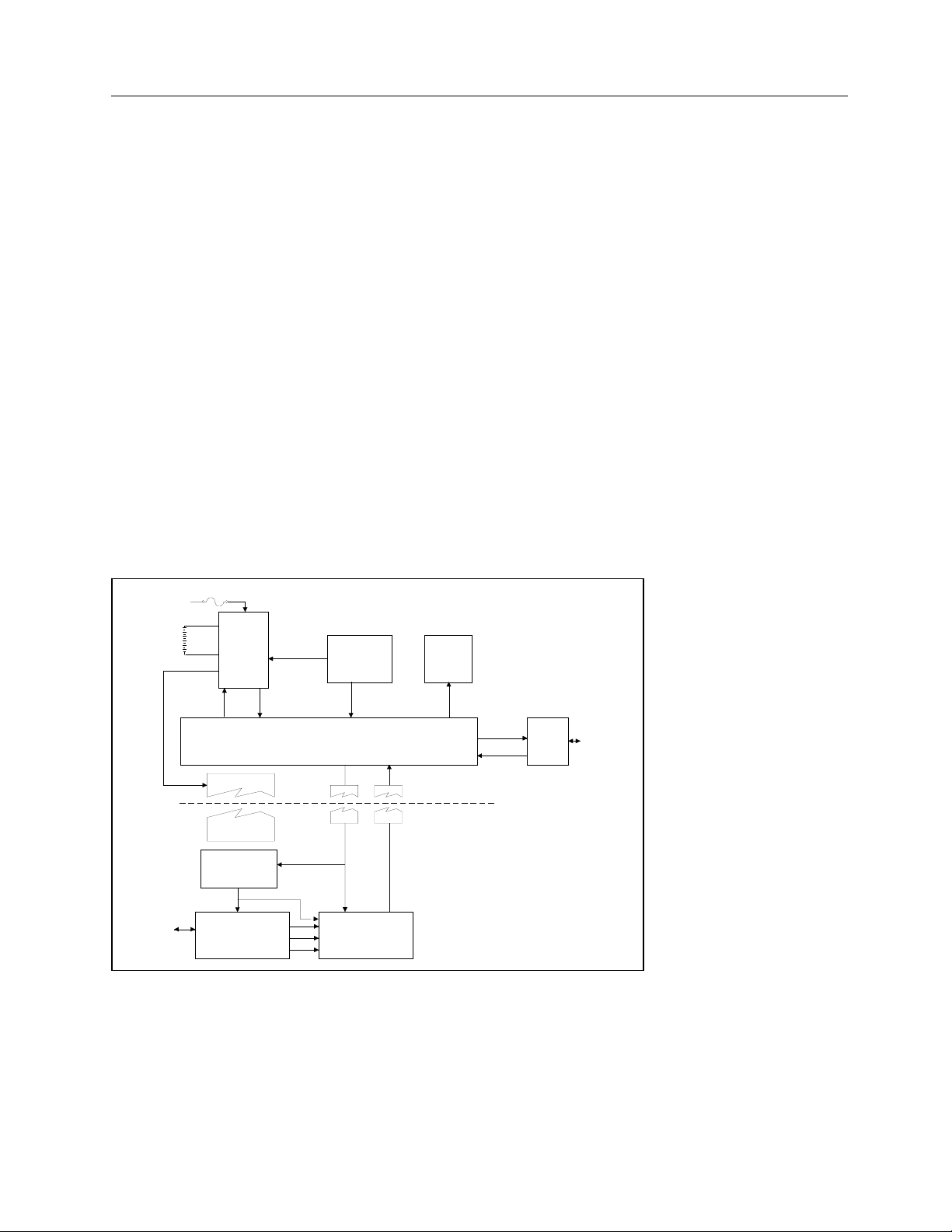
2.2 Functional Description
The Model 35040 Therapy Dosimeter is a portable instrument that measures charge and current.
Calibrated ion chamber factors convert charge and current to directly measure radiation dose and dose
rate in the user specified radiological units. The reading may be corrected for air density by the user
entering ambient temperature and barometric pressure readings. The electronic bias setting is selectable
from the front panel.
Figure 2-1. Hardware Block Diagram of the Model 35040 Therapy Dosimeter
AC Line
POWER
SUPPLY
BATTERY
PACK
FUSE
POWER
SWITCH
CONTACTS
FRONT PANEL
SWITCHES
POWER
CONTROL
BATTERY
STATUS
PROCESSOR
SELECTION
SWITCH
CONTACTS
VFD
DISPLAY
SERIAL
COMM.
PORT
RS-232
COMPUTER
INTERFACE
CONNECTION
HIGH VOLTAGE ISOLATION
ELECTRONIC
BIAS SUPPLY
BIAS
BIAS CONTROL
CONVERSION
CONTROL
CONVERSION
RESULTS
MULTIPLEXER AND
A/D CONVERTER
ELECTROMETER
ION
CHAMBER
CONNECTOR

35040
Operators Manual
2-2
2.2.1 Power Supply
During operation, the instrument may be powered by line voltage in the range of 100 to 240 VAC or from
the internal 6 volt sealed lead acid battery for up to 8 hours. The power supply consists of a high
performance charger that continuously charges the battery whenever the instrument is plugged in. The
charger has three charging stages.
First stage: if the battery is fully discharged, the charger slowly recharges the battery until all cells in the
battery have a minimum charge level on them. The instrument will not operate until the battery has more
than the minimum charge on each cell. The first stage may be more than 18 hours depending on how
severely discharged the battery is.
Second stage: the charger enters a high charge rate that can restore more than 80% of the charge in 2 to
3 hours - even during normal operation. The battery voltage will range from 5.5 to 8.5 volts. The battery
current may be as high as 2.5 amps. After 3 hours of charging, the battery has enough charge for 8
hours of continuous operation.
Third stage: the charger enters a float charge stage that can be used indefinitely to maintain a full charge
on the battery without harm. The battery voltage is approximately 7 volts. The current will range from 0.5
to 0.01 amps. The lower the current, the closer the battery is to full capacity. For additional information
on care of the battery, see Section 3.8.
When operating from batteries, the battery current will be negative. The battery voltage will range from
6.5 volts to 5.4 volts. There are two automatic mechanisms to prevent excessive discharge of the battery.
If the voltage drops below 5.9 volts, a low battery annunciator (LoBat) is displayed on the front panel.
Less than 30 minutes of operating time are left. When the voltage drops to 5.4 volts, the firmware
automatically turns off the instrument. The hardware will turn off the power if the voltage drops below 5.4
volts.
The AC Power Line is fused as it enters the instrument with two fuses. These external fuses may be
replaced by the user (see Section 4.6 for details).
2.2.2 Front Panel
Pressing the power switch, an isolated, momentary-contact switch, once turns the power on. Pressing it
again turns the power off. At least 5 seconds should elapse after turning the power off to let the internal
parts reset before trying to turn power back on. The other keys, a matrix of 8 open contact membrane
switches, are scanned when any key closure is detected. The key code is stored until it is used. The four
line by twenty-character vacuum fluorescent display is easy to read over a wide range of lighting
conditions.
2.2.3 MicroController
A Motorola processor controls the instrument. The operating program is stored in EPROM. RAM is used
for volatile storage. Calibration parameters (gains and offsets) and customization parameters (ion
chamber calibration factors, pressure, and temperature units, bias settings) are stored in EEPROM. Each
time the instrument is turned off, all front panel settings are stored in a small portion of the EEPROM.
The settings are restored when the instrument is turned on.
2.2.4 Serial Communications Port
The serial port is configured as an RS-232C data communications device (DCE) running at 9600 baud, 8
bits, no parity, and 1 stop bit. The protocol uses XON/XOFF handshaking. This port is used for factory
calibration and testing, for calibration, for customization, and for remote control/data acquisition.
Inadvertent changes of the calibration or customization parameters are prevented by use of a three-step
sequence.

Theory of Operation
Functional Description
2
2-3
2.2.5 Electrometer
The electrometer is a single range, resettable, integrating amplifier. The high speed solid state reset is
activated either by the operator pressing the RESET/MEASURE button or automatically when the
instrument detects the end of an exposure. Errors resulting from temperature drift of the components and
from dielectric absorption are dynamically corrected by the controlling firmware.
2.2.6 Bias Supply
The Model 35040 Therapy Dosimeter has a fully regulated electronic bias supply. The user may specify
up to 11 settings within the range -500.0 to +500.0 volts, in any order, during customization of the
instrument. Typical settings are +300.0, +150.0, 0, -150.0, and -300.0 volts, which conform to the
recommendations of the American Association of Physicists in Medicine Task Group 21 (AAPM TG21).
Other locality specific protocols can be accommodated within the 11 settings.
During operation, the bias supply output level is periodically measured by the A/D through a resistive
divider. If the output is more than ± 1.0 volt from the set voltage, an error message (LoBias, or HiBias)
will appear on the display. The bias supply has been designed to drive a capacitive load of less than
5000 pf.
Attaching a larger capacitance may create a
potential shock hazard.
For operator safety, the output of the bias supply is energy and current limited. Before attempting to
connect or disconnect an ion chamber, the operator should either set the bias voltage to 0 volts or turn off
the instrument. Setting the bias voltage to 0 volts pulls the bias to a safe level within one second. The
output of the bias supply is de-energized at power down. De-energizing may take 15 to 30 seconds.
2.2.7 Multiplexer and A/D Converter
The output of the electrometer is sampled at approximately 20 times per second by an analog to digital
converter. The temperature of the electrometer is measured whenever the electrometer is reset. The
program uses the temperature measurement to correct for temperature-induced drift in the electrometer
components. The internal temperature may be different from the ambient temperature, especially during
the battery high charge rate stage.
2.3 Basic Operating Equations
The instrument makes extensive use of the microcontroller’s processing capabilities to directly implement
the operating equations. The variables used in the equations are detailed in the table below. The
equations in this section have measurement units enclosed in square brackets as a reminder of the
required units, e.g. [C] for Coulombs.
CAUTION

35040
Operators Manual
2-4
Table 2-1. Description of Quantities
Quantity Description Units Comments
ADCF
Air Density
Correction
Factor
None
Calculated by instrument and depends on front panel
Temperature and Pressure settings.
QExposure
Charge during
exposure
C
Electrical charge delivered to readout in response to
radiation incident upon detector since the last
exposure.
QAccum
Accumulated
Charge
C
The sum of all charge accumulated due to exposures
since the RESET/MEASURE button was last pressed.
QAccum_previous
Previous
Accumulated
Charge
C
The sum of all accumulated charge not including the
current exposure since the RESET/MEASURE button
was last pressed.
QElectrometer
Electrometer
Charge
C Factory calibrated electrical charge.
Q
Charge C Calibrated electrical charge.
QScaleFactor
Charge Scale
Factor
C / C
Calibrates the charge measured by the electrometer.
Viewed on a Test Function screen.
QOffset
Charge
Leakage
C
The electrical charge measured when no incident
radiation is present.
I
Current A Calibrated electrical current.
IAvg
Average
Current
A
The constant electrical current required to accumulate
charge Q over time TStart to T.
ICCF
Ion Chamber
Calibration
Factor
Ion
Chamber
Calibration
Units
/ A or C
Values are field programmable via Customization
Software.
ILeakage
Leakage
Current
A
The electrical current measured when no incident
radiation is present.
IScaleFactor
Current Scale
Factor
A / A
Calibrates the current. Viewed on a Test Function
screen.
RateMultiplier
Rate Units
Multiplier
s
Specifies the number of seconds the rate divisor is
equal to 1(s), 60(min), 3600(hr).
T
Q Sampling
Time
s The time corresponding to Q and I.
Time
Effective Time
of Exposure
s
The time required to accumulate charge QExposure
with a constant electrical current IAvg.
TOffset
QOffset
Sampling Time
s The time corresponding to QOffset and ILeakage.
QTimed
Timed Charge C
The electrical charge delivered during the timer
interval.
QTimed_Predicted
Predicted
Timed Charge
C
The total amount of timed charge that should be
accumulated at the completion of the timer interval,
based on the observed delivery rate.

Theory of Operation
Basic Operating Equations
2
2-5
Charge and Current Measurements
The instrument’s electrometer charge and current measurements are factory calibrated to a United States
National Institute for Standards and Technology (NIST) traceable standard. Governing regulatory
agencies or best of practice protocols may require that the instrument be calibrated by an independent
calibration agency. The calibration agency may install the correction factors (Q
ScaleFactor
, I
ScaleFactor
) to make
the instrument read out directly as calibrated. These factors are viewable by the operator but may not be
changed or turned off. In almost all cases, the scaling factors will be nearly unity.
[C/C] [C] rScaleFactoerElectromet QQQ ×=
() ( )
() ( )
[A/A] [C/s] rScaleFactoI
iTiT
iQiQ
I ×
⎟
⎟
⎠
⎞
⎜
⎜
⎝
⎛
−−
−−
=
1
1
[s] conversionerelectrometoftimeT =
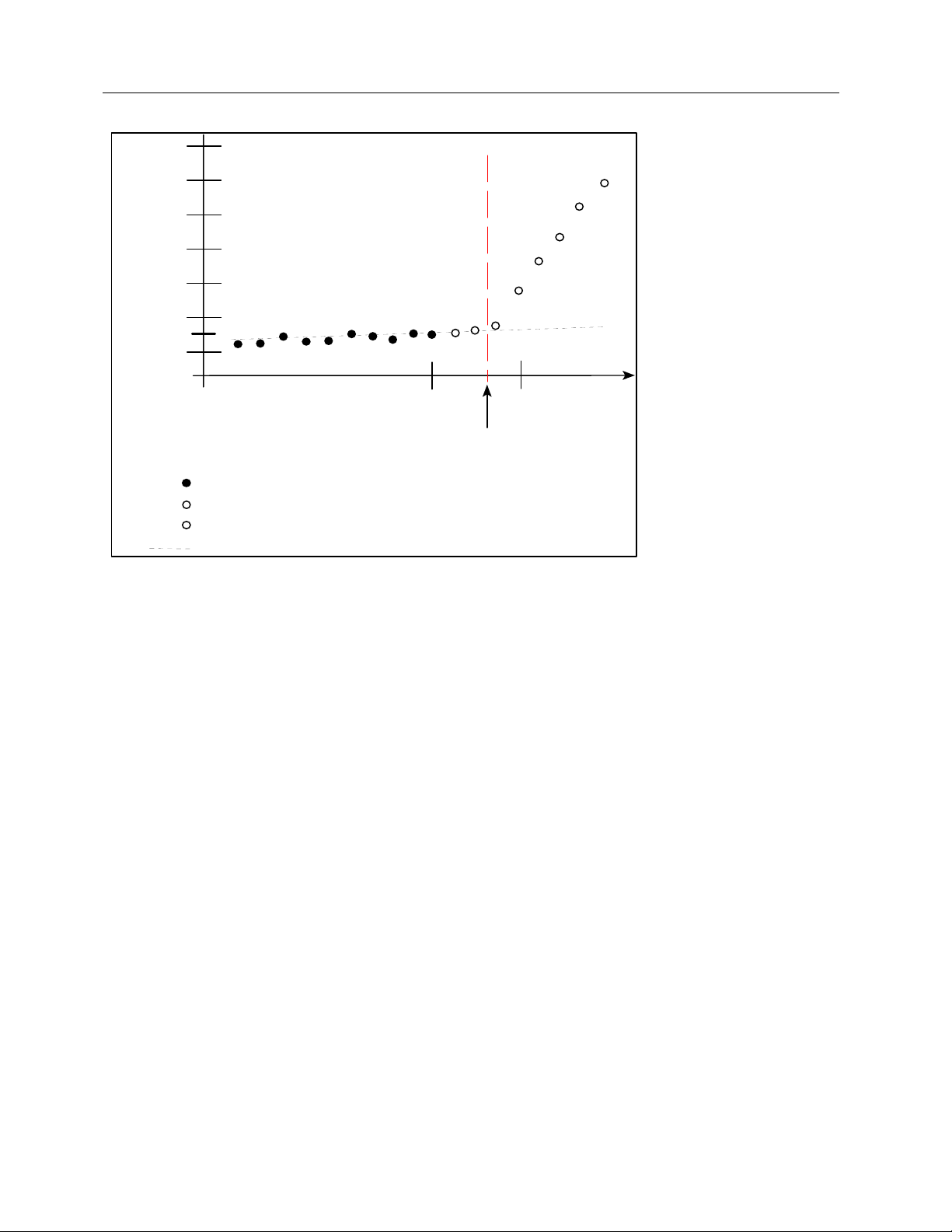
Leakage Measurements
Leakage measurements (Q
Offset
, I
Leakage
and T
Offset
) are only applicable when automatic leakage
compensation is enabled.
The leakage current is defined as the current present between exposures. The displayed leakage current
or dose rate value (3-1/2 digit) is updated at a rate of approximately one time per second and held during
an exposure. Extrapolated charge due to leakage current is nulled from the measurement. In order to do
this, a short-term history of the leakage current is necessary.
When an exposure is not in progress and the absolute value of the current is less than the start threshold,
pressing the RESET/MEASURE button sets the leakage current I
Leakage
to zero and starts the acquisition
of current measurements for determining I
Leakage.
To get the “best” determination of I
Leakage
takes time, at
least 10 seconds. The ion chamber, cables, and instrument should not be disturbed while making the
leakage measurement.
()
[C] OffsetOffset TQQ =
I
I
n
Leakage
n
=
∑
1
[A]
DoseRateLeakage
I
I
CC
F
A
DC
F
RateMultiplie
r
Leakage=×
×
×
[A] [Units
/
C] [s]
T
T
Offset = [s]
35040
Operators Manual
2-6
Figure 2-2. Leakage Current and Start of Exposure
When automatic exposure detection is disabled (start and stop threshold set to 0.0 pA), there is no
correction for extrapolated charge due to leakage current. The dosimeter must be manually reset
between exposures and the leakage current kept as low as possible for best results.
Exposure Charge and Dose
The charge on the electrometer during an exposure is due to the incident radiation plus the charge that
was on the electrometer before the exposure plus the extrapolated charge due to any leakage currents in
the ion chamber, cables, or electrometer. To obtain only the charge due to the exposure, the instrument
employs the following equation:
The exposure charge variable Q
Exposure
is set to zero at the start of an exposure either manually by
pressing the RESET/MEASURE button or automatically if the start and stop thresholds are used. Over
the duration of the exposure, Q
Exposure
and Dose are updated about once a second. The displayed
measurement value (4-1/2 digit) is held following the exposure.
Timed Charge and Dose
This measurement accumulates charge only while the elapsed time is less than or equal to the timer
interval setting. The displayed value is held following the completion of the timer interval.
()()
[s] [s] [A] [C] [C] 12Leakage12Timed TTIQQQ
−
×−−=
ADCFICCFQDose TimedTimed ××= [Units/C] [C]
Time
0
- Charge samples in exposure.
- Extrapolated charge due to leakage current
QOffset
- Charge samples in Leakage.
Charge
- Samples discarded.
TOffset
Start of Exposure
TStart
X
X
X
X
ADCFICCFQDose Exposure ××= [Units/C] [C]
(
)()
[s] [s] [A] [C] [C] OffsetLeakageOffsetExposure TTIQQQ
−
×
−−=

Theory of Operation
Basic Operating Equations
2
2-7
Q
1
represents the next sample of charge at time T
1
following the activation of the timer. Q
2
corresponds to
the interpolated charge at time T
2
, where T
2
is an integral number of seconds that is restricted to times
within the range: T
1
< T
2
≤ (T
1
+ Timer Interval Setting).
Predicted Timed Charge and Dose
This measurement extrapolates the timed charge (Q
Timed
) at the elapsed time (T
Elapsed
) that should be
accumulated at completion of the timer interval (i.e., TimerIntervalSetting) based on the rate of charge
delivery.
[s]
[s]
[C]
valSettingTimerInter
T
Q
Q
Elapsed
Timed
ictedTimed_Pred
×=
ADCFICCFQDose ictedTimed_PredictedTimed_Pred
×
×= [Units/C] [C]
At the conclusion of the timer interval (i.e., T
Elapsed
equals the TimerIntervalSetting), the predicted timed
charge and dose are equal to the predicted timed charge and dose, respectively.
Accumulated Charge and Dose
This measurement accumulates charge across multiple exposures. The displayed value is updated
during the exposure and held between exposures. It is reset to zero when the RESET/MEASURE button
is pressed while viewing a measurement screen.
[C] [C] _ ExposurepreviousAccumAccum QQQ +=
ADCFICCFQDoseAccum Accum
×
×
= [Units/C] [C]
Exposure Current and Rate
The current (3-1/2 digit) and dose rate displayed when the exposure is in progress are updated once per
second. The current and dose rate return to zero after the end of the exposure. The dose rate
measurement is displayed using the selected time base (seconds, minutes, or hours). If the start and
stop thresholds are set to zero, I
Leakage
is zero.
[A] [A] LeakageExposure III −=
[s] [Units/C] [A] = lierRateMultipADCFICCFIDoseRate Exposure
×
×
×
Average Current and Rate
The average current is calculated using the charge accumulated (
Q
/
U
t
) during a portion of the exposure to
eliminate noise effects. The displayed value (4-/1/2 digit) is held following the exposure and reset at the
start of a subsequent exposure.
Q
1
and Q
2
are measured within the exposure at times T
1
and T
2
respectively. T
1
is 1.33 seconds after the
start of exposure. T
2
is 1.33 seconds before the end of exposure (see Figure 2-3). The exposure must be
more than 3 seconds long. I
Avg
is 0 if the exposure is less than 3 seconds.
2.3.1 Setting Thresholds
The instrument has capability to automatically detect the start and end of an exposure when the current
crosses given limits. Using automatic detection eliminates the sag in readings that occur due to leakage
⎟
⎟
⎠
⎞
⎜
⎜
⎝
⎛
−
−
=
[s][s]
[C] [C]
12
12
TT
QQ
I
Avg
[s] [Units/C] [A] = lierRateMultipADCFICCFIgDoseRateAv Avg
×
×
×

35040
Operators Manual
2-8
or dielectric absorption. The start and stop thresholds are set independently, but the stop threshold must
be less than the start threshold. The thresholds are settable in 0.1 pA increments from 0.0 pA to 9.9 pA.
In some test setups, it may be necessary to raise the thresholds to reliably detect an exposure in the
presence of a relatively large leakage current. Since the start threshold determines the minimum dose
rate, it may be necessary to lower the thresholds for some exposures.
The minimum dose rate is
where I[A] is the start threshold setting.
When the start and stop thresholds are set to 0.0 pA, the automatic detection of start and end of exposure
is disabled. This effectively means that the instrument is measuring as if an exposure has been running
continuously. In this mode of operation, leakage current is not measured, the average current is
measured from the last time RESET/MEASURE was pressed, and charge will accumulate due to leakage
current.
Thresholds other than those used by the calibration
agency may render inaccurate measurements.
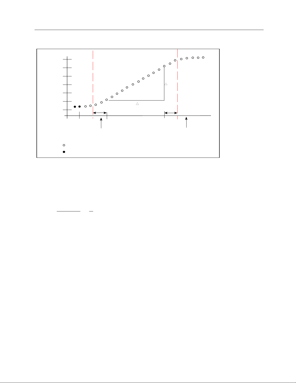
2.3.2 Exposure Time
Historically, the determination of exposure time for
60
Co has involved multiple exposures to eliminate the
effect of the shutter speed. By using the total charge and the average current for the exposure, the
effective exposure time can be determined using a single exposure. If the average current varies by more
than 10% during the exposure, this measurement is considered invalid and will be replaced by “INVALID.”
The effective exposure time is derived from the total charge and the average current. In order to get
enough data points to accurately calculate the time, the exposure must be a minimum of 3 seconds. To
avoid artifacts at the start and end of exposure, the average current is calculated over the interval starting
1 1/3 seconds after the start is detected to 1 1/3 seconds before the end of exposure.
[s] [Units/C] [A] = lierRateMultipADCFICCFIDoseRate
×
××
NOTE
⎟
⎟
⎠
⎞
⎜
⎜
⎝
⎛
−
−
=
[s][s]
[C] [C]
12
12
TT
QQ
I
Avg
⎟
⎟
⎠
⎞
⎜
⎜
⎝
⎛
=
[A]
[C]
AvgI
Q
Time
Theory of Operation
Basic Operating Equations
2
2-9
Figure 2-3. Average Current and Exposure Time
2.3.3 Air Density Correction Factor
The air density correction factor is used to correct dose and dose rate measurements for a vented ion
chamber.
where the pressure “P” is expressed in mmHg, the temperature “T” is in Kelvin, and the calibration
temperature “T
c
” is in Kelvin. The calibration temperature is either 20°C (293.15 K) or 22°C (295.15 K),
depending on that used by the calibration agency when calibrating the ion chamber. The calibration
temperature must be specified during customization. The ADCF is displayed on the bottom line of the Air
Density screen.
When the user has customized the Model 35040 Therapy Dosimeter to use other temperature and
pressure units, the corresponding values entered by the user at the instrument’s front panel are
automatically converted to mmHg and K before use in calculating the ADCF. The equations used for
these conversions are listed below. The abbreviation FSL stands for “from sea level.”
mm Hg = inch Hg x 25.4
mm Hg = 760 x (54,041 - feet FSL) / (54,041 + feetFSL)
mm Hg = 760 x (16,472 - metersFSL) / (16,472 + metersFSL)
mmHg = mbar x 0.75006
mmHg = hPa x 0.75006
K = (5 / 9) x (F - 32) + 273.15
K = C + 273.15
Time
0
- Sampled charge data points in average current.
T2
- Charge data points for leakage.
T1
Charge
Start of Exposure Detected
End of Exposure Detected
1.33s
1.33s
TOffset
T
Q
X
X
X
X
X
X
X
X
X X
X
c
⎟
⎠
⎞
⎜
⎝
⎛
×
⎟
⎠
⎞
⎜
⎝
⎛
=
T
T
P
mmHg
ADCF
760
35040
Operators Manual
2-10
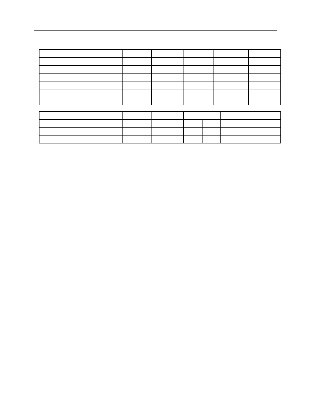
Table 2-2. Air Density Adjustment Ranges and Resolutions
Units Display Minimum Maximum Standard Resolution
% Error
*
inches of mercury inHg 20.55 31.30 29.90 0.05 0.12
millimeters of mercury mmHg 522 795 760 1.0 0.10
altitude in feet ft -1200 10,000 0 25 0.07
altitude in meters m -360 3050 0 10 0.09
millibars mbar 697 1060 1013 1.0 0.07
hectoPascals hPa 697 1060 1013 1.0 0.07
Units Display Minimum Maximum Standard Resolution
% Error
*
Fahrenheit F 32.0 122.0 71.6 68.0 0.5 0.05
Kelvin K 273.0 323.0 295.2 293.2 0.5 0.09
Celsius C 0.0 50.0 22.0 20.0 0.5 0.09
* The “% Error” column indicates the maximum amount of error that can occur due to the step resolution
of the pressure or temperature units.
Operation
Setup
3
3-1
Section 3
Operation
3.1 Setup
Introduction
This section contains set-up and connection procedures for the Model 35040 Therapy Dosimeter.
The instrument is factory calibrated to measure charge (Coulombs) and current (Amperes). It is
recommended that the user customize the Model 35040 Therapy Dosimeter prior to its first use. This
customization may involve selecting the desired ion chamber calibration factor, temperature units,
pressure units, and bias voltages. Procedures for carrying out the customization are covered in Section
3.10.
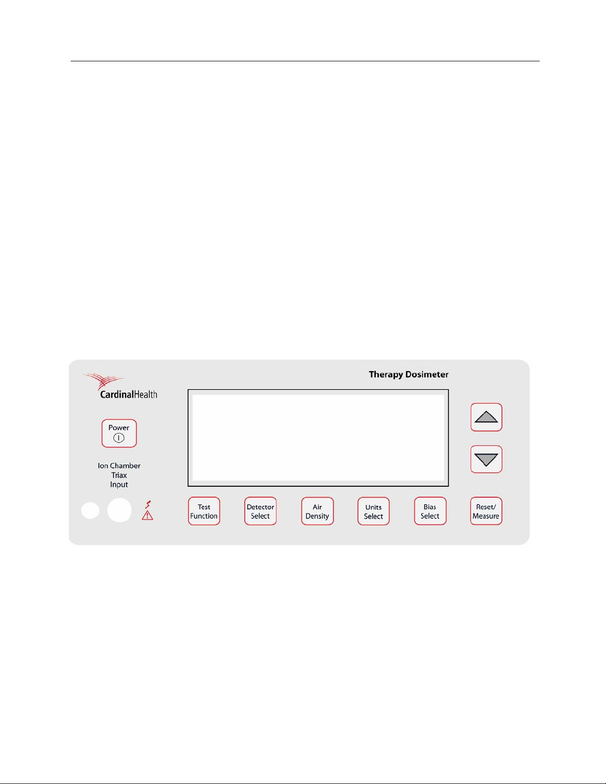
3.2 Front Panel Familiarization
Figure 3-1. The Model 35040 Therapy Dosimeter Front Panel
Triaxial Ion Chamber Input: This input accepts the current line of ion chambers from Fluke Biomedical,
various 0.6 cc, 0.3 cc, and 0.1 cc therapy ion chambers from other manufacturers, and Brachytherapy
well chambers. The front panel ion chamber input is wired in parallel with the rear panel ion chamber
input.
35040
Operators Manual
3-2
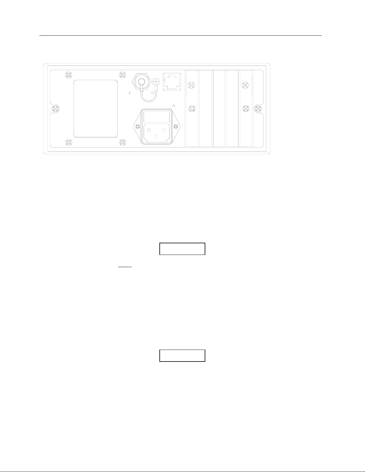
3.3 Rear Panel Familiarization
Figure 3-2. The Model 35040 Therapy Dosimeter Rear Panel
RS-232 Receptacle (RJ-45 Style): The RS-232 Computer Interface is used for computer controlled
factory test, for calibration, for customization, and for remote control/data acquisition.
AC Line Power Receptacle: The AC line input range is 100 - 240 VAC (47 - 63 Hz). AC line voltage
within the specified range has no effect on any dosimeter measurements. The IEC 320/C13 style
receptacle permits worldwide operation by simply changing the line cord.
Triaxial Ion Chamber Input: This input is preferred in semi-permanent setups where the dosimeter is
stationary at the treatment console. The rear triaxial is wired in parallel with front panel input.
Do NOT
attach ion chambers to both the front and
rear connectors at the same time. The signals will
be the summation of the two inputs and may result
in erroneous readings.
3.4 Powering The System
The Model 35040 Therapy Dosimeter may be operated from either line or battery power. The line
receptacle at the rear panel of the Model 35040 Therapy Dosimeter mates with a 3-wire line cord to
provide a connection to line voltage (high, neutral and earth ground).
When powering the Model 35040 Therapy Dosimeter from an
AC line, always use a 3-wire grounding type line cord such as
the one supplied with the dosimeter. In addition, only connect
the Model 35040 Therapy Dosimeter to an AC power outlet
employing a third wire safety ground. Failure to ground the
Model 35040 Therapy Dosimeter may result in personal injury
or death in the event of a short circuit or malfunction.
TRIAX
ION CHAMBER INPUT
RS-232
INTERFACE
COMPUTER
100-240V 50/60 Hz 50VA
!
!
NOTE
WARNING
Operation
Powering the System
3
3-3
The Model 35040 Therapy Dosimeter operates on battery power for eight hours after a full charge. The
dosimeter can be recharged quickly, usually in two to three hours, even during instrument operation. A
low battery annunciator is displayed when 30 minutes or less of operation remains. When the battery
pack is fully discharged, the instrument automatically shuts off and will not operate until AC line power is
connected.
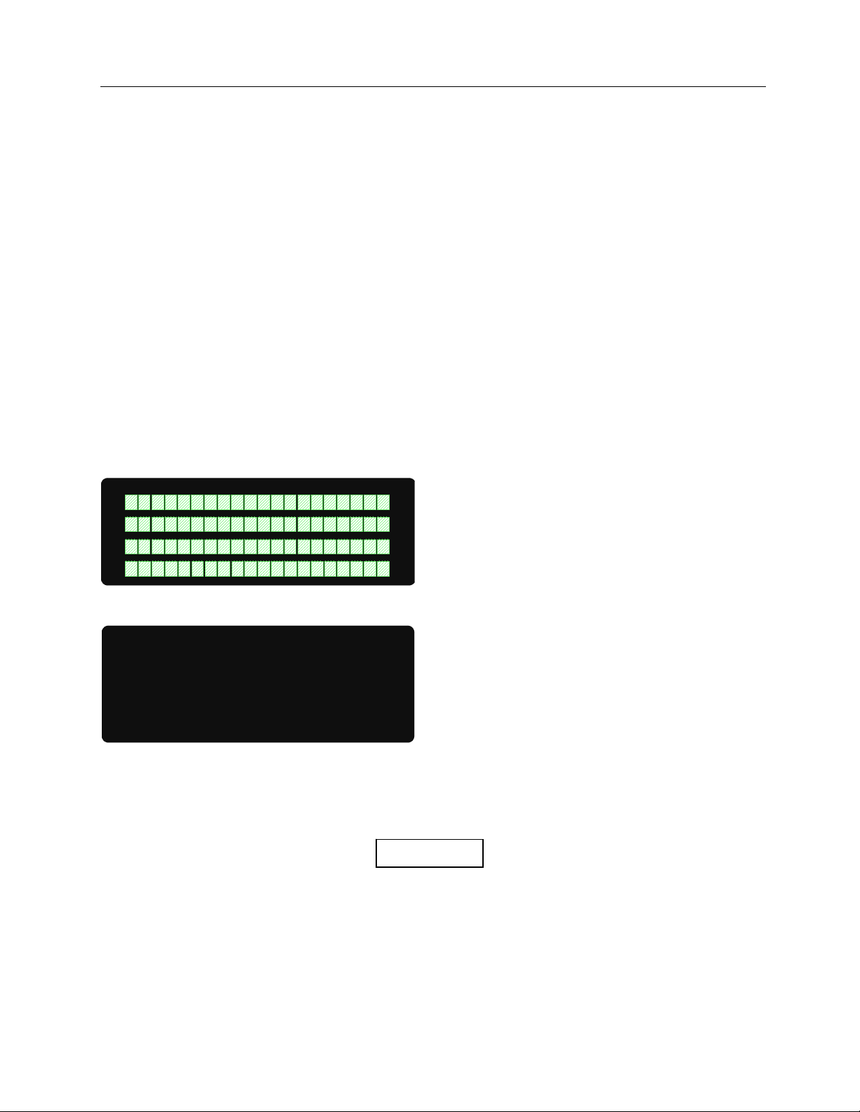
3.5 Power-Up Self-Test and Display Messages
When the instrument is powered up by pressing and releasing the POWER ON/OFF button, the following
sequence of screens will be displayed:
1. The Pixel Test screen lights up all the pixels on the screen (2-10 seconds).
2. Calibration information showing the calibration agency and the calibration date (2 seconds).
3. Firmware revision date (2 seconds).
4. Instrument bias, leakage, and battery levels.
During this opening screen sequence, pressing a front panel button will have no effect. The instrument
bias, leakage, and battery level screen will be the last screen displayed as shown below. At the
completion of the sequence, other functions may be selected.
See Section 3.9.4 for an explanation of the contents of each screen.
Figure 3-3. The Pixel Test Screen
Figure 3-4. The Bias, Leakage, and Battery Voltage and Current
3.6 Ion Chamber Connector
Never connect a coaxial BNC type cable to the
Model 35040 Therapy Dosimeter’s triaxial ion
chamber input connectors. Doing so will damage
the ion chamber input connector.
Leakage: 0.001 pA
ADC
IC Bias: 300.0V CEP
Batt: 6.8 V +0.10 A
CAUTION

35040
Operators Manual
3-4
Mating and unmating to this connector (or to the
other end of a cable already connected to it) should
be done only when the bias is set to 0 volts, or
when the instrument power is turned off. The
central pin and inner shield shell of the triaxial
connector are operated at the bias voltage above
the outer shell and instrument case. Although the
bias potential is energy and current limited, care
should be taken to avoid unnecessary and possibly
hazardous shocks.
The connector is a triaxial female with dust cap and chain. It connects to any low-noise triaxial male
cables. The NE 2571A 0.6 cc Farmer Ion Chamber and other ion chambers may be operated with the
Model 35040 Therapy Dosimeter.
The connector is mounted to avoid contaminating spills and dust. Putting its dust cap in place whenever
a cable is not connected will help assure long service with minimum leakage problems.
3.7 Basic Measurement Techniques
3.7.1 General Considerations
The dosimeter must be placed on a solid, non-vibrating surface. Both the dosimeter and the operator
must be outside the radiation field. Any cable movement will induce a current that may interfere with
proper measurements. You should wait ten seconds or more after moving the ion chamber, triaxial cable,
or disturbing another part of the high impedance circuit before taking a measurement.
3.7.2 Making Non-Timed Exposure Measurements
With Automatic Leakage Compensation Disabled
The instrument must be manually reset before each exposure when automatic leakage compensation is
disabled.
Procedure
• Hold RESET/MEASURE for one second just before making the exposure to reset the instrument.
Note that the instrument displays the “Rst” annunciator while the hardware is being reset.
• Wait for the reset to complete.
• Make the exposure.
The exposure measurements will be displayed but may drift due to leakage. Repeat this sequence for
every exposure.
With Automatic Leakage Compensation Enabled
In addition to compensating measurements for leakage, the instrument holds the exposure
measurements and automatically resets after each exposure when automatic leakage compensation is
enabled.
WARNING

Operation
Basic Measurement Techniques
3
3-5
Procedure:
• The annunciator line on the Measurement screen displays "WAIT System Not RDY" while the
instrument is acquiring the minimum number of samples required for leakage compensation. Wait
for this message to disappear.
• Wait for the leakage current to return to the nominal value.
• Make the exposure.
When the instrument senses that the exposure is over, it displays and holds the exposure measurements
and then resets the electrometer (refer to Section 3.9.7 for information on configuring the start and stop
thresholds). The exposure measurements are displayed until either the RESET/MEASURE button is held
for one second, the bias voltage or threshold changed, or another exposure is started.
3.7.3 Making Timed Exposure Measurements
The timer is available when any of the measurement displays contains a timed measurement. Refer to
Section 3.10 for information on customizing measurement displays.
Timer Setup
Procedure:
• Use the TEST FUNCTION button, along with the UP and DOWN arrows to display the Timer Setup
screen.
• To modify the timer setup, press the TEST FUNCTION button to display the "f" cursor at the timer
interval field and use the UP and DOWN arrows to select a timer interval from the programmed list.
(Refer to Section 3.10 for information on how to program the interval list.)
• Press the TEST FUNCTION button to advance the "f" cursor to the timer count mode field and use
the UP and DOWN arrow keys to select up (UP) or down (DOWN) for the count mode.
• Press the TEST FUNCTION button to advance the "f" cursor to the timer decimal places field and
use the UP and DOWN arrow keys to select zero (0) or one (1).
• Press the TEST FUNCTION button to hide the cursor and save any changes. Proceed to using the
timer, which is discussed next.
Timer Use
Procedure:
• Press the RESET/MEASURE button to show the Measurement screen if it is not displayed.
• To start or manually stop the timer, press the RESET/MEASURE button while the instrument is
updating other exposure measurements (e.g., charge and current). The instrument displays the
“Tmr” annunciator when the timer is running.
The instrument will not permit the timer to be
started while leakage is being measured.
• Upon completion of the timer interval or if the instrument senses the exposure is over (applicable
when automatic leakage compensation is enabled), the instrument ceases updating the timed
measurements.
NOTE
 Loading...