


657
www.Fisher.com
D100307X012
Type 657 Diaphragm Actuators
Size 80 and 100
Contents
Introduction 2. . . . . . . . . . . . . . . . . . . . . . . . . . . . . . .
Scope of Manual 2. . . . . . . . . . . . . . . . . . . . . . . . .
Description 2. . . . . . . . . . . . . . . . . . . . . . . . . . . . . .
Specifications 2. . . . . . . . . . . . . . . . . . . . . . . . . . . .
Installation 3. . . . . . . . . . . . . . . . . . . . . . . . . . . . . . . .
Actuator Mounting 3. . . . . . . . . . . . . . . . . . . . . . . .
Loading Connection 3. . . . . . . . . . . . . . . . . . . . .
Adjustments 4. . . . . . . . . . . . . . . . . . . . . . . . . . . . . . .
Travel 4. . . . . . . . . . . . . . . . . . . . . . . . . . . . . . . . . . .
Spring 4. . . . . . . . . . . . . . . . . . . . . . . . . . . . . . . . . . .
Size 80 4. . . . . . . . . . . . . . . . . . . . . . . . . . . . . . . . .
Size 100 4. . . . . . . . . . . . . . . . . . . . . . . . . . . . . . .
Maintenance 5. . . . . . . . . . . . . . . . . . . . . . . . . . . . . .
Actuator 6. . . . . . . . . . . . . . . . . . . . . . . . . . . . . . . . .
Size 80 Disassembly 6. . . . . . . . . . . . . . . . . . . . .
Size 80 Assembly 7. . . . . . . . . . . . . . . . . . . . . . .
Size 100 Disassembly 8. . . . . . . . . . . . . . . . . . . .
Size 100 Assembly 9. . . . . . . . . . . . . . . . . . . . . .
Size 80 Side-Mounted Handwheel 10. . . . . . . . .
Disassembly 10. . . . . . . . . . . . . . . . . . . . . . . . . . .
Assembly 10. . . . . . . . . . . . . . . . . . . . . . . . . . . . . .
Size 80 Hydraulic Snubber 11. . . . . . . . . . . . . . . .
Size 80 Top-Mounted Handwheel
(Adjustable Up Travel Stop) 11. . . . . . . . . . . .
Disassembly 11. . . . . . . . . . . . . . . . . . . . . . . . . . .
Assembly 11. . . . . . . . . . . . . . . . . . . . . . . . . . . . . .
Size 100 Top-Mounted Handwheel
(Adjustable Up Travel Stop) 12. . . . . . . . . . . .
Disassembly 12. . . . . . . . . . . . . . . . . . . . . . . . . . .
Assembly 12. . . . . . . . . . . . . . . . . . . . . . . . . . . . . .
Parts Ordering 13. . . . . . . . . . . . . . . . . . . . . . . . . . . .
Parts List 13. . . . . . . . . . . . . . . . . . . . . . . . . . . . . . . .
Note
Neither Emersonr, Emerson Process
Managementt, Fisherr, nor any of
their affiliated entities assumes
responsibility for the selection, use
and maintenance of any product.
Responsibility for the selection, use,
and maintenance of any product
remains with the purchaser and
end-user.
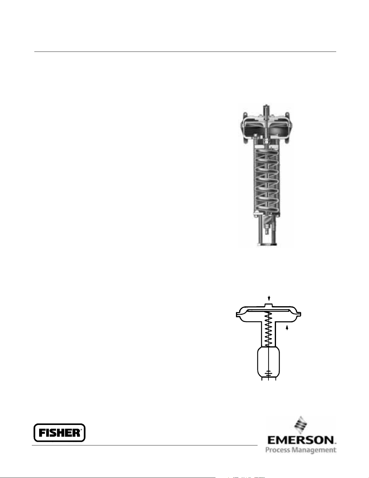
Figure 1. Sectional view of Type 657 Size 100 Actuator
W0366-1 / IL
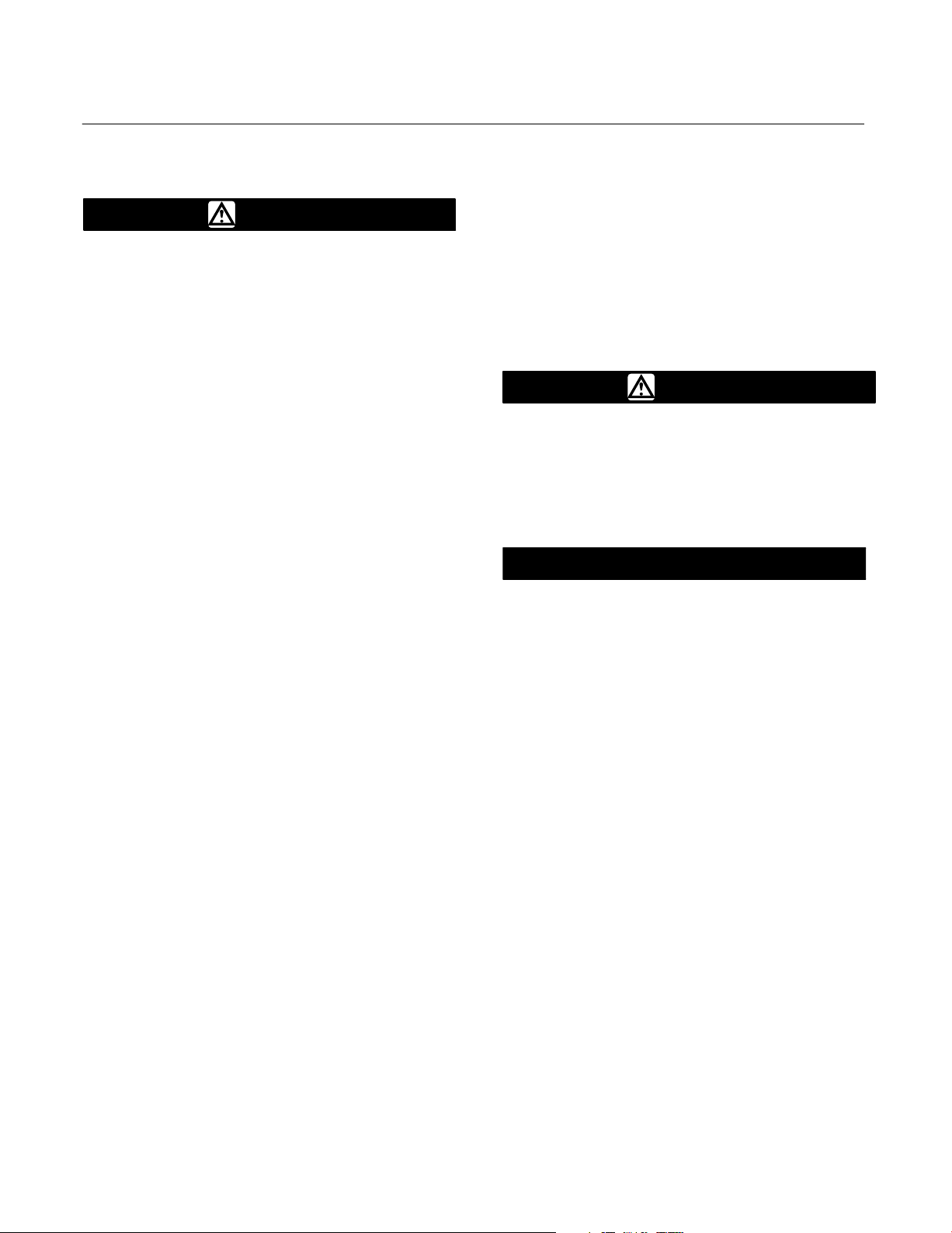
Figure 2. Schematic Representation of Type 657 Actuator
SPRING
LIFTS
AIR PUSHES
STEM DOWN
AF3833-A
A0792-2/IL
Instruction Manual
Form 1909
August 2006
657 Size 80 and 100 Actuators

657 Size 80 and 100 Actuators
Instruction Manual
Form 1909
August 2006
2
Table 1. Specifications
SPECIFICATIONS
ACTUATOR SIZE
80 100
Nominal Effective Diaphragm Area
cm
2
1761 2902
inch
2
273 450
Yoke Boss Diameters
mm 127 127 178
inch 5 5H
(1)
7
Acceptable Valve Stem Diameters
mm 25.4 or 31.8 31.8 50.8
inch 1 or 1-1/4 1-1/4 2
Maximum Allowable Output Thrust
N 62,942 200,170
lb 14,150
(2)
45,000
Maximum Travel
mm 76 102
inch 3 4
Maximum Casing Pressure for Actuator
Sizing
(3)
Cast Iron Steel
bar 3.4 4.9 6.9
psig 50 70 100
Maximum Diaphragm Casing Pressure
(3)(4)
Cast Iron Steel
bar 4.1 5.5 7.9
psig 60 80 11 5
Material Temperature Capabilities
_C
−40 to 82
_F
−40 to 180
Pressure Connections 1/4 inch NPT female
Approximate Weights Without Handwheel
kg 234 346
lb 515 762
1. Heavy actuator-to-bonnet bolting.
2. 88,075 N (19,800 lb) for steel construction.
3. Maximum diaphragm casing pressure must not be exceeded and must not produce a force on the actuator stem greater than the maximum allowable actuator output thrust or the
maximum allowable valve stem force. (If you have any questions on allowable valve stem force, contact your Emerson Process Management sales office.)
4. This maximum casing pressure is not to be used for normal operating pressure. Its purpose is to allow for typical regulator supply settings and/or relief valve tolerances.
Introduction
Scope of Manual
This instruction manual provides information on
installation, adjustment, maintenance, and parts
ordering for the Type 657 actuator in sizes 80 and
100. Refer to separate instruction manuals for
information about other equipment and accessories
used with these actuators.
No person may install, operate, or maintain Type
657 actuators without first D being fully trained and
qualified in valve, actuator, and accessory
installation, operation, and maintenance, and D
carefully reading and understanding the contents of
this manual. If you have any questions about these
instructions, contact your Emerson Process
Management sales office before proceeding.
Description
The Type 657 actuator (figure 1) is a direct-acting,
spring-opposed diaphragm actuator used for
automatic operation of control valves. The actuator
positions the valve plug in response to varying
pneumatic loading pressure on the diaphragm.
Figure 2 shows the operation of these actuators.
A Type 657 actuator can be furnished with either a
top-mounted or side-mounted (size 80 only)
handwheel assembly. A top-mounted handwheel
assembly is normally used as an adjustable-up
travel stop. The size 100 top-mounted handwheel
may be used as an auxiliary manual actuator. A
side-mounted handwheel assembly is normally used
as an auxiliary manual actuator.
Specifications
Refer to table 1 for specifications of the Type 657
actuator. See the actuator nameplate for information
about a specific actuator.
657 Size 80 and 100 Actuators
Instruction Manual
Form 1909
August 2006
3
Installation
WARNING
To avoid personal injury or parts
damage, do not exceed the Maximum
Diaphragm Casing Pressure listed in
table 1. The Maximum Diaphragm
Casing Pressure must not produce a
force on the actuator stem greater than
the maximum allowable actuator
output thrust or the maximum
allowable stem load.
Always wear protective gloves,
clothing, and eyewear when
performing any installation operations
to avoid personal injury.
Check with your process or safety
engineer for any additional measures
that must be taken to protect against
process media.
If installing into an existing
application, also refer to the WARNING
at the beginning of the Maintenance
section in this instruction manual.
When an actuator and valve body are shipped
together, the actuator is normally mounted on the
valve. Follow the valve body instructions when
installing the control valve in the pipeline. If the
actuator is shipped separately or if it is necessary to
mount the actuator on the valve, perform the
Actuator Mounting procedures as described below.
For information on mounting valve positioners, refer
to the appropriate valve positioner instruction
manual.
Actuator Mounting
1. To permit adjustment of the actuator spring, the
size 100 actuator must be installed in a vertical
position above the valve body. Mount the actuator
on the valve bonnet. Insert the cap screws, and
tighten the hex nuts, securing the actuator to the
bonnet.
2. Screw valve stem locknuts (key 16, figure 4) all
the way onto valve stem thread.
3. Connect an air supply to the diaphragm casing.
4. For push-down-to-close valves, be sure the valve
plug is on its seat. Apply pressure to ensure that the
actuator stem is fully extended. Reduce actuator
loading pressure to retract the stem approximately
3.2 mm (1/8-inch).
5. For push-down-to-open valves, move valve plug
to closed position. On large body sizes, this may
require the use of a pry bar inserted through the
body line opening. If the body is installed in a
pipeline, the bottom flange (if one is used) can be
removed and the valve plug pushed to the seat from
the bottom opening. Pressure the actuator to move
the stem out 3.2 mm (1/8-inch).
WARNING
To avoid personal injury due to the
sudden uncontrolled movement of
parts, do not loosen the stem
connector cap screws when the stem
connector has spring or loading
pressure force applied to it.
CAUTION
Incomplete engagement of both valve
stem and actuator stem in the stem
connector can result in stripped
threads or improper operation. Be sure
that the length of each stem clamped
in the stem connector is equal to or
greater than the diameter of that stem.
6. Clamp the actuator and valve plug stems
between the two stem connector halves (key 26,
figure 4). Insert and tighten the stem connector cap
screws.
7. Thread the stem locknuts against the stem
connector.
8. Align the travel indicator scale (key 18, figures 4
and 5) to show valve position.
Loading Connection
1. Connect the loading pressure piping to the
connection in the top of the diaphragm casing.
2. Remove the 1/4-inch bushing (key 33, figure 4
and key 120, figure 5) to increase connection size, if
necessary. The connection can be made with either
piping or tubing.
3. Keep the length of tubing or piping as short as
possible to avoid transmission lag in the control
signal. If an accessory (such as a volume booster or
valve positioner) is used, be sure that the accessory

657 Size 80 and 100 Actuators
Instruction Manual
Form 1909
August 2006
4
is properly connected to the actuator. Refer to the
positioner instruction manual as necessary.
4. Cycle the actuator several times to check that the
valve stem travel is correct and that the travel occurs
when the correct pressure range is applied to the
diaphragm.
5. If valve stem travel is incorrect, refer to the Travel
procedure in the Adjustments section.
6. If the pressure range is incorrect, refer to the
Spring procedure in the Adjustments section.
Adjustments
Travel
Make travel adjustments when the motion observed
during actuator travel is different from the travel
stamped on the actuator nameplate. If the Actuator
Mounting procedure was followed correctly, this
adjustment should not be necessary.
When adjusting travel of a reverse-acting
(push-down-to-open) valve, apply a slight pressure
on the actuator diaphragm. This moves the valve
plug off the seat, reducing the chance of damaging
the valve plug or seat during adjustments.
1. Back the stem locknuts away from the stem
connector, and slightly loosen the stem connector
cap screws.
CAUTION
Do not use wrenches or other tools
directly on the valve stem. Damage to
the stem surface and subsequent
damage to the valve packing may
result.
2. Tighten the locknuts together, using a wrench,
then screw the valve stem either into the stem
connector to lengthen travel or out of the stem
connector to shorten travel.
3. Cycle the actuator to check the travel. If actual
travel is not equal to the specified travel, adjust and
check travel until correct. Tighten the stem
connector cap screws when correct travel is
obtained.
4. Raise the travel indicator disk by threading the
stem locknuts against the stem connector.
Spring
Make spring adjustments when the loading pressure
range applied to achieve specified travel is not equal
to the pressure range stamped on the actuator
nameplate. Refer to the Bench Set pressure range
on the nameplate when the valve contains no
pressure and the packing is loosely inserted in the
bonnet. Refer to the Max. Allow. Supply on the
nameplate when the valve is controlling the specified
pressure drop and the packing is tightened to stop
leaks around the stem.
Monitor loading pressure carefully when making
adjustments. Do not exceed the pressure
specifications of either the loading regulator or the
actuator casings.
Each actuator spring has a fixed pressure span.
Changing the spring compression shifts the span up
or down to make valve travel coincide with the
loading pressure range.
Size 80
Remove cover band (key 60, figure 4), insert a rod of
approximately 12.7 mm (1/2-inch) diameter into a
hole in the adjusting screw (key 12, figure 4), and
rotate the adjusting screw with the rod. Rotating the
screw from left to right will increase the loading
pressure required to start actuator stem travel;
opposite rotation will decrease the pressure required
to start travel.
Size 100
CAUTION
The actuator must be in the vertical
position when adjusting spring to
avoid damage to thrust bearing (key
35, figure 5) and to properly position
spacers required for adjustment.
Remove the shroud plate (key 107, figure 5), and
loosen the jam nut (key 115, figure 5).
For small spring forces, adjustments can be made
by rotating the adjusting nut (key 114, figure 5).
Clockwise rotation (when viewed from diaphragm
casings) of the adjusting nut will increase the loading
pressure required to start actuator stem travel, and
counterclockwise rotation will decrease the pressure
required to start travel. Tighten the jam nut when
adjustment is complete.
657 Size 80 and 100 Actuators
Instruction Manual
Form 1909
August 2006
5
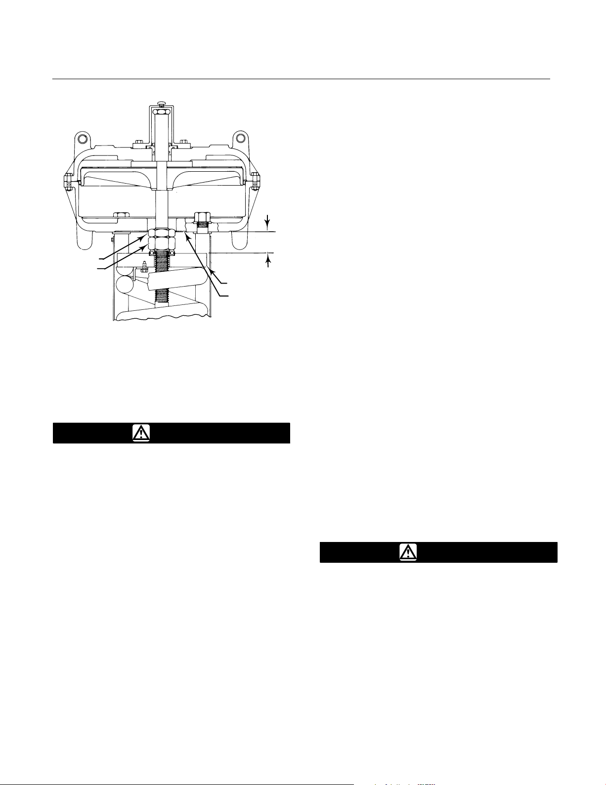
Figure 3. Dimension B for Spring Adjustment
LOWER
DIAPHRAGM
CASING
SPRING SEAT
JAM NUT
ADJUSTING
NUT
A0950-1 / IL
B
For high spring forces, it is necessary to use spacers
between the lower diaphragm casing and the spring
seat to isolate spring force from the adjusting nut.
WARNING
To avoid personal injury from the
compressed actuator spring snapping
back to its original length, make and
use the spacers by following the
instructions in the steps below.
To avoid personal injury, keep hands
and tools away from the spring and
spring seat as instructed in the
following procedure.
1. It is recommended that three spacers be made
of 3-inch schedule 80 pipe cut to the appropriate
length specified in step 2. If other than the
recommended material is to be used, be certain that
the spacers are capable of withstanding the spring
force involved. The spacers must be of equal length
with ends cut squarely.
2. Measure dimension B as shown in figure 3. Cut
length of spacers as follows:
a. If it is desired to decrease spring compression,
make the spacers approximately 4.8 mm
(3/16-inch) longer than dimension B.
b. If it is desired to increase spring compression,
make the spacers approximately 4.8 mm
(3/16-inch) shorter than either dimension B plus
the amount of adjustment required or dimension
B plus valve travel, whichever is less.
3. Whenever the total amount of adjustment
required is greater than valve travel, the adjustment
must be made in two or more steps, and the amount
of adjustment taken in each step must be less than
valve travel.
4. Pressure the actuator to attain full travel.
Cautiously insert the spacers at equal intervals
around the spring seat (key 11, figure 5). The
spacers must be seated squarely when in use or
they may slip out of position. Keeping hands and
tools away from the spring and spring seat, slowly
decrease loading pressure until the spring force
holds the spacers firmly between the spring seat and
lower diaphragm casing (key 5, figure 5).
5. Loosen the jam nut. The adjusting nut can now
be rotated clockwise (when viewed from the
diaphragm casings) to increase the loading pressure
required to start actuator stem travel or
counterclockwise to decrease the pressure required
to start travel.
6. Pressure the actuator to move the spring seat
away from the spacers, and carefully remove the
spacers.
7. If the total adjustment required was greater than
valve travel, repeat the procedure. It will be
necessary to make new spacers using the new
dimension B and the remaining adjustment required
or valve travel, whichever is less. Tighten the jam
nut when adjustment is complete.
Maintenance
WARNING
Avoid personal injury or property
damage from sudden release of
process pressure or bursting of parts.
Before performing any maintenance
operations:
D Always wear protective gloves,
clothing, and eyewear when
performing any maintenance
operations to avoid personal injury.
D Disconnect any operating lines
providing air pressure, electric power,
or a control signal to the actuator. Be

657 Size 80 and 100 Actuators
Instruction Manual
Form 1909
August 2006
6
sure the actuator cannot suddenly
open or close the valve.
D Use bypass valves or completely
shut off the process to isolate the
valve from process pressure. Relieve
process pressure from both sides of
the valve. Drain the process media
from both sides of the valve.
D Vent the power actuator loading
pressure and relieve any actuator
spring precompression.
D Use lock-out procedures to be
sure that the above measures stay in
effect while you work on the
equipment.
D The valve packing box may
contain process fluids that are
pressurized, even when the valve has
been removed from the pipeline.
Process fluids may spray out under
pressure when removing the packing
hardware or packing rings, or when
loosening the packing box pipe plug.
D Check with your process or safety
engineer for any additional measures
that must be taken to protect against
process media.
The maintenance instructions are divided into four
sections: actuator (sizes 80 and 100); side-mounted
handwheel assembly (manual operator); hydraulic
snubber; and top-mounted handwheel assembly
(adjustable-up travel stop).
Actuator
This procedure describes how the actuator can be
completely disassembled and assembled. When
inspection or repairs are required, disassemble only
those parts necessary to accomplish the job; then,
start the assembly at the appropriate step.
Key numbers refer to figure 4 for size 80 actuators
and figure 5 for size 100 actuators.
Size 80 Disassembly
1. Bypass the control valve. Reduce the loading
pressure to atmospheric, and remove the tubing or
piping from the top of the diaphragm casing (key 1).
WARNING
To avoid personal injury from the
precompressed spring force thrusting
the upper diaphragm casing (key 1)
away from the actuator, relieve spring
compression (step 2, below), and
carefully remove casing cap screws
(key 22) (step 4, below).
2. Remove cover band (key 60). Insert a rod of
approximately 12.7 mm (1/2-inch) diameter into a
hole in the adjusting screw (key 12), and rotate the
adjusting screw from right to left until spring
compression is relieved. If the actuator has a
handwheel, rotate it counterclockwise, relieving all
spring compression.
3. If necessary, the entire actuator may be removed
from the valve body by unscrewing two cap screws
from stem connector (key 26) and removing
actuator-to-bonnet bolting.
4. Unscrew diaphragm casing cap screws and nuts
(keys 22 and 23), and lift off upper diaphragm casing
(key 1).
5. Remove the molded diaphragm (key 2).
6. For actuators without snubber, remove
diaphragm plate and stem (keys 4 and 10) as an
assembly. This assembly can be broken down
further, if necessary, by removing the cap screw
(key 3).
7. For actuators with snubber (see figure 7),
unscrew cap screw (key 3), and remove diaphragm
plate (key 4). Remove stem connector (key 26).
Unscrew cap screws (key 85), and remove cylinder
assembly (key 74) and attached stem and upper
seat (keys 10 and 90) from actuator.
To disassemble snubber:
a. Unscrew stem from piston/piston rod
assembly (key 27).
b. Remove retaining rings, cylinder heads, and
piston/piston rod assembly (keys 76, 75, and 27).
Replace packing and O-rings (keys 103, 104, 77
and 105) as required.
8. Remove actuator spring, upper sleeve, and
spring seat (keys 6, 34 and 11).
 Loading...