


PVO-300

POWER VENTER SYSTEM
Model: PVO-300, PVO-600
Included is one ETL and cETL listed Power Venter to be used primarily with a
single 120VAC controlled oil fired furnace, boiler, or water heater. The PVO
may be used to common vent multiple appliances with the addition of a Control
Kit. Please consult Field Control’s Technical Support for other options.
TYPICAL VENTING SYSTEM COMPONENTS
One PVO Series Power Venter with pre-wired controls; adjustable post
purge relay timer, adjustable draft proving switch, direct access terminal
blocks, and piping tee for multiple appliance systems.
• Side Wall Vent Hood (Not included) • Spill Switches (Not included)
• CK-Series Control Kit for multiple appliance venting (Not Included)
CONTENTS PAGE
Unit Specifications 2
System Operation 2
Power Venter Sizing 3
Installation Safety Instructions 4
Installation of Power Venter 5
General Wiring Instructions 5-6
Airflow Adjustments 7
Pressure Switch Adjustments 7
Post Purge Timer Adjustments 7
Multiple Appliance Systems 7
General Installation Inspection 8
Maintenance 8
Replacement Parts List 9
Venting System Operational Information 10
Installation Information 10
This device MUST be installed by a qualified agency in accordance with the manufacturers installation
instructions.
The definition of a qualified agency is: any i ndividual, fir m, corporation or compa ny which eith er in pers on or through a repr esentative is
engaged in, and is responsible for, the installation and operation of gas ap pliances, who is experienced in such work, familiar with all
the precautions required, and has complied with the requirements of the authority having jurisdiction.
DO NOT DESTROY
THESE INSTRUCTIONS MUST REMAIN WITH EQUIPMENT
2630 Airport Road · Kinston, NC 28504
Phone: 252-522-3031· Fax: 252-522-0214
www.fieldcontrols.com

UNIT SPECIFICATIONS
(See Table 1 and Figure 1)
Table 1
UNIT DIMENSIONS (INCHES)
MODEL “H” “W” “D” I/O*
PVO-300
PVO-600
7.50 9.25 7.00 4/4
8.75 9.75 8.50 4/4
*
Inlet and outlet diameter.
ELECTRICAL RATINGS
MODEL VAC Hz RPM WATT AMP TP**
PVO-300
PVO-600
120 60 3000 145 2.1 YES
120 60 3000 167 1.5 YES
**
Thermally protected motor.
Figure 1
SIDEWALL VENT HOODS (Model SWH-1)
Sidewall vent hoods are available in the following sizes. The vent hood should be chosen that matches the outlet size of
the Power Venter. (See Figure 2) NOTE: When using different sizes consider reducers and specific size pipe when
determining equivalent length of vent pipe.
SWH-1-3 - 3 inch
SWH-1-4 - 4 inch
SWH-1-5 - 5 inch
SWH-1-6 - 6 inch
SWH-1-8 - 8 inch
Figure 2
CONTROL KITS
The following Control Kits can be used to common vent multiple appliances with on PVO unit:
CK-61: For operation with all 120VAC oil-fired systems. Includes draft proving switch, adjustable electronic
post purge timer, RJR isolation relay, and WMO-1 secondary safety switch.
CK-62: Same as CK-61, except has thermally activated post purge.
CK-63: For operation with all 120VAC oil-fired systems. Includes draft proving switch, adjustable electronic
post purge timer, and WMO-1 secondary safety switch.
SYSTEM OPERATION
1. The thermostat (wall thermostat, or aquastat) calls for heat and energizes a relay which activates the power venter.
After the venter motor has come up to speed, the pressure switch closes. This completes the circuit to the burner and
allows the burner to fire.
2. After the heating requirement has been satisfied, the thermostat circuit will open and de-activate the burner and power
venter circuit.
3. The power venter continues to operate for a period of time after the burner has shut off to purge remaining flue gases.
Page 2
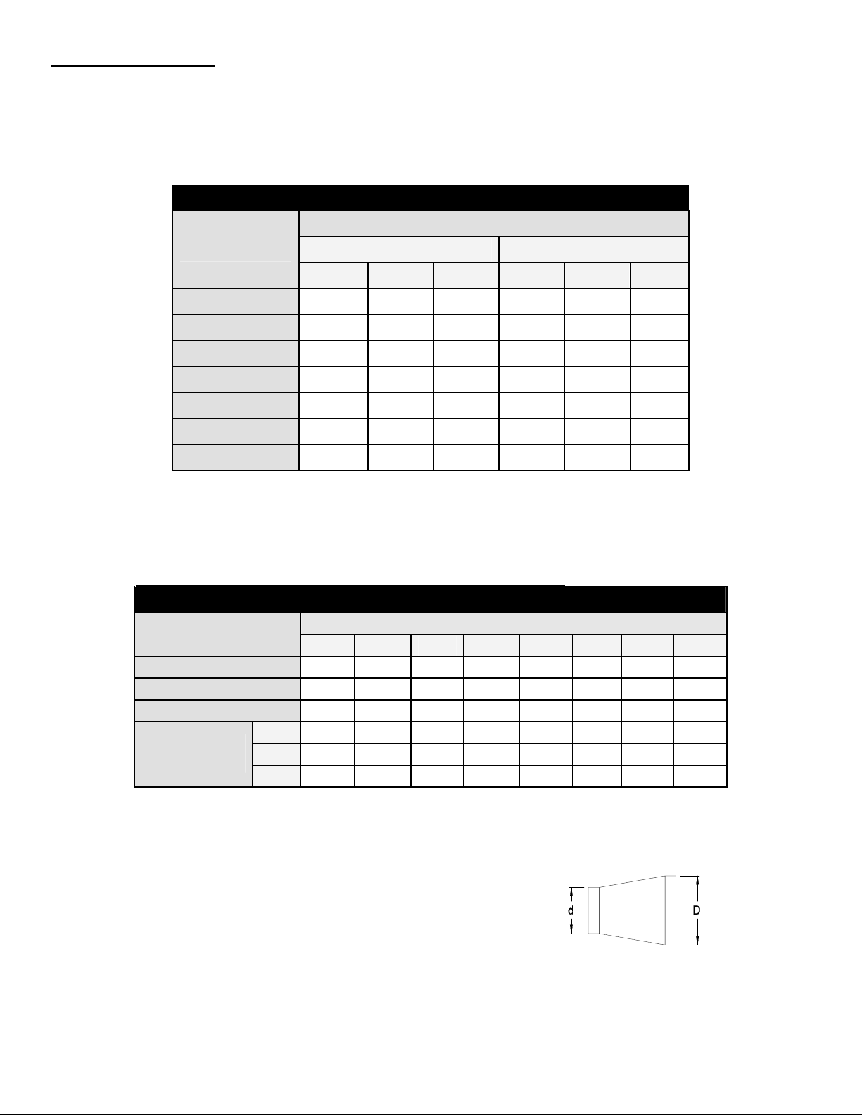
POWER VENTER SIZING
In order to choose the correct size power venter for a particular installation, the total input firing rate and total equivalent
length of vent pipe to be used must be known. Refer to Table 2 to determine the maximum allowable equivalent feet of
pipe for each model used with the pipe diameters shown. When venting multiple appliances, add the input of each
appliance to determine the total input. Always choose a power venter that is capable of handling more than the system
requires. The choke plate can be adjusted to compensate for the difference.
Table 2
MAXIMUM EQUIVALENT HORIZONTAL PIPE LENGTH (FEET)
VENTER MODEL NO. AND VENT PIPE DIAMETER
BTU/HR INPUT
PVO-300 PVO-600
4” 5” 6” 5” 6“ 8”
0.75
1.00
1.50
2.25
3.00
3.75
4.00
287 --- --- --- --- --150 257 346 428 --- ---
75 120 172 212 --- ---
--- 51 70 86 143 211
--- --- --- 46 74 116
--- --- --- --- 51 84
--- --- --- --- --- 77
PROCEDURE FOR CALCULATING TOTAL EQUIVALENT PIPE LENGTH IN FEET
1. Calculate the total equivalent feet for each type of fitting used in the venting system from the following chart.
2. Calculate the total amount of feet for the straight lengths of vent pipe.
3. Add the equivalent feet for the fittings with the total amount of feet of straight lengths.
Table 3
EQUIVALENT LENGTH (FEET) OF VENT PIPE FOR VENT PIPE FITTINGS
VENT PIPE FITTINGS
VENT PIPE DIAMETER
3” 4” 5” 6” 7” 8” 9” 10”
TEE
90° ELBOW
45° ELBOW
19 25 31 38 44 50 56 63
5 7 9 11 12 14 16 18
3 4 4 5 6 7 8 9
1/4 8 11 14 17 19 22 25 28
REDUCER
(d/D)*
1/2 5 7 8 10 12 13 15 17
3/4 2 3 3 4 4 5 6 6
*
Reducer or increaser ratio (d/D) small diameter divided by the larger diameter. (See Figure 3)
Example: 4" to 8" reducer, the reducer ratio is d/D = 4/8 = 1/2. To estimate the equivalent foot
length for the fitting, use the smaller pipe diameter for the equivalent length figure. Example:
4" to 8" reducer; the reducer ratio is 1/2 and the smaller pipe diameter is 4". So, from the chart,
the equivalent feet would be 7 feet.
Example: System Pipe Size = 4"
Step 1 2 – 90° Elbows (4") = 14 Ft.
Step 2 10 - 2 Ft. Lengths of 4" Pipe = 20 Ft.
Step 3 Total Equivalent Feet = 14 Ft. + 20 Ft. = 34 Ft.
Page 3
Figure 3
Diagram A
INSTALLATION SAFETY INSTRUCTIONS
CAUTION: This device must be installed by a qualified installer in accordance with the manufacturer's installation
instructions. Appliances should have a minimum of 75% combustion efficiency or have a maximum measured flue gas
temperature of 550°F at the inlet of the venter.
1. The power venting system must be installed by a qualified installer. "Qualified Installer" shall mean an individual who
has been properly trained or a licensed installer. The installer must write or imprint his name, phone number and date
of installation on the installation tag. The tag should be attached to the power venter unit. Recording burner and
venting system initial operational information is recommended as a guide for service or burner tune-up. Enter this on
the back page of this manual.
2. Safety inspection of a venting system should be performed before and after installing a power venting system on an
existing or new appliance. Procedures to follow are those recommended by the National Fuel Gas Code,
A.N.S.I.Z223.1 or refer to the "General Installation Inspection" section of this manual.
3. Plan the vent system layout before installation to avoid the possibility of accidental contact with concealed wiring or
plumbing inside walls.
4. Single wall vent pipe may be used to join an appliance to the venting system, but if proper clearances cannot be
maintained from combustible materials, Class B Vent Pipe should be used for gas appliances. Refer to national or
local codes for guidelines.
5. Disconnect power supply before making wiring connections to prevent electrical shock and equipment damage.
6. This equipment is designed to overcome minor negative pressure conditions. To ensure extreme negative pressure
does not exist, follow the "General Installation Inspection" section of this manual.
7. Heating appliances equipped with draft hoods, such as boilers or furnaces, LP and natural gas appliances SHOULD
have a secondary spillage switch installed. On appliances without draft hoods, it is recommended that the secondary
safety switch GSK-3 be installed into the system. Gas-fired 30 millivolt power systems MUST be equipped with a
spillage switch.
8. Air flow adjustment MUST be made to ensure appliance efficiency. This should be done at the appliance exhaust
outlet with a velocity meter, draft gauge or by the "match test procedure". The match test is in accordance with
National Fuel Gas Code A.N.S.I.Z223.1, Section 8.6.
9. On heating appliances not equipped with a draft hood, a barometric draft control MUST be installed to regulate proper
air flow and fluctuations in the system's air flow during operation. Fluctuations can come from wind loads on the outlet
of the venter, house depressurization during windy days and the different house ventilation requirements between
summer and winter operation. Use a Field Controls Type MG-1 Barometric Draft Control. Gas-fired draft induced
systems should have a single-acting or double-acting barometric draft control installed.
Page 4
 Loading...