


User Guide
Streaming A/V Products
VN-Matrix™ 200 Series:
VNC 200 DVI, VNE 200 DVI, and VND 200 DVI
DVI and RGB Video Over IP Encoders and Decoders
68-1921-01 Rev. A
02 11

Safety Instructions • English
This symbol is intended to alert the user of important operating and maintenance (servicing) instructions in the literature provided with the equipment.
This symbol is intended to alert the user of the presence of uninsulated dangerous voltage within the product’s enclosure that may present a risk of electric shock.
Caution
Read Instructions • Read and understand all safety and operating instructions before using the equipment. Retain Instructions • The safety instructions should be kept for future reference.
Follow Warnings • Follow all warnings and instructions marked on the equipment or in the user information.
Avoid Attachments • Do not use tools or attachments that are not recommended by the equipment manufacturer because they may be hazardous.
Consignes de Sécurité • Français
Ce symbole sert à avertir l’utilisateur que la documentation fournie avec le matériel contient des instructions importantes concernant l’exploitation et la maintenance (réparation).
Ce symbole sert à avertir l’utilisateur de la présence dans le boîtier de l’appareil de tensions dangereuses non isolées posant des risques d’électrocution.
Attention
Lire les instructions• Prendre connaissance de toutes les consignes de sécurité et d’exploitation avant d’utiliser le matériel.
Conserver les instructions• Ranger les consignes de sécurité afin de pouvoir les consulter à l’avenir.
Respecter les avertissements • Observer tous les avertissements et consignes marqués sur le matériel ou présentés dans la documentation utilisateur.
Eviter les pièces de fixation • Ne pas utiliser de pièces de fixation ni d’outils non recommandés par le fabricant du matériel car cela risquerait de poser certains dangers.
Warning
Power sources • This equipment should be operated only from the power source indicated on the product. This equipment is intended to be used with a main power system with a grounded (neutral) conductor. The third (grounding) pin is a safety feature, do not attempt to bypass or disable it.
Power disconnection • To remove power from the equipment safely, remove all power cords from the rear of the equipment, or the desktop power module (if detachable), or from the power source receptacle (wall plug).
Power cord protection • Power cords should be routed so that they are not likely to be stepped on or pinched by items placed upon or against them.
Servicing • Refer all servicing to qualified service personnel. There are no user-serviceable parts inside. To prevent the risk of shock, do not attempt to service this equipment yourself because opening or removing covers may expose you to dangerous voltage or other hazards.
Slots and openings • If the equipment has slots or holes in the enclosure, these are provided to prevent overheating of sensitive components inside. These openings must never be blocked by other objects.
Lithium battery • There is a danger of explosion if battery is incorrectly replaced. Replace it only with the same or equivalent type recommended by the manufacturer. Dispose of used batteries according to the manufacturer’s instructions.
Avertissement
Alimentations • Ne faire fonctionner ce matériel qu’avec la source d’alimentation indiquée sur l’appareil. Ce matériel doit être utilisé avec une alimentation principale comportant un fil de terre (neutre). Le troisième contact (de mise à la terre) constitue un dispositif de sécurité : n’essayez pas de la contourner ni de la désactiver.
Déconnexion de l’alimentation• Pour mettre le matériel hors tension sans danger, déconnectez tous les cordons d’alimentation de l’arrière de l’appareil ou du module d’alimentation de bureau (s’il est amovible) ou encore de la prise secteur.
Protection du cordon d’alimentation • Acheminer les cordons d’alimentation de manière à ce que personne ne risque de marcher dessus et à ce qu’ils ne soient pas écrasés ou pincés par des objets.
Réparation-maintenance • Faire exécuter toutes les interventions de réparation-maintenance par un technicien qualifié. Aucun des éléments internes ne peut être réparé par l’utilisateur. Afin d’éviter tout danger d’électrocution, l’utilisateur ne doit pas essayer de procéder lui-même à ces opérations car l’ouverture ou le retrait des couvercles risquent de l’exposer à de hautes tensions et autres dangers.
Fentes et orifices • Si le boîtier de l’appareil comporte des fentes ou des orifices, ceux-ci servent à empêcher les composants internes sensibles de surchauffer. Ces ouvertures ne doivent jamais être bloquées par des objets.
Lithium Batterie • Il a danger d’explosion s’ll y a remplacment incorrect de la batterie. Remplacer uniquement avec une batterie du meme type ou d’un ype equivalent recommande par le constructeur. Mettre au reut les batteries usagees conformement aux instructions du fabricant.
Sicherheitsanleitungen • Deutsch
Dieses Symbol soll dem Benutzer in der im Lieferumfang enthaltenen Dokumentation besonders wichtige Hinweise zur Bedienung und Wartung (Instandhaltung) geben.
Dieses Symbol soll den Benutzer darauf aufmerksam machen, daß im Inneren des Gehäuses dieses Produktes gefährliche Spannungen, die nicht isoliert sind und die einen elektrischen Schock verursachen können, herrschen.
Achtung
Lesen der Anleitungen • Bevor Sie das Gerät zum ersten Mal verwenden, sollten Sie alle Sicherheits-und Bedienungsanleitungen genau durchlesen und verstehen.
Aufbewahren der Anleitungen • Die Hinweise zur elektrischen Sicherheit des Produktes sollten Sie aufbewahren, damit Sie im Bedarfsfall darauf zurückgreifen können.
Befolgen der Warnhinweise • Befolgen Sie alle Warnhinweise und Anleitungen auf dem Gerät oder in der Benutzerdokumentation.
Keine Zusatzgeräte • Verwenden Sie keine Werkzeuge oder Zusatzgeräte, die nicht ausdrücklich vom Hersteller empfohlen wurden, da diese eine Gefahrenquelle darstellen können.
Instrucciones de seguridad • Español
Este símbolo se utiliza para advertir al usuario sobre instrucciones importantes de operación y mantenimiento (o cambio de partes) que se desean destacar en el contenido de la documentación suministrada con los equipos.
Este símbolo se utiliza para advertir al usuario sobre la presencia de elementos con voltaje peligroso sin protección aislante, que puedan encontrarse dentro de la caja o alojamiento del producto, y que puedan representar riesgo de electrocución.
Precaucion
Leer las instrucciones • Leer y analizar todas las instrucciones de operación y seguridad, antes de usar el equipo.
Conservar las instrucciones • Conservar las instrucciones de seguridad para futura consulta.
Obedecer las advertencias • Todas las advertencias e instrucciones marcadas en el equipo o en la documentación del usuario, deben ser obedecidas.
•


••
••
Vorsicht
Stromquellen • Dieses Gerät sollte nur über die auf dem Produkt angegebene Stromquelle betrieben werden. Dieses Gerät wurde für eine Verwendung mit einer Hauptstromleitung mit einem geerdeten (neutralen) Leiter konzipiert. Der dritte Kontakt ist für einen Erdanschluß, und stellt eine Sicherheitsfunktion dar. Diese sollte nicht umgangen oder außer Betrieb gesetzt werden.
Stromunterbrechung • Um das Gerät auf sichere Weise vom Netz zu trennen, sollten Sie alle Netzkabel aus der Rückseite des Gerätes, aus der externen Stomversorgung (falls dies möglich ist) oder aus der Wandsteckdose ziehen.
Schutz des Netzkabels • Netzkabel sollten stets so verlegt werden, daß sie nicht im Weg liegen und niemand darauf treten kann oder Objekte daraufoder unmittelbar dagegengestellt werden können.
Wartung • Alle Wartungsmaßnahmen sollten nur von qualifiziertem Servicepersonal durchgeführt werden. Die internen Komponenten des Gerätes sind wartungsfrei. Zur Vermeidung eines elektrischen Schocks
versuchen Sie in keinem Fall, dieses Gerät selbst öffnen, da beim Entfernen der Abdeckungen die Gefahr eines elektrischen Schlags und/oder andere Gefahren bestehen.
Schlitze und Öffnungen • Wenn das Gerät Schlitze oder Löcher im Gehäuse aufweist, dienen diese zur Vermeidung einer Überhitzung der empfindlichen Teile im Inneren. Diese Öffnungen dürfen niemals von anderen Objekten blockiert werden.
Litium-Batterie • Explosionsgefahr, falls die Batterie nicht richtig ersetzt wird. Ersetzen Sie verbrauchte Batterien nur durch den gleichen oder einen vergleichbaren Batterietyp, der auch vom Hersteller empfohlen wird. Entsorgen Sie verbrauchte Batterien bitte gemäß den Herstelleranweisungen.
Evitar el uso de accesorios • No usar herramientas o accesorios que no sean especificamente recomendados por el fabricante, ya que podrian implicar riesgos.
Advertencia
Alimentación eléctrica • Este equipo debe conectarse únicamente a la fuente/tipo de alimentación eléctrica indicada en el mismo. La alimentación eléctrica de este equipo debe provenir de un sistema de distribución general con conductor neutro a tierra. La tercera pata (puesta a tierra) es una medida de seguridad, no puentearia ni eliminaria.
Desconexión de alimentación eléctrica • Para desconectar con seguridad la acometida de alimentación eléctrica al equipo, desenchufar todos los cables de alimentación en el panel trasero del equipo, o desenchufar el módulo de alimentación (si fuera independiente), o desenchufar el cable del receptáculo de la pared.
Protección del cables de alimentación • Los cables de alimentación eléctrica se deben instalar en lugares donde no sean pisados ni apretados por objetos que se puedan apoyar sobre ellos.
Reparaciones/mantenimiento • Solicitar siempre los servicios técnicos de personal calificado. En el interior no hay partes a las que el usuario deba acceder. Para evitar riesgo de electrocución, no intentar personalmente la reparación/mantenimiento de este equipo, ya que al abrir o extraer las tapas puede quedar expuesto a voltajes peligrosos u otros riesgos.
Ranuras y aberturas • Si el equipo posee ranuras o orificios en su caja/alojamiento, es para evitar el sobrecalientamiento de componentes internos sensibles. Estas aberturas nunca se deben obstruir con otros objetos.
Batería de litio • Existe riesgo de explosión si esta batería se coloca en la posición incorrecta. Cambiar esta batería únicamente con el mismo tipo (o su equivalente) recomendado por el fabricante. Desachar las baterías usadas siguiendo las instrucciones del fabricante.
•
•
•
•
•
•

Notational Conventions Used in this Guide
 TIP: A tip provides a suggestion to make setting up or working with the device easier.
 NOTE: A note draws attention to important information.
 CAUTION: A caution warns of things or actions that might damage the equipment.
 WARNING: A warning warns of things or actions that might cause injury, death, or
  other severe consequences.
Copyright
© 2011 Extron Electronics. All rights reserved.
Trademarks
All trademarks mentioned in this guide are the properties of their respective owners.
iii

Contents
IIntroduction........................................................... |
1 |
Overview............................................................. |
1 |
Firmware Version................................................. |
2 |
Product Range..................................................... |
2 |
VNC 200 DVI-I — Codec................................. |
2 |
VNE 200 DVI-I — Encoder Only....................... |
2 |
VND 200 DVI-I — Decoder Only...................... |
3 |
Functional Overview............................................ |
3 |
Encoder Source Compatibility.......................... |
3 |
Decoder Display Capability.............................. |
4 |
Control Capability............................................ |
4 |
Network Requirements.................................... |
4 |
Example System Application............................ |
5 |
Data Transport Methods.................................. |
5 |
Front Panel Features............................................ |
8 |
Indicators........................................................ |
8 |
Reset Button.................................................... |
8 |
Rear Panel Features............................................. |
9 |
Installation and Basic Setup Procedure......... |
10 |
Choosing a Suitable Location for Mounting....... |
10 |
Environmental Requirements............................. |
10 |
Orientation.................................................... |
10 |
Temperature.................................................. |
10 |
Ventilation..................................................... |
11 |
Humidity and Water...................................... |
11 |
Mounting Requirements.................................... |
11 |
Tabletop Mounting ....................................... |
11 |
UL Guidelines for Rack Mounting.................. |
11 |
Rack Mounting.............................................. |
12 |
Under-desk Mounting.................................... |
12 |
Power Connection via PSU................................. |
12 |
Supply Requirements for PSU......................... |
12 |
Power Cord for PSU........................................... |
13 |
Power-up Procedure...................................... |
13 |
Wiring Details................................................ |
13 |
External Supply Protection............................. |
14 |
Setup and Connection Procedure...................... |
14 |
Network Communications Setup................... |
15 |
Connect Devices............................................ |
19 |
System Configuration........................................ |
24 |
VNC 200 Web Interface..................................... |
24 |
Accessing the web interface.......................... |
24 |
Device List Page............................................. |
26 |
Configuring a VNC 200 as an Encoder (Source). 27 |
|
Additional Setup for Audio............................ |
30 |
Additional Information for Encoder Setup...... |
31 |
Configuring a VNC 200 as a Decoder (Display).. |
33 |
Additional Information for Decoder Setup..... |
36 |
Troubleshooting................................................. |
40 |
Display Checkup............................................ |
40 |
Source Checkup............................................ |
42 |
System Checkup............................................ |
43 |
Controller Checkup....................................... |
44 |
Serial Transport and Control Methods........... |
45 |
Overview........................................................... |
45 |
Passthrough Mode......................................... |
45 |
Setting Up a Serial Passthrough Group.............. |
46 |
Serial / Telnet Commands.................................. |
47 |
Control Session Commands........................... |
47 |
Device Commands......................................... |
48 |
Response Messages....................................... |
48 |
Data Stream Mode............................................ |
49 |
Setting Up a Serial Data Stream..................... |
49 |
Remote Keyboard and Mouse Operation...... |
51 |
Overview........................................................... |
51 |
To Initiate a Remote Control Session |
|
Using Hot Keys............................................. |
51 |
To Terminate a Remote Control Session |
|
Using Hot Keys............................................. |
52 |
Mouse and Keyboard Control........................ |
52 |
Encoder Set Up.................................................. |
55 |
Advanced Source Setup..................................... |
55 |
Video Setup Page.......................................... |
56 |
Fine-tuning a Source (Manual Overrides)........ |
57 |
Custom Input Modes..................................... |
58 |
Managing Compression and Bandwidth |
|
Settings............................................................ |
64 |
Bandwidth (Source) Page............................... |
64 |
Bandwidth Management .............................. |
66 |
Bandwidth Management – Simple Control..... |
67 |
Extron VN-Matrix 200 Series • Contents |
iv |

Bandwidth Management – Advanced |
|
Control......................................................... |
68 |
Bandwidth Management Settings ................. |
70 |
Audio Compression....................................... |
71 |
Decoder Set Up................................................. |
72 |
Setting Optimum Playback Delay................... |
72 |
Custom Output Modes.................................. |
75 |
Controller Configuration................................... |
79 |
Changing User Login Passwords.................... |
79 |
Controller Licensing....................................... |
80 |
Upgrading Device Firmware........................... |
80 |
Changing a Device Licence............................ |
83 |
Alarms and SNMP................................................ |
85 |
Overview – Alarms............................................. |
85 |
Alarms Page...................................................... |
86 |
Filter Settings................................................. |
86 |
Alarm Type.................................................... |
87 |
Alarm Source................................................. |
87 |
Alarm Severity............................................... |
87 |
Alarm Reporting............................................ |
87 |
Applying Alarm Filter Settings........................ |
87 |
Alarm List...................................................... |
87 |
Alarm Logs.................................................... |
88 |
Alarm Type Description - Encoder ................. |
89 |
Alarm Type Description - Decoder.................. |
90 |
Alarm Type description - Controller................ |
90 |
Overview – SNMP.............................................. |
91 |
Using SNMP - Password................................. |
91 |
SNMP Trap Version........................................ |
91 |
SNMP Community......................................... |
91 |
SNMP Trap Destinations..................................... |
92 |
IP Addressing........................................................ |
93 |
What is an IP Address?...................................... |
93 |
Private and Public Address Ranges................. |
93 |
Multicast Address Range................................ |
94 |
Choosing IP Addresses....................................... |
94 |
Subnet Mask................................................. |
95 |
Using the Ping Utility to Test Communications... |
95 |
Response Messages....................................... |
95 |
Understanding Network Performance........... |
97 |
Network Characteristics..................................... |
97 |
Data Packets/Frames...................................... |
97 |
Nodes, Switchers, and Routers....................... |
98 |
Browser Configuration..................................... |
101 |
Internet Explorer (v6 or Above)........................ |
101 |
Mozilla (v1.3 or Above).................................... |
103 |
Technical Data.................................................... |
105 |
VNC 200 Hardware......................................... |
105 |
Connectors.................................................. |
105 |
RS-232 Port Settings.................................... |
111 |
Serial Port Login Procedure.......................... |
112 |
Command options....................................... |
112 |
Telnet Interface – Quick Reference................... |
113 |
Starting Telnet............................................. |
113 |
Login Procedure........................................... |
113 |
Reference Information..................................... |
114 |
Specifications.................................................. |
114 |
Accessories...................................................... |
117 |
Supplied Accessories.................................... |
117 |
Optional Accessories.................................... |
117 |
Extron VN-Matrix 200 Series • Contents |
v |

Introduction
This section introduces you to the VN-Matrix 200 Series (VN 200). The topics covered in this section are:
•Overview
•Firmware Version
•Product Range
•VNC 200 DVI-I — Codec
•VNE 200 DVI-I — Encoder Only
•VND 200 DVI-I — Decoder Only
•Functional Overview
•Front Panel Features
•Rear Panel Features
 NOTE: This document covers the VNC 200 DVI-I (Codec) matrix switcher only,
although both the VNE 200 and VND 200 may be referenced. Encoder
features may apply to the VNE 200. Decoder features may apply to the
VND 200.
Overview
The VN-Matrix 200 devices distribute RGB video and graphics from a source computer or similar graphical device across an IP network to one or more viewing stations.
An RGB signal is captured or acquired by a VNC 200 or VNE 200 unit and encoded into a TCP or RTP data stream for transport across a local area or wide area network. Elsewhere on the network another VNC 200 or a VND 200 unit can decode the stream back into an analog RGB or digital (DVI) signal suitable for display on a wide range of display devices.
In addition to an RGB signal, the VNC 200 can provide cross-network transport of:
•Digital audio (SPDIF)
•Serial data (RS-232).
 NOTE: Digital audio may accompany video, graphics, or both sources. The VN 200
  cannot transport an “audio only” signal.
RS-232 serial data can be distributed between VNC 200 units unidirectionally as part of the source stream (data channel) or bidirectionally independent of any source streams (passthrough).
VN-Matrix 200 Series • Introduction |
1 |

Firmware Version
This user guide is based on v3.8 firmware. You can check for newer firmware releases and user guide updates by visiting our web site at www.extron.com/downloads.
TIP: |
To check which version of firmware is currently installed, see “Upgrading |
|
Device Firmware.” |
Product Range
There are three VN 200 Matrix products. These units are compatible with each other, but there are some feature limitations and differences between each variant.
VNC 200 DVI-I — Codec
This unit:
•May be configured as either an encoder or a decoder
•Supports the full use of remote keyboard and mouse
•Remote and RS-232 ports are enabled
|
|
IN |
TO PC |
REMOTE |
|
RS-232 |
POWER |
|
IN |
|
|
|
|
|
|
|
|
|
OVER LAN |
|
|
|
OUT/ |
|
|
|
|
|
|
LOOP |
|
|
|
|
12V DC |
AUDIO |
1 — LAN — 2 |
|
OUT/LOOP |
DVI-I |
IN |
5A MAX |
SPDIF |
|
||||
|
|
|
|
|
CODEC
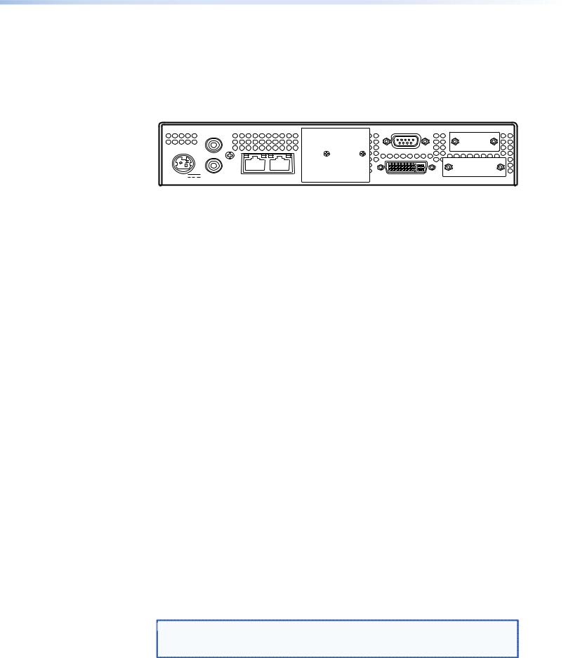
Figure 1. VNC 200 DVI-I, CODEC — Back Panel
VNE 200 DVI-I — Encoder Only
The VNE 200 is an encoder-only device and is compatible with the other products in the VN-Matrix family.
NOTE: The VNE 200 does not support: |
|
|
|
|||
• |
Mouse and keyboard operation |
|
|
|
||
• |
RS-232 client / server operation |
|
|
|
||
|
|
|
REMOTE |
|
RS-232 |
|
POWER |
|
IN |
|
|
|
|
|
|
|
|
|
||
|
|
OUT/ |
|
|
|
|
|
|
LOOP |
|
|
|
|
12V DC |
AUDIO |
1 — LAN — 2 |
OUT/LOOP |
DVI-I |
IN |
|
5A MAX |
SPDIF |
|||||
|
|
|
|
|||
Encoder
Figure 2. VNE 200 DVI-I, Encoder — Back Panel
VN-Matrix 200 Series • Introduction |
2 |
VND 200 DVI-I — Decoder Only
The VND 200 is a decoder-only device and is compatible with other VN-Matrix products including the VNM Enterprise Controller and the VNC 200 configured as a controller.
The VND 200 does not support:
•Mouse and keyboard operation
•RS-232 client / server operation
|
|
|
REMOTE |
RS-232 |
|
|
|
IN |
|
|
|
POWER |
|
|
|
|
|
|
|
OUT/ |
|
|
|
|
|
LOOP |
|
|
|
12V DC |
AUDIO |
1 — LAN — 2 |
OUT/LOOP |
DVI |
|
5A MAX |
SPDIF |
||||
|
|
|
|||
Decoder |
|
|
|
|
Figure 3. VND 200 DVI-I, Decoder — Back Panel
Functional Overview
Device Name |
Part Number |
Standard Features |
Optional Features |
|
|
|
|
|
by License |
VNC 200 |
DVI-I |
60-1117-01 |
Codec, video, keyboard |
Whiteboard and data |
|
|
|
and mouse, output scaling, |
support |
|
|
|
RS-232 |
|
VNC 200 |
DVI-A |
60-1118-01 |
Codec, video, audio, |
Whiteboard and data |
|
|
|
keyboard and mouse, |
support |
|
|
|
output scaling, RS-232 |
|
VNE 200 DVI-I |
60-1119-01 |
Encoder, video, audio |
None |
|
VND 200 |
DVI-I |
60-1120-01 |
Decoder, video, audio, |
None |
|
|
|
output scaling |
|
The VNC 200 can be configured to operate in one of two modes:
•As an encoder to encode a source and stream it across a network
•As a decoder to decode and display a VNC 200 data stream from a network
Any VNC 200 matrix system will contain at least two devices, one configured as an encoder and the other as a decoder. Multiple encoders and decoders may co-exist on the same network.
Encoder Source Compatibility
As an encoder, the VNC 200 is compatible with digital (DVI) and analog (RGB) graphic sources up to WUXGA (1920 x 1200) resolution (see “Technical Data” for a list of standard supported sources).
The VNC 200 incorporates advanced image acquisition circuitry which can auto-detect a wide range of source types without the need for any additional setup.
For special or non-standard source formats, user-customizable source modes can be created using the web interface (see “Advanced Source Setup” for further details).
 NOTE: The VNC 200 provides analog-to-digital or digital-to-analog conversion via its
monitor connections. Therefore, it is possible to use a digital monitor with an analog source and vice versa.
VN-Matrix 200 Series • Introduction |
3 |

Decoder Display Capability
As a decoder, the VNC 200 is compatible with both digital (DVI) and analog (RGB) graphics sources up to UXGA (1600 x 1200 at 60 Hz, 24-bit color) resolution.
 NOTE: By default, sources are displayed at their native resolution and format.
The decoded image may also be scaled by the decoder to match the native resolution of the local display.
Control Capability
Source control
The VNC 200 provides loop-through connections for the keyboard and mouse of the source computer. Local keyboard and mouse control of the source computer is fully maintained while connected to the VNC 200. In addition, keyboard and mouse functions can be remotely controlled from the viewing station.
System setup and configuration
Low level communications setup of the VNC 200 is achieved using a serial data link connected to the Remote port. High level configuration is achieved via the network using the Integrated Web Management System.
Integrated web management system
The VNC 200 incorporates an integrated web management system (web interface). This allows any VNC 200 unit on a network to be configured via a PC/laptop (on the same network), using a standard web browser (for example, Internet Explorer or FireFox).
One VNC 200 unit on the network must be designated as a controller. This unit acts as a server for the web interface and also holds a database of all VNC 200 devices on the network.
Any VNC 200 unit, whether it is configured as an encoder or decoder, can be used as a controller.
The web interface includes a full online help system.
Remote Control
RS-232 serial data can be routed between selected VNC 200 units, for example, to provide remote control of a source.
Network Requirements
VNC 200 uses highly efficient compression algorithms to minimize the amount of required data transported across the network.
It is, however, crucial to the effective operation of the VNC 200 that sufficient data throughput can be achieved, especially where multiple sources are being encoded.
The efficiency of a network will be directly affected by the speed and configuration of each element within its infrastructure, that is, switchers and routers. The VNC 200 will achieve optimum transmission results over a dedicated 1 Gbps network (gigabit Ethernet). For more general information on networks and network performance, see
“Understanding Network Performance”.
VN-Matrix 200 Series • Introduction |
4 |
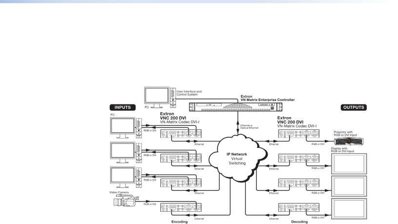
Example System Application
The diagram below shows an example system application utilizing eight VNC 200 units. Four are configured as encoders (sources) and four as decoders (displays). Each device is connected to the network.
Configuration of each device, including which source is displayed on which display, can be achieved by any PC or laptop on the same network using the VNC 200 integrated web management system.
Figure 4. Using the VN 200 Matrix to Integrate a Web Management System
In this example, each of the four sources is shown separately on the four displays. Potentially however, any display can broadcast any source.
Data Transport Methods
Source data from a VNC 200 or a VNE 200 encoder can be distributed to multiple displays/ decoders (one-to-many) or to a single display/decoder (point-to-point).
Video data is transported from the source (encoder) to the display (decoder) using one of three methods:
•Multicast RTP
•Unicast RTP
•Unicast TCP
A description of each method, together with its advantages and disadvantages, can be found on the next few pages.
VN-Matrix 200 Series • Introduction |
5 |
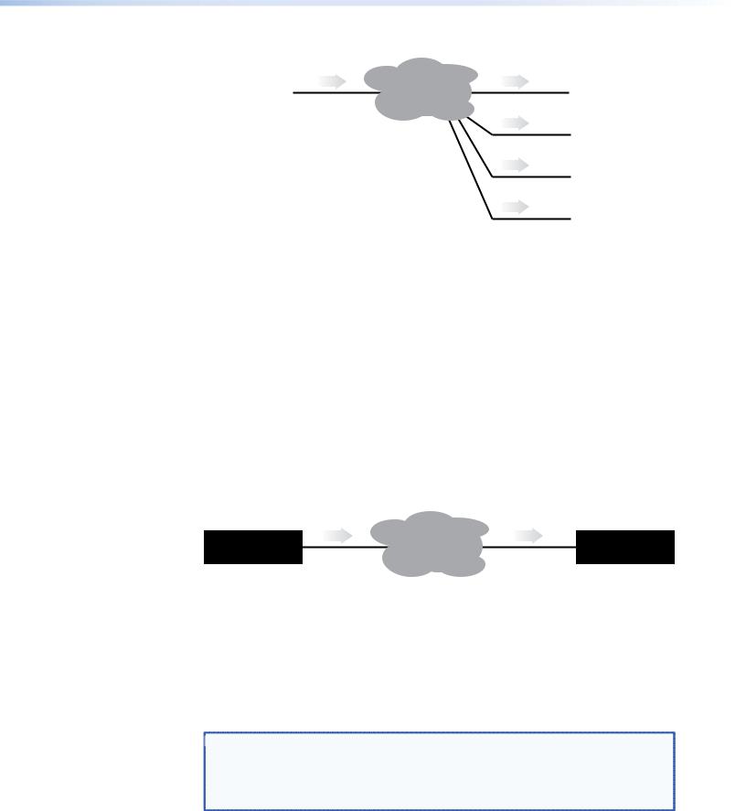
Multicast RTP
This method uses a real-time variation of UDP (User Datagram Protocol), called RTP (Realtime Transport Protocol). Multicast RTP allows a source to be displayed on any number of displays.
SOURCE |
|
|
|
|
|
DISPLAY |
|||
|
|
|
RTP |
|
RTP |
|
|
|
|
VN-MATRIX |
|
|
NETWORK |
|
|
VN-MATRIX |
|
||
|
|
|
|
|
|
|
|||
(encoder) |
|
|
|
|
|
|
(decoder) |
|
|
|
|
|
|
|
RTP |
|
|
|
|
Encoder sends data using RTP |
|
|
|
VN-MATRIX |
|
||||
|
|
|
|
|
|||||
|
|
|
|
(decoder) |
|
||||
to a multicast group |
|
|
|
|
|
|
|||
|
|
|
|
|
RTP |
|
|
|
|
|
|
|
|
|
|
|
VN-MATRIX |
|
|
|
|
|
|
|
|
|
|
|
|
|
|
|
|
|
|
|
|
(decoder) |
|
|
|
|
|
|
RTP |
|
|
|
|
|
|
|
|
|
|
|
VN-MATRIX |
|
|
|
|
|
|
|
|
|
|
|
|
|
|
|
|
|
|
|
|
(decoder) |
|
|
|
|
|
|
RTP |
|
|
|
|
|
|
|
|
|
|
|
|
|
|
|
|
|
|
|
|
|
|
||
|
|
|
|
|
Any number of decoders can be |
||||
|
|
|
|
|
|
part of the multicast group |
|||
Figure 5. Multicast RTP |
|
|
|
|
|
|
|||
The source encoder uses RTP to send data to a multicast group. The source encoder does not need to know the IP address of any decoders that use that source.
RTP provides very low latency which is important for video transport. Unlike other protocols, RTP packets include a timestamp. Therefore, if packets are received in the wrong order they can easily be sorted into the correct order for display, or discarded if the timestamp is out-of-date.
However, because RTP is a connectionless protocol, data delivery is not guaranteed. Where data packets are lost (for example, due to excessive network traffic) the VNC 200 carefully manages the data stream to minimize any image disruption.
Unicast RTP
Like multicast RTP, this method uses a real-time variation of UDP protocol, called RTP. This method can be used where the network infrastructure does not support multicast traffic. Unicast RTP should be used as a point-to-point configuration (that is, single source to single display) but can be used for up to four displays.
VN-Matrix 200 Series • Introduction |
6 |
SOURCE |
|
|
|
|
DISPLAY |
|||
|
|
|
RTP |
|
RTP |
|
|
|
VN-MATRIX |
|
|
NETWORK |
|
VN-MATRIX |
|
||
|
|
|
|
|
|
|||
(encoder) |
|
|
|
|
|
(decoder) |
|
|
|
|
|
|
|
RTP |
|
|
|
Encoder sends data using RTP |
|
|
VN-MATRIX |
|
||||
|
|
|
|
|||||
|
|
|
(decoder) |
|
||||
to up to 4 specified decoders |
|
|
|
|
||||
|
|
|
|
|
RTP |
|
|
|
|
|
|
|
|
|
VN-MATRIX |
|
|
|
|
|
|
|
|
|
|
|
|
|
|
|
|
|
|
(decoder) |
|
|
|
|
|
|
RTP |
|
|
|
|
|
|
|
|
|
VN-MATRIX |
|
|
|
|
|
|
|
|
|
|
|
|
|
|
|
|
|
|
(decoder) |
|
Figure 6. Unicast RTP
The source encoder defines the display decoder(s) that the source is available to, but the decoder chooses which source to display.
RTP provides very low latency which is important for video transmission. Unlike other protocols, RTP packets include a time stamp. Therefore, if packets are received in the wrong order they can easily be sorted into the correct order for display, or discarded if the timestamp is out-of-date.
However, because RTP is a connectionless protocol, data delivery is not guaranteed. Where data packets are lost (for example, due to excessive network traffic) the VNC 200 carefully manages the data stream to minimize any image disruption.
Unicast TCP
This method transmits data using standard TCP (Transmission Control Protocol) and should only be used for single point-to-point transfer of data.
SOURCE
VN-MATRIX TCP (encoder)
NETWORK
DISPLAY
TCP VN-MATRIX (decoder)
Decoder makes a TCP connection with the specified encoder
Figure 7. Unicast TCP
TCP is a connection-based protocol and, therefore, data is guaranteed to be delivered. However, in the event of excessive network traffic, delivery may be delayed and will impact real-time performance.
The decoder defines which source to connect to. Other than defining an IP Address and source type (if required) no special source encoder setup is required.
 NOTE: Multiple decoder connections are theoretically possible using this method but
NOT recommended. Each additional connection will create extra loading on
the encoder CPU which will ultimately result in poor display performance. In
addition, multiple TCP streams carrying the same source data is an inefficient use of network bandwidth.
VN-Matrix 200 Series • Introduction |
7 |
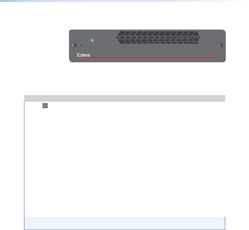
Front Panel Features
 LAN-1
LAN-1
 LAN-2
LAN-2
 STATUS
VN-MATRIX 200 SERIES
RGB/DVI OVER IP
Figure 8. VN-Matrix 200 Front Panel
Indicators
The following indicators are visible on the front of the VNC 200:
Name |
Color |
Function |
|
|
|
POWER - |
Green |
• Fully Lit – When the unit is receiving power from the 12V supply input. |
|||
|
|
|
|
|
|
|
|
• Flashing – An over temperature condition has occurred or there was a power |
|||
|
|
|
overload or underload condition. Cycle the power off and then on to reset. |
||
LAN - 1 |
Orange |
Indicates the status of network port 1: |
|
||
|
|
• Fully Lit or Flashing Intermittently – Control or source data is being |
|||
|
|
|
transmitted or received by the port. |
|
|
|
|
• Unlit – No data or no network connection detected. |
|
||
LAN - 2 |
Orange |
Indicates the status of network port 2: |
|
||
|
|
• Fully Lit or Flashing Intermittently – Control or source data is being |
|||
|
|
|
transmitted or received by the port. |
|
|
|
|
• Unlit – No data or no network connection detected. |
|
||
STATUS |
Green |
Indicates the source status of the VNC 200: |
|
||
|
|
|
|
|
|
|
|
|
Condition |
Encoder (source) |
Decoder (display) |
|
|
|
Unlit |
No source input detected |
No source being |
|
|
|
|
|
received |
|
|
|
Flashing |
Source being streamed |
Source being received |
|
|
|
Fully Lit |
Source present but not being streamed |
N/A |
|
|
|
|
(that is, unit currently disabled or in |
|
|
|
|
|
standby mode) |
|
|
|
|
|
|
|
NOTE: During the VNC 200 boot up period (typically 20-30 seconds) the NETWORK and STATUS indicators may light up or flash intermittently while the unit initializes.
Reset Button
The VNC 200 is fitted with a concealed reset button on the front panel. This can be used to reboot the operating system, for example, during firmware upgrade procedures.
To activate this button, insert the blade of a very small screwdriver (or similar tool) or straightened paper clip into the hole on the front panel to the left of the LED indicators.
VN-Matrix 200 Series • Introduction |
8 |
Rear Panel Features
|
|
e |
g |
j |
k |
|
|
IN |
TO PC |
REMOTE |
RS-232 |
POWER |
|
IN |
|
|
|
|
|
|
|
OVER LAN |
|
|
|
OUT/ |
|
|
|
|
|
LOOP |
|
|
|
12V DC |
AUDIO |
1 — LAN — 2 |
|
OUT/LOOP |
DVI-I IN |
5A MAX |
SPDIF |
|
|||
|
|
|
|
||
a |
b |
c d |
f |
h |
i |
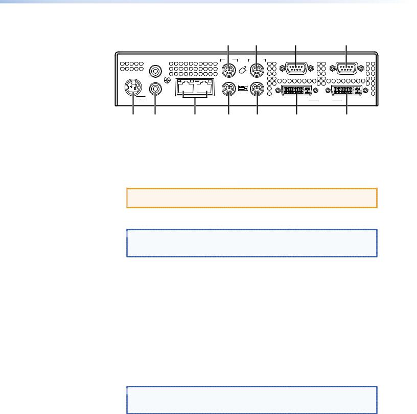
Figure 9. VN-Matrix 200 Rear Panel
Full details of connector types, pin-outs, and specifications can be found in the “Technical Data” section. Briefly, these are as follows:
ADC power connector — The VNC 200 requires a 12 VDC regulated power supply via this connector. A suitable power supply unit (PSU) is provided.
 CAUTION: Unless otherwise stated, the power supply unit is not suitable for use in air handling spaces or in wall cavities.
BAudio SPDIF connectors — Two female RCA connectors for input or output/ loop-through of digital audio signals through S/PDIF coaxial cables.
 NOTE: Loop-through means that the input is output unprocessed. This feature
only applies to an encoder or a codec configured as an encoder. It does not apply to a decoder.
CLAN network connectors (1 and 2) — Two female RJ-45 connectors are used to connect the VN 200 to an Ethernet network. Typically, port 1 is used for data streaming and device configuration (using the web interface). Port 2 is reserved for future use and special applications.
DKeyboard connector — Connect the keyboard to the PS/2 port.
EMouse connector — Connect the mouse to the PS/2 port.
FPC keyboard connector — Connect the VN 200 PS/2 keyboard port to the PS/2 keyboard port of the PC.
GPC mouse connector — Connect the VN 200 PS/2 mouse port to the PS/2 mouse port of the PC.
HDVI-I out/loop connector — Connect the computer monitor to the female DVI-I output/loop-through port.
 NOTE: Loop-through means that the input is output unprocessed. This feature
only applies to an encoder or a codec configured as an encoder. It does not apply to a decoder.
IDVI-I input connector — Connect the DVI-I output port of the computer to the female DVI-I input port.
JRemote serial connector — This male 9-pin communications port is typically used to configure the VN 200.
KRS-232 serial connector (over LAN) — This male 9-pin port is typically used to transmit and receive data across a network.
VN-Matrix 200 Series • Introduction |
9 |

Installation
and Basic Setup
Procedure
This section describes the following:
•Choosing a Suitable Location for Mounting
•Environmental Requirements
•Mounting Requirements
•Power Connection via PSU
•Power Cord for PSU
•Setup and Connection Procedure
Choosing a Suitable Location for Mounting
The VNC 200 is designed to be used either as a free-standing unit or mounted in a 19-inch rack using optional mounting kits.
CAUTION: Whichever installation method you choose there are certain environmental requirements, detailed in “Environmental Requirements”, which must be observed in order to ensure safe and reliable operation.
For rack-mounted applications the criteria detailed in “Mounting
Requirements” must also be observed.
Environmental Requirements
 CAUTION: The criteria in this section must be observed for all installations of the VNC 200, whether free-standing or rack-mounted.
Orientation
The VNC 200 is designed to be used free-standing on a stable, horizontal surface. It can, however, be used in any orientation subject to the necessary ventilation requirements.
Temperature
DO NOT install or operate the VNC 200 in an area where the ambient temperature exceeds 35°C (95°F) or falls below 5°C (35°F).
As with all electronic equipment, the VNC 200 and its associated PSU produce heat which may affect the ambient temperature.
VN-Matrix 200 Series • Installation |
10 |

After the VNC 200 has been in use for a period of time the external casing may become slightly warm to the touch. Ensure that any adjacent surfaces will not be affected by the heat.
Ventilation
DO NOT obstruct the ventilation openings during use. The VNC 200 has an integral forced-air cooling system. A fan draws air in through the ventilation openings in the front panel and expels the heated air through the openings in the back panel. The fan speed is controlled automatically by an internal temperature sensor. The fan may, therefore, appear to run faster as the unit warms up or if the ambient temperature is increased.
A self-resetting thermal cutout will shutdown the VNC 200 if the temperature exceeds design limits.
Humidity and Water
DO NOT install or operate the VNC 200 in an area:
•In which the ambient relative humidity exceeds 85%
•That is prone to condensation
•Near water or in a location which may be prone to water seepage
Mounting Requirements
Tabletop Mounting
If not already attached, attach the four rubber feet to the bottom of the unit and place it in a suitable location.
CAUTION: For rack-mounted installations, the following criteria must be observed (in addition to the environmental requirements listed in “Environmental Requirements.”
UL Guidelines for Rack Mounting
The following Underwriters Laboratories (UL) guidelines are relevant to the safe installation of these products in a rack:
1.Elevated operating ambient temperature — If the unit is installed in a closed or multi-unit rack assembly, the operating ambient temperature of the rack environment may be greater than room ambient temperature. Therefore, install the equipment in an environment compatible with the maximum ambient temperature (Tma: +95 °F, +35 °C) specified by Extron.
2.Reduced air flow — Install the equipment in the rack so that the equipment gets adequate air flow for safe operation.
3.Mechanical loading — Mount the equipment in the rack so that uneven mechanical loading does not create a hazardous condition.
4.Circuit overloading — Connect the equipment to the supply circuit and consider the effect that circuit overloading might have on overcurrent protection and supply wiring. Appropriate consideration of the equipment nameplate ratings should be used when addressing this concern.
5.Reliable earthing (grounding) — Maintain reliable grounding of rack-mounted equipment. Pay particular attention to supply connections other than direct connections to the branch circuit (such as the use of power strips).
VN-Matrix 200 Series • Installation |
11 |

Rack Mounting
Always use the special under-desk mounting kits (optional) to secure the VNC 200. See “Optional Accessories” for the under-desk mounting kit. Full details on using the kit are included with each kit. It will be necessary to remove the four feet prior to rack mounting.
Never place other units directly on top of the VNC 200 when it is rack-mounted as this will place excessive strain on the mounting brackets.
Under-desk Mounting
Always use the special under-desk mounting kit (optional) to secure the VNC 200. See “Optional Accessories” for the under-desk mounting kit. Full details on using the kit are
included with each kit.
Power Connection via PSU
Always ensure that the power supply is the correct voltage and frequency for all equipment within the rack, and that it has a good ground (earth) connection.
Where a power strip is used, always ensure that the current rating of both the power strip and the supply is sufficient for all equipment within the rack.
The VNC 200 must be powered from a 12 VDC regulated supply. A suitable power supply unit (PSU) is provided. The power connection details that follow relate to the PSU.
CAUTION:
•Never connect the VNC 200 directly to the power source.
•To ensure CE compliance always use the PSU provided.
•If a backup or replacement PSU is required, always use an Extron approved PSU.
Supply Requirements for PSU
 CAUTION: Always observe the following instructions to ensure safe and reliable operation of the PSU.
Always ensure that the supply voltage is single phase only and is within the permitted range:
100 – 240 VAC (0.45 A Max.) 50 – 60 Hz. NEVER connect the PSU to a DC supply.
DO NOT allow the power outlet to be overloaded. This is particularly important to check when powering several items of equipment from a single power outlet (that is, within rack-mounted installations).
WARNING: |
• This equipment must be grounded. |
• To avoid the possible risk of electric shock or product damage due to con- |
densation, ALWAYS allow the PSU to adapt to the ambient temperature and |
humidity for at least thirty minutes BEFORE switching on. This is particularly |
important when moving the unit from a cold location to a warm location. |
VN-Matrix 200 Series • Installation |
12 |

Power Cord for PSU
The PSU is equipped with a 3-pin (male) type connector which requires a power cord fitted with a corresponding 3-pin IEC320 (female) connector.
The type of power cord that is supplied will be appropriate for use in your country:
 WARNING: Do not allow anything to rest on the power cord.
Power-up Procedure
You must always ensure that the VNC 200 is powered on at the same time as the source computer or slightly before.
Powering the VNC 200 after the source computer may result in the source computer not correctly detecting the mouse, keyboard, monitor, or all three.
Attaching a Power Plug
If you are attaching a plug to an unterminated power cord (or replacing an existing plug), you must fit a plug that is:
•Rated for use with mains voltage
•Equipped with a grounding pin or connection
•In compliance with any applicable national or local electrical regulations
•Fitted with a correctly rated fuse (applicable to UK-style plugs only (see “Setup and Connection Procedure.”)
 WARNING: Never attempt to fit or use a plug without a ground connection.
Wiring Details
The wires of both power cords (supplied with each VNC 200) are color-coded as shown in the table below. Be sure to connect your plug in accordance with the following guidelines:
Connect the wire colored... |
to the plug terminal identified with... |
|
|
Brown |
‘L’ or ‘Live’ or ‘Line’ |
|
(or colored red or brown) |
Blue |
‘N’ or ‘Neutral’ |
|
(or colored blue or black) |
Green and Yellow |
‘E ’ or ‘E’ or ‘Earth’ or ‘Ground’ |
|
(or colored green or green-and-yellow) |
 WARNING: If you are unsure of the connections, or if the markings in your plug do
  not match those given above, consult a qualified electrician.
 NOTE: The PSU is double insulated and does not require an ground connection.
However, the ground cable of the lead must be connected in the plug.
VN-Matrix 200 Series • Installation |
13 |

External Supply Protection
 CAUTION: The power cord supplied with this product is rated at 10A maximum and must be protected from overload by an external fuse or circuit breaker.
Fused plugs (UK style)
If the power cord is fitted with a UK style BS1363 3-pin plug (i.e. with provision for an internal fuse), then it must be fitted with a BS1362 ASTA approved 1 inch cartridge fuse.
This fuse must be rated at a maximum of 10A/250V. Since the current draw of the PSU is less than 1A, a fuse of a lower rating not less that 3A/250V may be used.
 WARNING: Never attempt to fit a fuse or circuit breaker of a higher maximum
  rating than shown above.
Unfused plugs or hard-wired
If the power cord is fitted with an unfused plug or it is hard-wired into a power strip, then the power cord must be protected by an external fuse or circuit breaker of a rating shown in the table below:
Supply Voltage |
110V nominal |
230V nominal |
|
|
|
Maximum Fuse Rating |
10A |
10A |
|
|
|
Minimum Fuse Rating |
3A |
3A |
|
|
|
 WARNING: Never attempt to fit a fuse or circuit breaker of a
  higher maximum rating than shown above.
Setup and Connection Procedure
Setting up and connecting an VNC 200 system is best undertaken in three steps.
•Step 1. Network Communications Setup
Configure the network settings for each device using a PC or laptop and serial data link, ensuring that one device is configured as a controller (see“Network
Communications Setup”).
•Step 2. Connect Devices
Connect each device to the network and connect its associated source or display equipment (see “Connect Devices”).
Step 3. System Configuration
Use a PC or laptop connected to the VN-Matrix network to access the web interface (served by the controller) to configure each device to be an encoder (source) or decoder (display) (see “System Configuration”).
CAUTION: Do not proceed with connecting or configuring the VNC 200 for an existing network until you are certain you know what you are doing. Incorrect connection or configuration may cause disruption to other network users.
VN-Matrix 200 Series • Installation |
14 |
Network Communications Setup
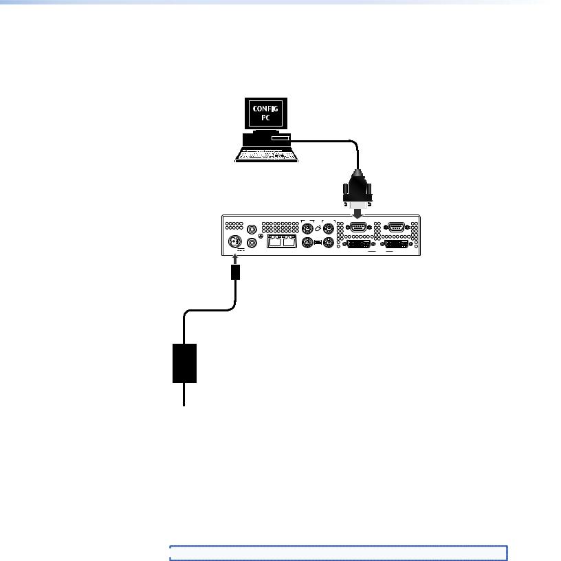
To establish a serial communication link…
1.Using a null modem serial cable, connect the serial port of a PC or laptop to the Remote serial port on the VNC 200 to be configured.
VNC 200 |
IN TO PC |
RS-232 |
|
|
IN |
|
|
|
|
POWER |
|
|
|
|
OVER LAN |
|
|
|
OUT/ |
|
|
|
|
|
|
LOOP |
|
|
|
|
12V DC |
AUDIO |
1 — LAN — 2 |
OUT/LOOP |
DVI-I |
IN |
|
5A MAX |
SPDIF |
|||||
|
|
|
|
PSU
Power
Source
Figure 10. Establishing a Serial Communication Link
2.On the PC or laptop, run a terminal emulation program such as HyperTerminal with the following comm settings:
Baud rate: |
115200 |
Data bits: |
8 |
Parity: |
None |
Stop bits: |
1 |
Flow control: |
None |
 NOTE: HyperTerminal is supplied with most Windows® operating systems.
VN-Matrix 200 Series • Installation |
15 |
To access the setup menus…
1.Connect power to the VNC 200 or, if already connected, cycle the power off then on.
2.The VNC 200 will start sending setup/diagnostic data which should appear in the HyperTerminal window. After a few seconds, this will conclude with a display similar to this:
VN Matrix(R) Maintenance Console: ver3.1c
(none) login: ThorPci Init
registering plx interrupt routine = D17F89FC, -780166896 Hello kernel
thor_init_module: pre-ioremap thor_init_module: post-ioremap Hello kernel, this is MK registering
registering plx interrupt routine = D296BD30, 0
3.Press the <Enter> key. The VNC 200 should respond with the following login prompt:
VN Matrix™ Maintenance Console: ver3.1c 192.168.0.1 login:
 NOTE: The login prompt will be preceded by the current IP address of the unit.
4.Type: config <Enter>
5.When prompted for a password type config followed by the <Enter> key. The following menu of options will then appear:
|
Network Port 1 |
|
Network Port 2 |
||
0. |
Speed/Duplex: auto_10_100_1000 |
10. |
Speed/Duplex: auto_10_100_1000 |
||
1. |
Boot method: |
static [dhcp] |
11. |
Boot method: |
static [dhcp] |
2. |
Address: |
192.168.0.1 |
12. |
Address: |
192.168.1.1 |
3. |
Netmask: |
255.255.255.0 |
13. |
Netmask: |
255.255.255.0 |
4. |
Gateway: |
192.168.0.1 |
14. |
Gateway: |
192.168.0.1 |
5. |
Broadcast: |
|
15. |
Broadcast: |
|
6. |
MTU: |
1500 |
16. |
MTU: |
1500 |
7. |
Controller IP: |
192.168.0.18 |
17. |
IP forwarding: |
0 |
8. |
Controller port: |
5432 |
18. |
Webserver port: |
80 |
9. |
Exit |
|
|
|
|
|
|
NOTE: The IP address details shown above are for illustration only and do not |
|||
|
|
|
represent values that will work in a particular application. |
||
The following table describes the menu options in greater detail.
6.Change the settings as required by typing the option number followed by the <Enter> key. Then type the new value followed by the <Enter> key.
For example, to change the Network Port 1 IP address to 172.28.232.16: Type: 2 <Enter>, then type: 172.28.232.16 <Enter>
 NOTE: Do not include any leading zeros when typing IP addresses.
For example, type 192.168.0.18 and not 192.168.000.018.
VN-Matrix 200 Series • Installation |
16 |

Network Port Specific Options
Option |
Function |
Comment |
0 and 10 |
Network port link speed |
Select this option to set the network link speed. |
1 and 11 |
Set STATIC or DHCP |
Entering 1 or 11 will toggle this option. When DHCP is selected, |
|
|
items 2 through 5 and 12 through 15 are not accessible. |
|
|
NOTE: It is necessary to assign a known IP address for the |
|
|
controller. This address must be entered manually |
|
|
into each VNC 200 unit. Therefore it is not always |
|
|
practical to use DHCP. It is recommended to use a |
|
|
static IP address scheme. |
2 and 12 |
Set the local address of the |
Network port 1 is assigned to the RJ-45 connector. |
|
network port |
Network port 2 is assigned tto he RJ-45 connector. |
|
|
Standard Ethernet IP addressing rules apply. |
|
|
Do not use any leading zeros in the IP address. |
|
|
For example: 172.28.12.100 is valid, 172.028.012.100 is not |
|
|
valid. |
3 and 13 |
Set the appropriate subnet mask |
Standard Ethernet subnet rules apply. |
|
for the network. |
Do not use leading zeros in the subnet mask. |
|
|
For example: 255.255.10.0 is valid, 255.255.010.0 is not valid. |
4 and 14 |
Set the IP address of the default |
Required for VNC 200 systems that include multiple subnets. |
|
gateway. |
The default gateway must be on the same subnet as the port to |
|
|
which it is assigned. |
|
|
NOTE: Setting the gateway address allows for bit rate |
|
|
statistics to be displayed in the streams panel of the |
|
|
encoder bandwidth page. |
|
|
Only one default route is supported. Once a value is set on |
|
|
either option, the other option is no longer available. To clear a |
|
|
gateway address, select the option (4 or 14) and press <Enter> |
|
|
with no value set. |
|
|
Standard Ethernet IP addressing rules apply. Do not use any |
|
|
leading zeros in the IP address, that is, 172.28.12.100 is valid, |
|
|
172.028.012.100 is not valid. |
5 and 15 |
Set the broadcast address. |
Not required. |
6 and 16 |
Set the value of the maximum |
This value will affect the performance of the system. A large |
|
transmission unit, for example, |
value can cause packets to be fragmented (split) while a small |
|
the number of bytes (payload) in a |
value may not make efficient use of the network capacity. |
|
frame. |
For Ethernet this value is normally set to 1500. In certain |
|
|
circumstances this value may need to be changed to better |
|
|
match the network that is in use. |
Unit Specific Options |
|
|
7 |
Set the IP address of the controller. |
Only one VNC 200 may be configured as a controller. |
|
|
The controller IP address must be set to the IP address (option |
|
|
2 and 12) of either network port on the unit designated as the |
|
|
controller. This is the port over which control data is sent. |
VN-Matrix 200 Series • Installation |
17 |

17 |
IP forwarding |
By default, this parameter is set to 0. For normal operation, |
|
|
there is no need to modify this setting. Setting a value 1 will |
|
|
enable IP forwarding between the two network ports on the |
|
|
device. This function is not required for normal operation of the |
|
|
device. |
8 |
Set the number of the port that is |
By default this is set to 5432, and this may be changed if |
|
used for communications with the |
required. Note that all VNC 200 units MUST have the same port |
|
system controller. |
number assigned. |
18 |
Set the port number that is used |
By default this is set to 80, and this may be changed if required. |
|
for communication with the web |
Note that the web browser in use must use the same port |
|
server. |
number. |
|
|
NOTE: Option 18 is only visible on the controller. |
9 |
Reboot and activate settings. |
Reboot the VNC 200 to activate any changes made. |
|
|
NOTE: Typing reboot at the HyperTerminal cursor will also |
|
|
reset the unit. |
NOTES: |
• For advice on choosing IP addresses, see “Using the Ping Utility to Test |
Communications”. |
• For normal applications only Network Port 1 settings need to be configured. |
• Options 1 and 11 are toggle action. For example, to switch between static and DCHP |
modes simply type 1 <Enter>. The currently selected mode is the option listed first. |
When DHCP mode is selected, options 2, 3, 4, and 5 (or 12, 13, 14, and 15) will not |
be displayed. |
• Only one VNC 200 may be configured as a controller (see below). The controller IP |
(option 7) must be set to the IP address of the unit designated as the controller. |
To configure a VNC 200 as a controller…
1.Ensure the boot method for Network Port 1 is set to static (option 1).
2.Set the IP address (option 2) and controller IP (option 7) to the same value.
To implement the new settings…
1.Once you have completed making any changes, type 9 <Enter> to exit the menu. The VNC 200 will now reboot automatically to implement the new settings.
2.If the unit does not reboot for any reason or you want to perform a manual reboot, type reboot <Enter> at the command prompt (or cycle the power off and on) to reboot the unit and implement the new settings.
The VNC 200 is now ready for connection to the network.
VN-Matrix 200 Series • Installation |
18 |

Connect Devices
Supplied cables
A set of cables is supplied with the VNC 200 to accommodate a variety of standard connection requirements. The VNC 200 is compatible with both digital (DVI) and analog signals. The unit is provided with the additional cables that you may require.
Source Display
(Encoder) (Decoder)
Cable Description
Digital |
Analog |
Digital |
Analog |
|
|
|
|
Mouse and keyboard cable (PS/2 to PS/2) (2 off) |
√ |
√ |
|
|
Digital monitor cable (DVI-D to DVI-D) |
√ |
|
√ |
|
Analog monitor cable (15-pin high-density D-type to |
|
√ |
|
√ |
DVI-A) |
|
|
|
|
DVI-A to 15-pin high-density D-type adapter |
|
√ |
|
√ |
For connection diagrams, see the sections as indicated |
A |
B |
C |
D |
by the circled reference numbers: |
|
|
|
|
A See “Connecting a digital source.” |
|
|
|
|
B See “Connecting an analog source.” |
|
|
|
|
C See “Connecting a digital display.” |
|
|
|
|
D See “Connecting an analog display.” |
|
|
|
|
|
|
|
|
|
NOTES: |
• Disconnecting and reconnecting PS/2 cables to a computer that is already |
switched on may cause loss of mouse and keyboard control or cause the |
computer to freeze. It is recommended, therefore, that the connections are made |
while the computer is powered down (see “Power-up procedure”). |
• If you use a monitor cable or adapter other than that provided with the VNC |
200 (configured as an encoder), you must ensure that all pins are properly |
interconnected, otherwise the computer graphics card or monitor may not |
operate correctly. |
Network connection
CAUTION: Do not proceed with connecting the VNC 200 to an existing network until it is correctly configured using the procedure in “Network Communications Setup.” Incorrect connection or configuration may cause disruption to other network users.
Typically, the VNC 200 will connect to a convenient network point on an existing inhouse network. Use a standard CAT 5E, CAT 6, or better patch cable for this purpose. A patch cable is not supplied with the VNC 200, but it is available in a variety of lengths.
If a convenient network connection point is not available, it will be necessary to have one installed. Consult your IT or network administrator for advice. Alternatively, the VNC 200 and source computer can share a connection by using a network switch.
VN-Matrix 200 Series • Installation |
19 |
Hubs are not suitable for use with the VNC 200 as they restrict bandwidth.
 NOTE: For normal VNC 200 operation, use Network Port 1 only.
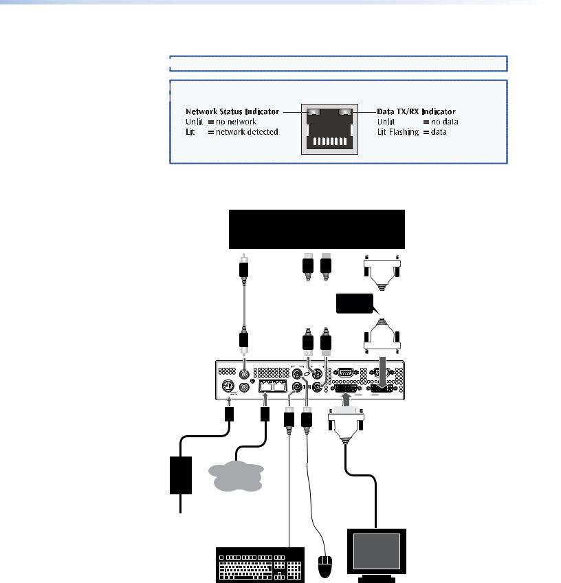
 TIP: With the VNC 200 powered and connected to a network, the Network
  Status Indicator (next to the network connector) should be lit, as follows:
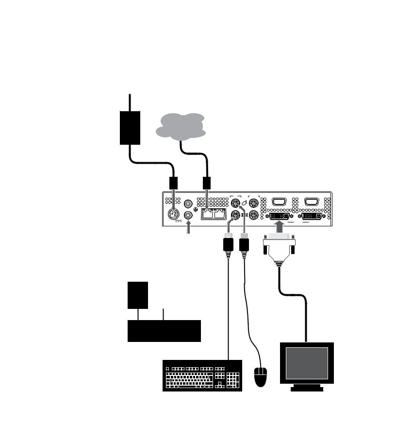
Connecting a digital source
SOURCE COMPUTER
SPDIF audio out |
mouse keyboard |
DVI monitor out |
||
|
|
|
|
|
|
|
|
|
|
Phono |
PS/2 |
IMPORTANT! |
|
DVI-D |
|||
to |
to |
Fit clip-on ferrite |
|
to |
|||
Phono |
PS/2 |
to this end of cable |
|
DVI-D |
|||
|
|
|
|
|
|
|
|
|
|
|
|
|
|
|
|
|
|
|
|
|
|
|
|
VNC 200 (Encoder)
IN |
REMOTE |
IN
POWER
|
|
OUT/ |
|
|
|
|
|
LOOP |
|
|
|
12V DC |
AUDIO |
LAN — 2 |
DVI-I |
IN |
|
5A |
SPDIF |
||||
|
|
|
PSU NETWORK
Power
Source
DVI
MONITOR
Figure 11. Connecting a Digital Source
VN-Matrix 200 Series • Installation |
20 |
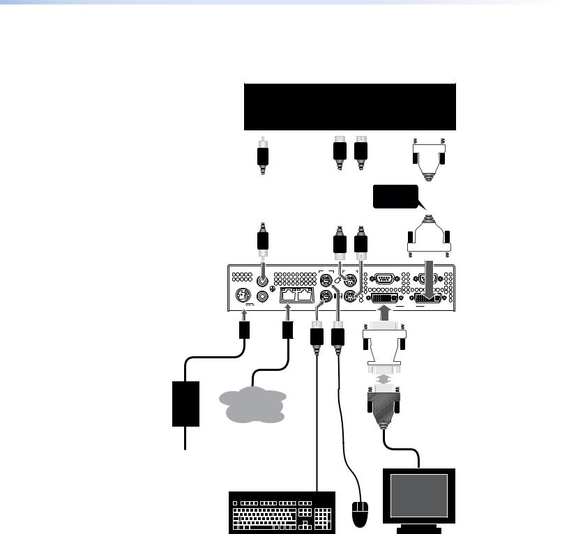
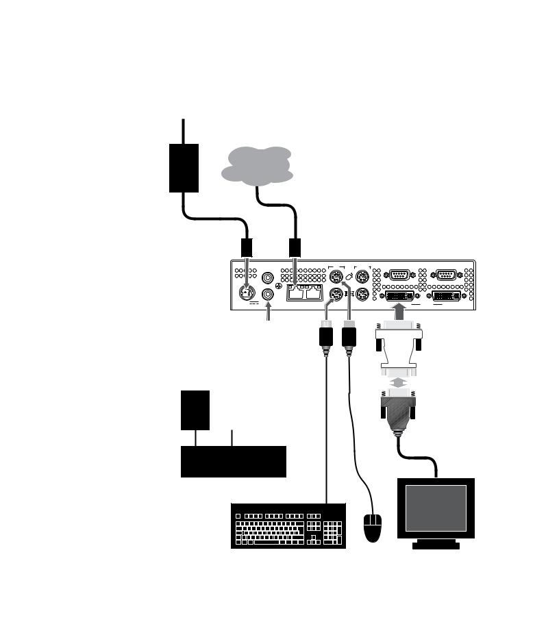
Connecting an analog source
SOURCE COMPUTER
SPDIF audio out |
mouse keyboard |
analog monitor out |
||||
|
|
|
|
|
|
|
|
|
|
|
|
|
|
|
Phono |
|
PS/2 |
|
IMPORTANT! |
|
15-pin |
||||
|
|
|
|
HD-type |
|||||||
|
to |
|
to |
|
Fit clip-on ferrite |
|
|||||
NETWORK |
|
|
|
to |
|||||||
Phono |
|
PS/2 |
|
to this end of cable |
|
||||||
|
|
|
DVI-A |
||||||||
|
|
|
|
|
|
|
|||||
|
|
|
|
|
|
|
|
|
|
|
|
|
|
|
|
|
|
|
|
|
|
|
|
|
|
|
|
|
|
|
|
|
|
|
|
VNC 200 |
|
IN |
REMOTE |
|
|
(Encoder) |
|
IN |
|
|
|
POWER |
|
|
|
|
|
|
|
OUT/ |
|
|
|
|
|
LOOP |
|
|
|
12V DC |
AUDIO |
LAN — 2 |
DVI-I |
IN |
|
5A |
SPDIF |
||||
|
|
|
DVI-A to 15-pin HD-type Adapter
PSU NETWORK
Power
Source
ANALOG
MONITOR
Figure 12. Connecting an Analog Source
VN-Matrix 200 Series • Installation |
21 |
Connecting a digital display
Power
Source
PSU NETWORK
VNC 200 (Decoder)
IN |
TO PC |
REMOTE |
RS-232 |
IN 


 OVER LAN
OUT/
LOOP
12V DC |
1 — LAN — 2 |
DVI-I |
IN |
|
5A MAX |
||||
|
|
|
Phono
to
Phono
SPDIF audio in
AMPLIFIER
DVI
DISPLAY
Figure 13. Connecting a Digital Display
 NOTE: The VNC 200 provides both an analog and digital output signal regardless
  of the original source format.
VN-Matrix 200 Series • Installation |
22 |
Connecting an analog display
Power
Source
PSU NETWORK
VNC 200 (Decoder)
IN |
TO PC |
REMOTE |
RS-232 |
|
IN |
|
|
|
|
|
|
OVER LAN |
|
|
OUT/ |
|
|
|
|
LOOP |
|
|
|
12V DC |
1 — LAN — 2 |
DVI-I |
IN |
|
5A MAX |
||||
|
|
|
DVI-A to 15-pin HD-type Adapter
Phono
to
Phono
SPDIF audio in
AMPLIFIER
ANALOG
DISPLAY
Figure 14. Connecting an Analog Display
 NOTE: The VNC 200 provides both an analog and digital output signal regardless
  of the original source format.
VN-Matrix 200 Series • Installation |
23 |

System
Configuration
This section describes the following:
•VNC 200 Web Interface
•Configuring a VNC 200 as an Encoder (Source)
•Configuring a VNC 200 as a Decoder (Display)
•Troubleshooting
VNC 200 Web Interface
Once all VNC 200 devices have been correctly set up for (and connected to) a network, any further system configuration is achieved via the VNC 200 web interface. This contains a number of pages which provide access to various system parameters.
 TIP: This section provides step-by-step instructions for using the web interface and
is aimed at new users of the VNC 200 system. Advanced users may wish to see Technical Data.
The web interface is “served up” by the VNC 200 device that was designated as the controller during the network setup procedure (see “Setup and Connection Procedure”). It can be viewed by any up-to-date web browser, running on a PC or a laptop that is connected to the same network as the VNC 200 devices.
Suitable browsers include, but are not limited to:
•Microsoft® Internet Explorer (v6 and above)
•Firefox®, Mozilla® (v1.3 and above)
 NOTE: Whatever browser is used, it must be configured to accept cookies and
be JavaScript-enabled. For further help on configuring your browser, see “Browser Configuration”.
Accessing the web interface
1.Enter the IP address of the controller device into the address bar of the web browser, for example, http://192.168.0.18. The following web page illustration appears in the web browser.
VN-Matrix 200 Series • System Configuration |
24 |
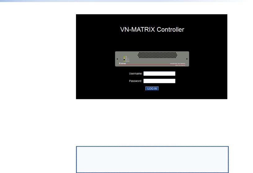
Figure 15. VN-MATRIX Controller Log In Screen
2.Enter the appropriate username and password. The VNC 200 has two user accounts:
•admin — Allows full read and write access to all setup parameters.
•public — Allows read only access to setup parameters.
NOTES: • |
As shipped from the factory, the password for both accounts is |
|
the same as the username (the password is “admin” for the |
|
administrator account and “public” for the public account). |
• |
The username and password are case sensitive. |
• |
For intial setup, use the admin username. |
Initially, the password for both accounts is the same as the username (that is, the account name). It is recommended that these passwords be changed after logging in (see “Changing User Login Passwords”).
3.Click the Log In button. If the login details are correct the Device List page will appear (see the next section).
VN-Matrix 200 Series • System Configuration |
25 |
 Loading...