


 Loading...
VoiceLift™ Microphone
Installation Guide for VLM 1000 and VLM 2000
68-1629-01
Rev. A
01 09

Precautions
Safety Instructions • English
This symbol is intended to alert the user of important operating and maintenance (servicing) instructions in the literature provided with the equipment.
This symbol is intended to alert the user of the presence of uninsulated dangerous voltage within the product’s enclosure that may present a risk of electric shock.
Caution
Read Instructions • Read and understand all safety and operating instructions before using the equipment. Retain Instructions • The safety instructions should be kept for future reference.
Follow Warnings • Follow all warnings and instructions marked on the equipment or in the user information.
Avoid Attachments • Do not use tools or attachments that are not recommended by the equipment manufacturer because they may be hazardous.
Consignes de Sécurité • Français
Ce symbole sert à avertir l’utilisateur que la documentation fournie avec le matériel contient des instructions importantes concernant l’exploitation et la maintenance (réparation).
Ce symbole sert à avertir l’utilisateur de la présence dans le boîtier de l’appareil de tensions dangereuses non isolées posant des risques d’électrocution.
Attention
Lire les instructions• Prendre connaissance de toutes les consignes de sécurité et d’exploitation avant d’utiliser le matériel.
Conserver les instructions• Ranger les consignes de sécurité afin de pouvoir les consulter à l’avenir.
Respecter les avertissements • Observer tous les avertissements et consignes marqués sur le matériel ou présentés dans la documentation utilisateur.
Eviter les pièces de fixation • Ne pas utiliser de pièces de fixation ni d’outils non recommandés par le fabricant du matériel car cela risquerait de poser certains dangers.
Sicherheitsanleitungen • Deutsch
Dieses Symbol soll dem Benutzer in der im Lieferumfang enthaltenen Dokumentation besonders wichtige Hinweise zur Bedienung und Wartung (Instandhaltung) geben.
Dieses Symbol soll den Benutzer darauf aufmerksam machen, daß im Inneren des Gehäuses dieses Produktes gefährliche Spannungen, die nicht isoliert sind und die einen elektrischen Schock verursachen können, herrschen.
Achtung
Lesen der Anleitungen • Bevor Sie das Gerät zum ersten Mal verwenden, sollten Sie alle Sicherheits-und Bedienungsanleitungen genau durchlesen und verstehen.
Aufbewahren der Anleitungen • Die Hinweise zur elektrischen Sicherheit des Produktes sollten Sie aufbewahren, damit Sie im Bedarfsfall darauf zurückgreifen können.
Befolgen der Warnhinweise • Befolgen Sie alle Warnhinweise und Anleitungen auf dem Gerät oder in der Benutzerdokumentation.
Keine Zusatzgeräte • Verwenden Sie keine Werkzeuge oder Zusatzgeräte, die nicht ausdrücklich vom Hersteller empfohlen wurden, da diese eine Gefahrenquelle darstellen können.
Instrucciones de seguridad • Español
Este símbolo se utiliza para advertir al usuario sobre instrucciones importantes de operación y mantenimiento (o cambio de partes) que se desean destacar en el contenido de la documentación suministrada con los equipos.
Este símbolo se utiliza para advertir al usuario sobre la presencia de elementos con voltaje peligroso sin protección aislante, que puedan encontrarse dentro de la caja o alojamiento del producto, y que puedan representar riesgo de electrocución.
Precaucion
Leer las instrucciones • Leer y analizar todas las instrucciones de operación y seguridad, antes de usar el equipo.
Conservar las instrucciones • Conservar las instrucciones de seguridad para futura consulta.
Obedecer las advertencias • Todas las advertencias e instrucciones marcadas en el equipo o en la documentación del usuario, deben ser obedecidas.
Evitar el uso de accesorios • No usar herramientas o accesorios que no sean especificamente recomendados por el fabricante, ya que podrian implicar riesgos.
•


••
••
Warning
Power sources • This equipment should be operated only from the power source indicated on the product. This equipment is intended to be used with a main power system with a grounded (neutral) conductor. The third (grounding) pin is a safety feature, do not attempt to bypass or disable it.
Power disconnection • To remove power from the equipment safely, remove all power cords from the rear of the equipment, or the desktop power module (if detachable), or from the power source receptacle (wall plug).
Power cord protection • Power cords should be routed so that they are not likely to be stepped on or pinched by items placed upon or against them.
Servicing • Refer all servicing to qualified service personnel. There are no user-serviceable parts inside. To prevent the risk of shock, do not attempt to service this equipment yourself because opening or removing covers may expose you to dangerous voltage or other hazards.
Slots and openings • If the equipment has slots or holes in the enclosure, these are provided to prevent overheating of sensitive components inside. These openings must never be blocked by other objects.
Lithium battery • There is a danger of explosion if battery is incorrectly replaced. Replace it only with the same or equivalent type recommended by the manufacturer. Dispose of used batteries according to the manufacturer’s instructions.
Avertissement
Alimentations• Ne faire fonctionner ce matériel qu’avec la source d’alimentation indiquée sur l’appareil. Ce matériel doit être utilisé avec une alimentation principale comportant un fil de terre (neutre). Le troisième contact (de mise à la terre) constitue un dispositif de sécurité : n’essayez pas de la contourner ni de la désactiver.
Déconnexion de l’alimentation• Pour mettre le matériel hors tension sans danger, déconnectez tous les cordons d’alimentation de l’arrière de l’appareil ou du module d’alimentation de bureau (s’il est amovible) ou encore de la prise secteur.
Protection du cordon d’alimentation • Acheminer les cordons d’alimentation de manière à ce que personne ne risque de marcher dessus et à ce qu’ils ne soient pas écrasés ou pincés par des objets.
Réparation-maintenance • Faire exécuter toutes les interventions de réparation-maintenance par un technicien qualifié. Aucun des éléments internes ne peut être réparé par l’utilisateur. Afin d’éviter tout danger d’électrocution, l’utilisateur ne doit pas essayer de procéder lui-même à ces opérations car l’ouverture ou le retrait des couvercles risquent de l’exposer à de hautes tensions et autres dangers.
Fentes et orifices • Si le boîtier de l’appareil comporte des fentes ou des orifices, ceux-ci servent à empêcher les composants internes sensibles de surchauffer. Ces ouvertures ne doivent jamais être bloquées par des objets.
Lithium Batterie • Il a danger d’explosion s’ll y a remplacment incorrect de la batterie. Remplacer uniquement avec une batterie du meme type ou d’un ype equivalent recommande par le constructeur. Mettre au reut les batteries usagees conformement aux instructions du fabricant.
Vorsicht
Stromquellen • Dieses Gerät sollte nur über die auf dem Produkt angegebene Stromquelle betrieben werden. Dieses Gerät wurde für eine Verwendung mit einer Hauptstromleitung mit einem geerdeten (neutralen) Leiter konzipiert. Der dritte Kontakt ist für einen Erdanschluß, und stellt eine Sicherheitsfunktion dar. Diese sollte nicht umgangen oder außer Betrieb gesetzt werden.
Stromunterbrechung • Um das Gerät auf sichere Weise vom Netz zu trennen, sollten Sie alle Netzkabel aus der Rückseite des Gerätes, aus der externen Stomversorgung (falls dies möglich ist) oder aus der Wandsteckdose ziehen.
Schutz des Netzkabels • Netzkabel sollten stets so verlegt werden, daß sie nicht im Weg liegen und niemand darauf treten kann oder Objekte daraufoder unmittelbar dagegengestellt werden können.
Wartung • Alle Wartungsmaßnahmen sollten nur von qualifiziertem Servicepersonal durchgeführt werden. Die internen Komponenten des Gerätes sind wartungsfrei. Zur Vermeidung eines elektrischen Schocks versuchen Sie in keinem Fall, dieses Gerät selbst öffnen, da beim Entfernen der Abdeckungen die Gefahr eines elektrischen Schlags und/oder andere Gefahren bestehen.
Schlitze und Öffnungen • Wenn das Gerät Schlitze oder Löcher im Gehäuse aufweist, dienen diese zur Vermeidung einer Überhitzung der empfindlichen Teile im Inneren. Diese Öffnungen dürfen niemals von anderen Objekten blockiert werden.
Litium-Batterie • Explosionsgefahr, falls die Batterie nicht richtig ersetzt wird. Ersetzen Sie verbrauchte Batterien nur durch den gleichen oder einen vergleichbaren Batterietyp, der auch vom Hersteller empfohlen wird. Entsorgen Sie verbrauchte Batterien bitte gemäß den Herstelleranweisungen.
Advertencia
Alimentación eléctrica • Este equipo debe conectarse únicamente a la fuente/tipo de alimentación eléctrica indicada en el mismo. La alimentación eléctrica de este equipo debe provenir de un sistema de distribución general con conductor neutro a tierra. La tercera pata (puesta a tierra) es una medida de seguridad, no puentearia ni eliminaria.
Desconexión de alimentación eléctrica • Para desconectar con seguridad la acometida de alimentación eléctrica al equipo, desenchufar todos los cables de alimentación en el panel trasero del equipo, o desenchufar el módulo de alimentación (si fuera independiente), o desenchufar el cable del receptáculo de la pared.
Protección del cables de alimentación • Los cables de alimentación eléctrica se deben instalar en lugares donde no sean pisados ni apretados por objetos que se puedan apoyar sobre ellos.
Reparaciones/mantenimiento • Solicitar siempre los servicios técnicos de personal calificado. En el interior no hay partes a las que el usuario deba acceder. Para evitar riesgo de electrocución, no intentar personalmente la reparación/mantenimiento de este equipo, ya que al abrir o extraer las tapas puede quedar expuesto a voltajes peligrosos u otros riesgos.
Ranuras y aberturas • Si el equipo posee ranuras o orificios en su caja/alojamiento, es para evitar el sobrecalientamiento de componentes internos sensibles. Estas aberturas nunca se deben obstruir con otros objetos.
Batería de litio • Existe riesgo de explosión si esta batería se coloca en la posición incorrecta. Cambiar esta batería únicamente con el mismo tipo (o su equivalente) recomendado por el fabricante. Desachar las baterías usadas siguiendo las instrucciones del fabricante.
•
•
•
•
•
•
Introduction — Overview
FCC Class B Notice
This equipment has been tested and found to comply with the limits for a Class B digital device, pursuant to part 15 of the FCC Rules. These limits are designed to provide reasonable protection against harmful interference in a residential installation. This equipment generates, uses and can radiate radio frequency energy and, if not installed and used in accordance with the instructions, may cause harmful interference to radio communications. However, there is no guarantee that the interference will not occur in a particular installation. If this equipment does cause harmful interference to radio or television reception, which can be determined by turning the equipment off and on, the user is encouraged to try to correct the interference by one or more of the following measures:
•Reorient or relocate the receiving antenna.
•Increase the separation between the equipment and receiver.
•Connect the equipment into an outlet on a circuit different from that to which the receiver is connected.
•Consult the dealer or an experienced radio/TV technician for help.
About This Guide
This manual covers the installation of the Extron VoiceLift™ Microphone as part of an Extron PoleVault™ system. The VoiceLift VLR 102 receiver can be installed in a drop ceiling, a standard junction box, an octagonal ceiling box, or on a wall. It is assumed that the installer has some knowledge of and experience with A/V, electrical, or electronic device installation. This manual guides the A/V installer through the steps to install and connect each component of the system.
The VoiceLift Microphone
The Extron VoiceLift Microphone is an easy-to-use, low-power, classroom amplification system that ensures the teacher can be clearly heard at a comfortable level throughout the classroom. Speech is picked up by the pendant microphone worn by the teacher and is transmitted wirelessly to a base station receiver. The signal is then fed to the PVS 204SA PoleVault Switcher, which powers strategically placed loudspeakers to improve the signal-to-noise ratio of the teacher's voice above ambient noise level.
SI 3C LP
Plenum Full-Range
Ceiling Speakers
|
Free |
|
GlobalViewer |
VoiceLift |
Software |
|
|
Receiver |
|
|
TCP/IP |
|
Network |
|
PVS 204SA |
PoleVault®
Switcher / Amplifier
Pendant
Microphone
|
VIDEO |
AY |
|
DISPL |
AUX |
OFF |
VIDEO |
ON |
|
|
PC |
VOLUME |
IMAGE |
|
|
|
MUTE |
|
IP Plus |
|
104 |
|
MLC |
MLC 104 IP Plus
MediaLink
Controller
VoiceLift Microphone installation and wiring overview
VoiceLift Microphone Installation • Introduction — Overview |
1-1 |
Introduction — Planning
Before You Begin — Planning the Installation
Before starting installation, you must consider several major factors to ensure that the installation of the VoiceLift
Microphone is as smooth and trouble free as possible, and that the result meets the needs of the users. Placement of the receiver (sensor location) is very important for optimal performance of the VoiceLift Microphone. Because
IR technology requires line-of-sight placement, take into consideration anything that could impact or block the transmission of the IR signal from the microphone to the receiver.
The lists on the following pages, though not comprehensive, should be consulted to help ensure that key aspects have been considered.
1.Room layout
The application diagram below shows a typical classroom installation incorporating the VoiceLift Microphone.
VLP 102
Pendant
Microphone
|
|
SI 3C LP |
VLR 102 |
|
|
Plenum Full-Range |
Receiver |
|
|
|
|
TCP/IP |
|
Ceiling Speakers |
|
|
|
|
|
Network |
|
VLC 102 |
|
|
|
||
|
|
|
|
|
|
Desktop Charging |
|
|
|
Station |
|
Typical classroom installation
NDue to the operating frequencies of the microphone and receiver, lighting fixtures such as fluorescent lights and plasma displays should not affect performance of the system.
1-2 VoiceLift Microphone Installation • Introduction — Planning
Room considerations
Room factors to be considered should include, but are not confined to:
•Room configuration
Room size, orientation, and layout
Location of windows, doors, skylights, etc., for potential light interference
Alcoves, bays, or sheltered areas
Location of any dark or covered walls (Dark surfaces reduce reflection of the IR signal.)
–Wall art
–Curtains/blinds
–Acoustical panels
–Wall material/texture
•Line-of-sight obstructions between microphone and receiver
Existing movable furniture (desks, tables, podiums)
Existing installed furniture (bookcases, racks, cabinets, workbenches, sinks, etc.)
Support pillars
Projector
•Ceiling and wall type (important in assessing the installation hardware needed)
Ceiling type (drop, spline, hard lid, etc.); structural type (wood, concrete, trusses)
Wall type (drywall, cement, brick, etc.)
•Receiver location
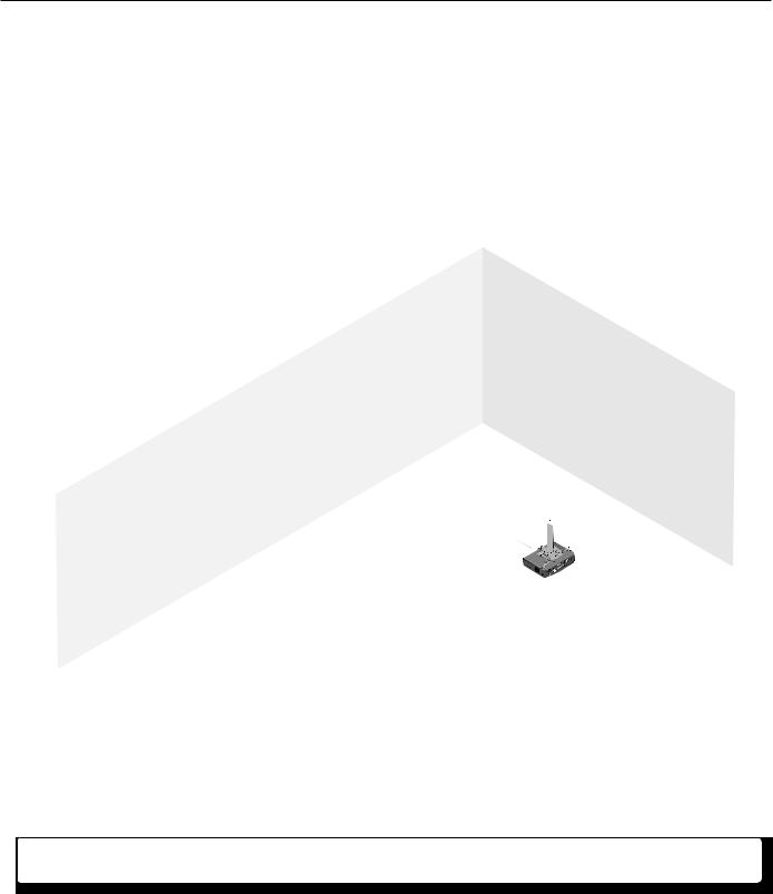
Best location: on the ceiling, at the middle of the classroom
If ceiling mounting is not possible, place high and centered on the longest wall.
Locations to avoid:
–Places where line of sight could be obstructed; e.g., too close to the projector
–Corners of the room
–On walls, at less than 6' or more than 12' up from the base
–Areas that receive direct sunlight
PVT A/V Wallplate Location
|
|
|
|
|
|
|
|
|
|
|
|
|
|
Screen/White |
Teacher’s Desk |
||||||||||||||||||||||||
|
|
|
|
|
|
|
|
|
|
|
|
|
|
Board Location |
|||||||||||||||||||||||||
Potential |
|
|
|
|
|
|
|
|
|
|
|
|
|
|
|
|
|
|
|
|
|
||||||||||||||||||
TV / VCR / DVD |
|
|
|
|
|
|
|
|
|||||||||||||||||||||||||||||||
VLR 102 IR |
|
|
|
|
|
|
|
|
|||||||||||||||||||||||||||||||
Inputs |
|
|
|
|
|
|
|
|
|||||||||||||||||||||||||||||||
Receiver |
|
|
|
|
|
|
|
|
|
|
|
|
|
|
|
|
|
|
|
|
|
|
|
|
|
|
|
|
|
|
|
|
|
|
|
|
|
|
|
Locations |
|
|
|
|
|
|
|
|
|
|
|
|
|
|
|
|
|
|
|
|
|
|
|
|
|
|
|
|
|
|
|
|
|
|
|
|
|
|
|
|
|
|
|
|
|
|
|
|
|
|
|
|
|
|
|
|
|
|
|
|
|
|
|
|
|
|
|
|
|
|
|
|
|
|
|
|
|
|
|
|
|
|
|
|
|
|
|
|
|
|
|
|
|
|
|
|
|
|
|
|
|
|
|
|
|
|
|
|
|
|
|
|
|
|
|
|
|
|
|
|
|
|
|
|
|
|
|
|
|
|
|
|
|
|
|
|
|
|
|
|
|
|
|
|
|
|
|
|
|
|
|
|
|
|
|
|
|
|
|
|
|
|
|
|
|
|
|
|
|
|
|
|
|
|
|
|
|
|
|
|
|
|
|
|
|
|
|
|
|
|
|
|
|
|
|
|
|
|
|
|
|
|
|
|
|
|
|
|
|
|
|
|
|
|
|
|
|
|
|
|
|
|
|
|
|
|
|
|
|
|
|
|
|
|
|
|
|
|
|
|
|
|
|
|
|
|
|
|
|
|
|
|
|
|
|
|
|
|
|
|
|
|
|
|
|
|
|
|
|
|
|
|
|
|
|
|
|
|
|
|
|
|
|
|
|
|
|
|
|
|
|
|
|
|
|
|
|
|
|
|
|
|
|
|
|
|
|
|
|
|
|
|
|
|
|
|
|
|
|
|
|
|
|
|
|
|
|
|
|
|
|
|
|
|
|
|
|
|
|
|
|
|
|
|
|
|
|
|
|
|
|
|
|
|
|
|
|
|
|
|
|
|
|
|
|
|
|
|
|
|
|
|
|
|
|
|
|
|
|
|
|
|
|
|
|
|
|
|
|
|
|
|
|
|
|
|
|
|
|
|
|
|
|
|
|
|
|
|
|
|
|
|
|
|
|
|
|
|
|
|
|
|
|
|
|
|
|
|
|
|
|
|
|
|
|
|
|
|
|
|
|
|
|
|
|
|
|
|
|
|
|
|
|
|
|
|
|
|
|
|
|
|
|
|
|
|
|
|
|
|
|
|
|
|
|
|
|
|
|
|
|
|
|
|
|
|
|
|
|
|
|
|
|
|
|
|
|
|
|
|
|
|
|
|
|
|
|
|
|
|
|
|
|
|
|
|
|
|
|
|
|
|
|
|
|
|
|
|
|
|
|
|
|
|
|
|
|
|
|
|
|
|
|
|
|
|
|
|
|
|
|
|
|
|
|
|
|
|
|
Student Desks
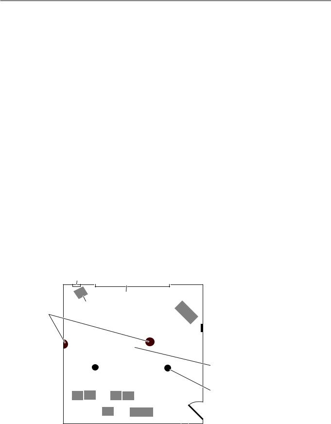
Example of a classroom installation
MLC Controller
 Location
Projector/
Switcher
Location
Speaker
Locations
VoiceLift Microphone Installation • Introduction — Planning |
1-3 |
Introduction — Planning, cont’d
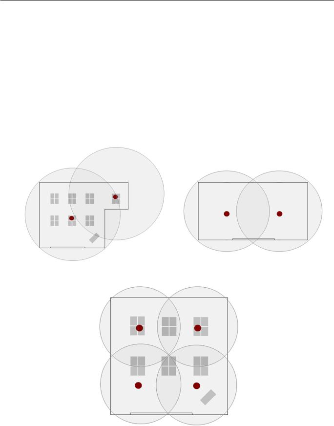
•Optional VLR 102SR Secondary receiver. One or more secondary receivers (VLR 102 SR) may be needed if any of the following conditions exist:
The room is larger than 40' by 40'.
Obstructions exist between the microphone and the receiver.
The room is odd-shaped, e.g., L-shaped or long.
The room has recessed or sheltered areas, such as alcoves or bays.
The room has large windows or windows on multiple walls.
Portions of the walls are dark and/or covered. Dark surfaces reduce signal reflection. Take the following into consideration:
–Wall art
–Curtains/blinds
–Acoustical panels
–Wall material/texture
The following diagrams show examples of secondary receiver placement.
Receiver and one secondary receiver in an odd-shaped room
Receiver and one secondary receiver in a long room
Receiver and three secondary receivers in a large room, or a room with dark walls, obstructions, and/or windows
1-4 VoiceLift Microphone Installation • Introduction — Planning

Introduction — Inventory Overview
2.Inventory
a.Included items
The VoiceLift Microphone is shipped in one box and is available in two package configurations:
•VLM 1000 (part #42-139-01): one VLP 102 pendant microphone, a VLR 102 Receiver, and a wall charger.
•VLM 2000 (part #42-139-02): two VLP 102 pendant microphones, a VLR 102 Receiver, and a VLC 102 charging station.
Carefully check all the received items against the following inventory lists.
VoiceLift Microphone Devices and Hardware
VLM 1000 VoiceLift Microphone |
VLM 2000 VoiceLift Microphone |
#42-139-01 |
#42-139-02 |
PWR
Extron |
CHARGE |
|
ON |
||
|
||
|
OFF/MUTE/CHG |
VLP 102 |
VLR 102 |
Pendant Microphone |
IR Receiver |
Adapter
Wall Charger/
Power Supply
AA Rechargeable |
|
|
Battery |
Lanyard |
|
|
|
|
Z Bracket |
|
|
and Screw |
|
|
|
15’ Ethernet Cable |
|
VLP 102 Pendant Microphone |
Battery, AA 2500mAh |
|
VLR 102 IR Receiver |
Lanyard |
|
RJ-45 to C/S adapter |
Z bracket |
|
Wall charger/power supply |
Z bracket screw |
|
Ethernet cable, 15 ft. |
|
|
|
PWR |
|
PWR |
|
Extron |
CHARGE |
Extron |
CHARGE |
|
ON |
ON |
|||
|
|
|||
|
OFF/MUTE/CHG |
|
OFF/MUTE/CHG |
|
VLR 102 |
VLP 102 |
IR Receiver |
Pendant Microphones (2) |
|
VLC 102 |
Adapter |
|
|
Charging Station |
|
Z Bracket
and Screw
|
|
Lanyard (2) |
Wall Charger/ |
|
|
Power Supply |
AA Rechargeable |
|
|
15’ Ethernet Cable |
|
|
Batteries (2) |
|
VLP 102 Pendant Microphones (2) |
Ethernet cable, 15 ft. |
|
VLR 102 IR Receiver |
Batteries, AA 2500mAh (2) |
|
VLC 102 Charging Station |
Lanyard (2) |
|
RJ-45 to C/S adapter |
Z bracket |
|
Wall charger/power supply |
Z bracket screw |
|
VoiceLift Microphone Installation • Introduction — Inventory Overview |
1-5 |

Introduction — Inventory Overview, cont’d
NIf any items in the VoiceLift Microphone boxes are damaged or missing, contact the Extron Technical Hotline (see rear cover for contact numbers).
b. Items not included
The following items are not included. However, some or all of these items may be needed for the installation at your particular site.
•Additional length of RJ-45 cabling (CAT 5, 5e, or 6 with T568A or T568B straight-through wiring)
•Installation hardware (may vary by installation):
Electrical ceiling box, 3.5" or 4.0"
Junction box
Plaster ring
Raceway
Bolts for concrete structural ceilings where needed
Dry wall anchors and screws
Spare ceiling tiles in case of accidental damage during installation
Safety wire, lag eye bolts, and strain reliefs
Heat shrink, extension cord c. Optional items
The optional items suggested below can be added to or substituted for items in the standard VoiceLift Microphone kit.
•VLR 102 SR Secondary VoiceLift Receiver
•VLC 102 Charging Station
•VLP 102 pendant microphone (additional)
•Wall charger
•Headset microphone
•Lapel microphone
•Lanyard
•Lanyard clip
•IPL T S1 Ethernet Control Interface d. Installation tools:
•Tape measure
•Screwdriver set and Tweeker
•Hole saw, keyhole saw, or razor knife
•Appropriate drill and bit set for the mounting surface
•Stud finder
•Flashlight
•Safety goggles
•RJ-45 crimpers and connectors (plenum rated, if applicable)
•Zip ties
•Vacuum cleaner
1-6 |
VoiceLift Microphone Installation • Introduction — Inventory Overview |
Installation — Overview
NFor operation and setup of other Extron PoleVault system components mentioned in this guide, refer to the appropriate user manual provided with each product.
This overview outlines the basic steps for installing the VLR 102 VoiceLift Receiver. Detailed descriptions with illustrations of these steps are provided in three sections, stages One through Three. If VLR 102 SR Secondary
Receiver(s) are being used with your system, this installation procedure applies to them as well.
N
•Additional installation hardware is needed for this installation, and should be supplied by the installer. See
“Items not included,” in chapter 1, “Introduction,” for a list of items that you may need.
•Optional accessories may be desired for this installation. See “Optional items”, in chapter 1, “Introduction,” for a list of available accessories, or visit www.extron.com for details.
•Refer to local building standards and codes to verify that the installation will meet all the regulatory requirements.
•Observe all local and national building and safety codes, UL requirements, and ADA Accessibility Guidelines.
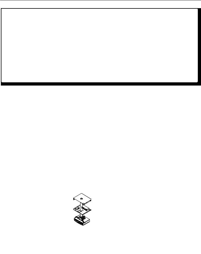
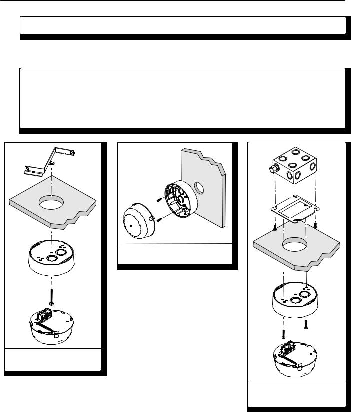
Mounting the VoiceLift receiver to a wall
Mounting the VoiceLift receiver in a drop ceiling.
Mounting the VoiceLift receiver in a junction box
The following pages contain instructions for installing the VLR 102 IR Receiver. Where possible, line drawings and photos from an actual installation are used to clarify some of the steps discussed in the text. Each image has a number corresponding to the step that is being described (e.g., Ñ).
VoiceLift Microphone Installation • Installation — Overview |
2-1 |
Loading...