


 Loading...
User Guide
IP Link®
IPL T PC1
IPL T PC1i
IP Link Power Control Interfaces
68-738-10 Rev. B
09 11

Safety Instructions • English
This symbol is intended to alert the user of important operating and maintenance (servicing) instructions in the literature provided with the equipment.
This symbol is intended to alert the user of the presence of uninsulated dangerous voltage within the product’s enclosure that may present a risk of electric shock.
Caution
Read Instructions • Read and understand all safety and operating instructions before using the equipment. Retain Instructions • The safety instructions should be kept for future reference.
Follow Warnings • Follow all warnings and instructions marked on the equipment or in the user information.
Avoid Attachments • Do not use tools or attachments that are not recommended by the equipment manufacturer because they may be hazardous.
Warning
Power sources • This equipment should be operated only from the power source indicated on the product. This equipment is intended to be used with a main power system with a grounded (neutral) conductor. The third (grounding) pin is a safety feature, do not attempt to bypass or disable it.
Power disconnection • To remove power from the equipment safely, remove all power cords from the rear of the equipment, or the desktop power module (if detachable), or from the power source receptacle (wall plug).
Power cord protection • Power cords should be routed so that they are not likely to be stepped on or pinched by items placed upon or against them.
Servicing • Refer all servicing to qualified service personnel. There are no user-serviceable parts inside. To prevent the risk of shock, do not attempt to service this equipment yourself because opening or removing covers may expose you to dangerous voltage or other hazards.
Slots and openings • If the equipment has slots or holes in the enclosure, these are provided to prevent overheating of sensitive components inside. These openings must never be blocked by other objects.
Lithium battery • There is a danger of explosion if battery is incorrectly replaced. Replace it only with the same or equivalent type recommended by the manufacturer. Dispose of used batteries according to the manufacturer instructions.
Consignes de Sécurité • Français
Ce symbole sert à avertir l’utilisateur que la documentation fournie avec le matériel contient des instructions importantes concernant l’exploitation et la maintenance (réparation).
Ce symbole sert à avertir l’utilisateur de la présence dans le boîtier de l’appareil de tensions dangereuses non isolées posant des risques d’électrocution.
Attention
Lire les instructions• Prendre connaissance de toutes les consignes de sécurité et d’exploitation avant d’utiliser le matériel.
Conserver les instructions• Ranger les consignes de sécurité afin de pouvoir les consulter à l’avenir.
Respecter les avertissements • Observer tous les avertissements et consignes marqués sur le matériel ou présentés dans la documentation utilisateur.
Eviter les pièces de fixation • Ne pas utiliser de pièces de fixation ni d’outils non recommandés par le fabricant du matériel car cela risquerait de poser certains dangers.
Avertissement
Alimentations • Ne faire fonctionner ce matériel qu’avec la source d’alimentation indiquée sur l’appareil. Ce matériel doit être utilisé avec une alimentation principale comportant un fil de terre (neutre). Le troisième contact (de mise à la terre) constitue un dispositif de sécurité : n’essayez pas de la contourner ni de la désactiver.
Déconnexion de l’alimentation• Pour mettre le matériel hors tension sans danger, déconnectez tous les cordons d’alimentation de l’arrière de l’appareil ou du module d’alimentation de bureau (s’il est amovible) ou encore de la prise secteur.
Protection du cordon d’alimentation • Acheminer les cordons d’alimentation de manière à ce que personne ne risque de marcher dessus et à ce qu’ils ne soient pas écrasés ou pincés par des objets.
Réparation-maintenance • Faire exécuter toutes les interventions de réparation-maintenance par un technicien qualifié. Aucun des éléments internes ne peut être réparé par l’utilisateur. Afin d’éviter tout danger d’électrocution, l’utilisateur ne doit pas essayer de procéder lui-même à ces opérations car l’ouverture ou le retrait des couvercles risquent de l’exposer à de hautes tensions et autres dangers.
Fentes et orifices • Si le boîtier de l’appareil comporte des fentes ou des orifices, ceux-ci servent à empêcher les composants internes sensibles de surchauffer. Ces ouvertures ne doivent jamais être bloquées par des objets.
Lithium Batterie • Il a danger d’explosion s’ll y a remplacment incorrect de la batterie. Remplacer uniquement avec une batterie du meme type ou d’un ype equivalent recommande par le constructeur. Mettre au reut les batteries usagees conformement aux instructions du fabricant.
Sicherheitsanleitungen • Deutsch
Dieses Symbol soll dem Benutzer in der im Lieferumfang enthaltenen Dokumentation besonders wichtige Hinweise zur Bedienung und Wartung (Instandhaltung) geben.
Dieses Symbol soll den Benutzer darauf aufmerksam machen, daß im Inneren des Gehäuses dieses Produktes gefährliche Spannungen, die nicht isoliert sind und die einen elektrischen Schock verursachen können, herrschen.
Achtung
Lesen der Anleitungen • Bevor Sie das Gerät zum ersten Mal verwenden, sollten Sie alle Sicherheits-und Bedienungsanleitungen genau durchlesen und verstehen.
Aufbewahren der Anleitungen • Die Hinweise zur elektrischen Sicherheit des Produktes sollten Sie aufbewahren, damit Sie im Bedarfsfall darauf zurückgreifen können.
Befolgen der Warnhinweise • Befolgen Sie alle Warnhinweise und Anleitungen auf dem Gerät oder in der Benutzerdokumentation.
Keine Zusatzgeräte • Verwenden Sie keine Werkzeuge oder Zusatzgeräte, die nicht ausdrücklich vom Hersteller empfohlen wurden, da diese eine Gefahrenquelle darstellen können.
Vorsicht
Stromquellen • Dieses Gerät sollte nur über die auf dem Produkt angegebene Stromquelle betrieben werden. Dieses Gerät wurde für eine Verwendung mit einer Hauptstromleitung mit einem geerdeten (neutralen) Leiter konzipiert. Der dritte Kontakt ist für einen Erdanschluß, und stellt eine Sicherheitsfunktion dar. Diese sollte nicht umgangen oder außer Betrieb gesetzt werden.
Stromunterbrechung • Um das Gerät auf sichere Weise vom Netz zu trennen, sollten Sie alle Netzkabel aus der Rückseite des Gerätes, aus der externen Stomversorgung (falls dies möglich ist) oder aus der Wandsteckdose ziehen.
Schutz des Netzkabels • Netzkabel sollten stets so verlegt werden, daß sie nicht im Weg liegen und niemand darauf treten kann oder Objekte daraufoder unmittelbar dagegengestellt werden können.
Wartung • Alle Wartungsmaßnahmen sollten nur von qualifiziertem Servicepersonal durchgeführt werden. Die internen Komponenten des Gerätes sind wartungsfrei. Zur Vermeidung eines elektrischen Schocks
versuchen Sie in keinem Fall, dieses Gerät selbst öffnen, da beim Entfernen der Abdeckungen die Gefahr eines elektrischen Schlags und/oder andere Gefahren bestehen.
Schlitze und Öffnungen • Wenn das Gerät Schlitze oder Löcher im Gehäuse aufweist, dienen diese zur Vermeidung einer Überhitzung der empfindlichen Teile im Inneren. Diese Öffnungen dürfen niemals von anderen Objekten blockiert werden.
Litium-Batterie • Explosionsgefahr, falls die Batterie nicht richtig ersetzt wird. Ersetzen Sie verbrauchte Batterien nur durch den gleichen oder einen vergleichbaren Batterietyp, der auch vom Hersteller empfohlen wird. Entsorgen Sie verbrauchte Batterien bitte gemäß den Herstelleranweisungen.
Instrucciones de seguridad • Español
Este símbolo se utiliza para advertir al usuario sobre instrucciones
importantes de operación y mantenimiento (o cambio de partes) que se desean destacar en el contenido de la documentación suministrada con los equipos.
Este símbolo se utiliza para advertir al usuario sobre la presencia de elementos con voltaje peligroso sin protección aislante, que puedan encontrarse dentro de la caja o alojamiento del producto, y que puedan representar riesgo de electrocución.
Precaucion
Leer las instrucciones • Leer y analizar todas las instrucciones de operación y seguridad, antes de usar el equipo.
Conservar las instrucciones • Conservar las instrucciones de seguridad para futura consulta.
Obedecer las advertencias • Todas las advertencias e instrucciones marcadas en el equipo o en la documentación del usuario, deben ser obedecidas.
Evitar el uso de accesorios • No usar herramientas o accesorios que no sean especificamente recomendados por el fabricante, ya que podrian implicar riesgos.
•


••
••
Advertencia
Alimentación eléctrica • Este equipo debe conectarse únicamente a la fuente/tipo de alimentación eléctrica indicada en el mismo. La alimentación eléctrica de este equipo debe provenir de un sistema de distribución general con conductor neutro a tierra. La tercera pata (puesta a tierra) es una medida de seguridad, no puentearia ni eliminaria.
Desconexión de alimentación eléctrica • Para desconectar con seguridad la acometida de alimentación eléctrica al equipo, desenchufar todos los cables de alimentación en el panel trasero del equipo, o desenchufar el módulo de alimentación (si fuera independiente), o desenchufar el cable del receptáculo de la pared.
Protección del cables de alimentación • Los cables de alimentación eléctrica se deben instalar en lugares donde no sean pisados ni apretados por objetos que se puedan apoyar sobre ellos.
Reparaciones/mantenimiento • Solicitar siempre los servicios técnicos de personal calificado. En el interior no hay partes a las que el usuario deba acceder. Para evitar riesgo de electrocución, no intentar personalmente la reparación/mantenimiento de este equipo, ya que al abrir o extraer las tapas puede quedar expuesto a voltajes peligrosos u otros riesgos.
Ranuras y aberturas • Si el equipo posee ranuras o orificios en su caja/alojamiento, es para evitar el sobrecalientamiento de componentes internos sensibles. Estas aberturas nunca se deben obstruir con otros objetos.
Batería de litio • Existe riesgo de explosión si esta batería se coloca en la posición incorrecta. Cambiar esta batería únicamente con el mismo tipo (o su equivalente) recomendado por el fabricante. Desachar las baterías usadas siguiendo las instrucciones del fabricante.
•
•
•
•
•
•

FCC Class A Notice
This equipment has been tested and found to comply with the limits for a Class A digital device, pursuant to part 15 of the FCC Rules. Operation is subject to the following two conditions:
1.This device may not cause harmful interference.
2.This device must accept any interference received, including interference that may cause undesired operation.
The Class A limits are designed to provide reasonable protection against harmful interference when the equipment is operated in a commercial environment. This equipment generates, uses, and can radiate radio frequency energy and, if not installed and used in accordance with the instruction manual, may cause harmful interference to radio communications. Operation of this equipment in a residential area is likely to cause harmful interference, in which case the user will be required to correct the interference at his own expense.
 NOTE: This unit was tested with shielded cables on the peripheral devices. Shielded cables must be used with
the unit to ensure compliance with FCC emissions limits.
For more information on safety guidelines, regulatory compliances, EMI/EMF compliance, accessibility, and  related topics, click here.
iii

Conventions Used in this Guide
Notifications
In this user guide, the following are used:
 WARNING: A warning warns of things or actions that might cause injury, death, or
  other severe consequences.
 CAUTION: A caution indicates a potential hazard to equipment or data.
 NOTE: A note draws attention to important information.
 TIP: A tip provides a suggestion to make working with the application easier.
Software Commands
Commands are written in the fonts shown here:
^AR Merge Scene,,Op1 scene 1,1 ^B 51 ^W^C [01]R000400300004000080000600[02]35[17][03]
E X! *X1&* X2)* X2#* X2! CE}
 NOTE: For commands and examples of computer or device responses mentioned
in this guide, the character “0” is used for the number zero and “O” represents the capital letter “o.”
Computer responses and directory paths that do not have variables are written in the font shown here:
Reply from 208.132.180.48: bytes=32 times=2ms TTL=32 C:\Program Files\Extron
Variables are written in slanted form as shown here: ping xxx.xxx.xxx.xxx —t
SOH R Data STX Command ETB ETX
Selectable items, such as menu names, menu options, buttons, tabs, and field names are written in the font shown here:
From the File menu, select New. Click the OK button.
Copyright
© 2011 Extron Electronics. All rights reserved.
Trademarks
All trademarks mentioned in this guide are the properties of their respective owners.
iv

Contents
Introduction............................................................ |
1 |
About this Guide................................................. |
1 |
About the IPL T PC1............................................ |
1 |
Features.............................................................. |
1 |
Application Diagram............................................ |
3 |
Installation and Rear Panel................................. |
4 |
Installation Overview........................................... |
4 |
Rear Panels.......................................................... |
5 |
Connecting Cables.............................................. |
6 |
RS-232 Port Cabling........................................ |
6 |
Wiring the Local Area Network (LAN) Port....... |
8 |
Wiring for IR Control....................................... |
8 |
Wiring the Contact Input Port.......................... |
9 |
Front Panel Features and Operation............... |
10 |
Front Panel Features ......................................... |
10 |
Setting Up the System Using the Front Panel..... |
11 |
Setting Up Power Control of the Output |
|
Device.......................................................... |
11 |
Front Panel Security Lockout |
|
(Executive Mode).......................................... |
12 |
Resetting........................................................... |
12 |
Mode 1......................................................... |
13 |
Mode 2......................................................... |
13 |
Mode 3......................................................... |
14 |
Mode 4......................................................... |
14 |
Mode 5......................................................... |
14 |
HTML Configuration and Control.................... |
15 |
Configuring the Hardware for Ethernet |
|
Control............................................................. |
15 |
Setting Up and Configuring the PC1 |
|
Using ARP.................................................... |
16 |
Setting Up and Configuring the PC1 |
|
Using a Web Browser................................... |
17 |
Setting Up the Computer for IP |
|
Communication............................................ |
18 |
Configuring the IPL T PC1 Using a Web |
|
Browser........................................................ |
20 |
Using the IPL T PC1 Web Pages......................... |
22 |
Viewing the System Status............................. |
23 |
Using the Configuration Pages...................... |
24 |
Configuring the RS-232 Port and the AC |
|
Receptacle.................................................... |
26 |
Upgrading Firmware...................................... |
32 |
Managing Files.............................................. |
38 |
Custom Web Pages........................................... |
40 |
Server Side Includes (SSIs).............................. |
40 |
Query strings................................................. |
40 |
Accessing and Using Telnet (Port 23).............. |
43 |
Troubleshooting................................................. |
45 |
Power Connections....................................... |
45 |
Network Connections.................................... |
45 |
Global Configurator Software............................ |
46 |
SIS Programming and Control.......................... |
47 |
Host-to-Interface Communication...................... |
47 |
Messages Initiated by the IPL T PC1............... |
47 |
Password Information.................................... |
48 |
Error Responses............................................. |
48 |
Error Response References............................. |
48 |
Using the Command and Response Table.......... |
49 |
Symbol Definitions............................................. |
50 |
Command and Response Table for SIS |
|
Commands ..................................................... |
54 |
Reference Material.............................................. |
62 |
Specifications.................................................... |
62 |
Part Numbers and Accessories........................... |
64 |
Included Parts................................................ |
64 |
Optional Accessories...................................... |
64 |
Mounting the IPL T PC1 Interface...................... |
64 |
Tabletop Use.................................................. |
64 |
Rack Mounting.............................................. |
64 |
Under-desk Mounting.................................... |
65 |
Glossary................................................................. |
67 |
IPL T PC1 • Contents |
v |

IPL T PC1 • Contents vi

Introduction
This section provides an overview of the Extron IPL T PC1 and IPL T PC1i IP Link® Power Control Interfaces, and describes their features features. Topics covered in this section are:
•About this Guide
•About the IPL T PC1
•Features
•Application Diagram
About this Guide
This guide contains information about the Extron IPL T PC1 and IPL T PC1i, including explanations of how to install, configure, and operate them. Unless otherwise specified,
“IPL T PC1” and “PC1” refer to both product versions throughout this guide.
About the IPL T PC1
The IPL T PC1 and IPL T PC1i are Ethernet-based power management devices that can control and schedule AC power on and off. Monitoring of various device conditions is also available with Global Configurator® (GC 3.3) software. The IPL T PC1i is an international version, configured for 220 VAC with an IEC connector.
The PC1 and PC1i ports include a LAN port, a bidirectional RS-232 port, an IR output port, and a contact closure input port. These ports provide integration of power control, serial device control, IR device control, and input sensing in a single device that can be mounted on a rack or behind a display device or kiosk.
The PC1 can be a stand-alone control device or as one of many nodes in a distributed control system environment.
Features
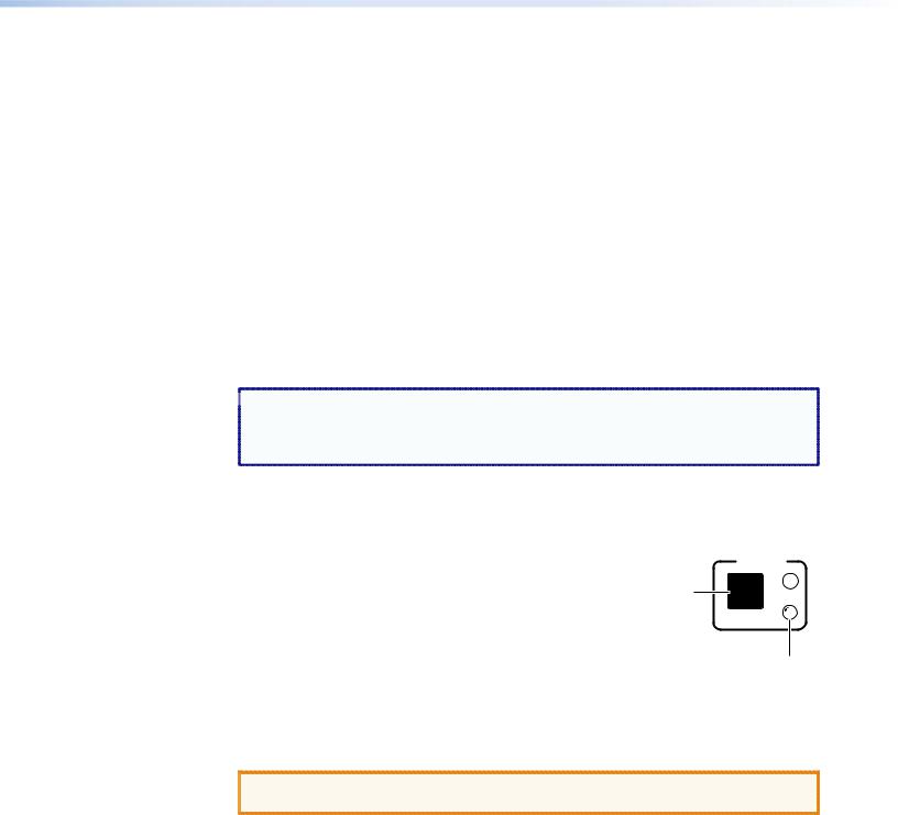
•Remote powering a device on and off — Centralized management features such as Telnet allow remote powering on and off of a plasma display, camera, video conferencing equipment, switcher, or other audio/video device. The Power button on
the front panel lets you turn power on and off to the connected device, while an LED to the lower-right of the Power button lights green to indicate that the device is receiving power.
•RS-232 control — The bidirectional serial port on the rear panel, along with an Extron serial driver, enables RS-232 control of an output device.
•IR control — An IR port on the rear panel enables unidirectional device control via an IR emitter, supported by Extron IR drivers.
•Contact closure input port — This port can detect a closed circuit between an input and ground, and trigger an event that has been set up in GC 3.3 (for example, set off an alarm, turn on a light, or notify you by e-mail that an event has occurred).
IPL T PC1 • Introduction |
1 |

•Industry standard Ethernet protocols — The PC1 uses standard Ethernet and TCP/IP communication protocols, including ARP (Address Resolution Protocol), DHCP (dynamic host configuration protocol), TCP/IP (Transmission Control Protocol/Internet Protocol),
Telnet, and HTTP (HyperText Transfer Protocol).
•Integral high-performance web server — The PC1 has a built-in web server with memory available for storing device drivers, GlobalViewer®, and custom user web pages.
•Configuration utility — Global Configurator software, a free, easy to use Windows®-based configuration utility, makes product setup simple and intuitive; no programming knowledge is required.
•E-mail capabilities to enable support — With e-mail notification, technical support administrators can receive failure and service messages through an e-mail-enabled cell phone, PDA, pager, or Internet e-mail account.
•Web-based A/V asset management — When used with GlobalViewer software, the PC1 provides a powerful, flexible way to manage, monitor, and control a projector, flat panel display, and so on, using a standard Ethernet network.
•Scheduling of power and executive mode — Power to an output device can be scheduled using the web pages, Simple Instruction Set (SIS™) commands, or Global
Configurator. Front panel lockout (executive mode) can also be scheduled by these methods.
•Easy configuration and control — You can easily control the PC1 using:
•The Internet Explorer browser (V5.5 or later)
•A web-based interface
•DataViewer (or a standard Telnet client application)
•Extensive library of device drivers — Device drivers allow Extron products to control various display and source devices, such as projectors, flat-panel displays, and DVD players. Extron has produced thousands of fully tested and uniformly modeled RS-232 and IR device drivers.
•Direct port access — Use existing software programs to control a device that has no Ethernet support. Any existing Extron product with a serial control port can be interfaced with a LAN.
•Built-in multi-level security — You can control access to devices attached to the interface. Two levels of password protection provide appropriate security.
•Simultaneous multi-user support — Each PC1 interface supports multiple concurrent users, improving system throughput.
•Multiple mounting options — The PC1 can be placed on a tabletop, for which four feet are provided and can be attached. Optional hardware for mounting the unit under a desktop or podium or on a rack shelf is not included, but may be ordered separately.
IPL T PC1 • Introduction |
2 |
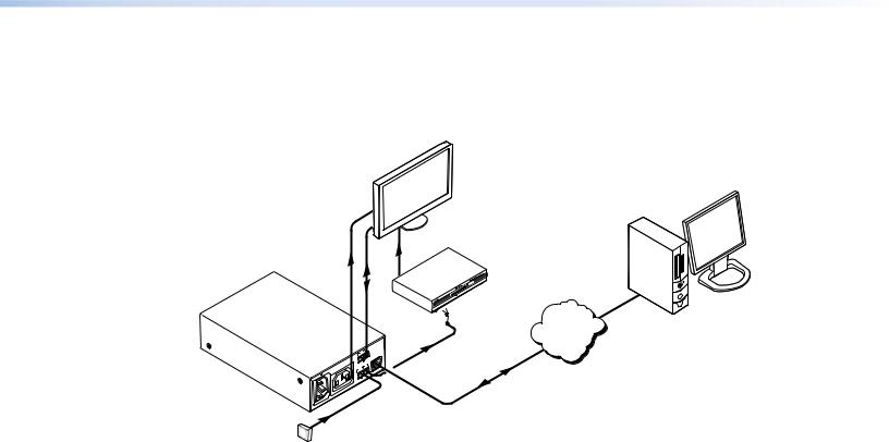
Application Diagram
The following application diagram shows an example of how devices can be connected to the IPL T PC1 or the IPL T PC1i.
Extron
IPL T PC1i
Ethernet Control
Interface
AC Power
RS-232
|
|
|
COM |
|
|
|
|
+5V |
LAN |
|
|
|
|
|
|
|
|
TX RX |
|
|
|
|
IR |
|
|
|
z |
INPUT |
|
|
|
50/60H |
G |
|
|
-240V |
|
S |
|
200 |
|
IN |
|
|
|
|
|
MAX |
|
|
|
|
10A |
|
|
|
|
OUTPUT |
|
|
|
|
POWER |
|
|
MA |
X |
|
|
|
10A |
|
|
|
 ON
ON 
Plasma |
Remote User |
Control and |
|
Display |
Administrator |
|
Monitoring |
DVD |
|
Extron |
|
IR Emitter |
TCP/IP |
|
|
|
Network |
Ethernet |
|
Kiosk
Button
Figure 1. Connection Diagram for an IPL T PC1
IPL T PC1 • Introduction |
3 |

Installation and
Rear Panel
This section describes:
•Installation Overview
•Rear Panels
•Connecting Cables
Installation Overview
To install and set up an IPL T PC1 interface:
1.Disconnect power from the PC1 interface and the output device (plasma display, VCR, projector, and so forth).
2.If desired, mount the PC1 interface (see “Mounting the IPL T PC1 Interface”).
3.Plug the PC1 power cord into an AC wall outlet.
4.Connect a LAN Ethernet cable from your computer to the RJ-45 port on the PC1 rear panel to establish a link to the network (see “Wiring the Local Area Network [LAN] Port”).
5.Set up an IP address for the PC1 (see “HTML Configuration and Control” or “SIS Programming and Control”).
6.Plug an output device into the output power receptacle on the PC1 rear panel.
7.If desired, connect the output device to the serial COM port.
8.If desired, connect a contact closure device to the Input port.
9.If desired, connect an IR emitter to the IR port.
10.Press the front panel button to power on the receptacle.
11.Power on the output device.
12.Configure the PC1 interface using Global Configurator (provided on the included software DVD) or the embedded web pages.
IPL T PC1 • Installation and Rear Panels |
4 |
Rear Panels
1 |
|
2 |
3 |
100-120VAC |
50/60Hz |
MAC ADDRESS |
|
|
|
|
COM |
|
T |
|
|
DIO/VIDEO |
|
|
APARATUS |
TX RX |
+5V |
LAN |
INPUT |
IR |
4 |
|
|
12A MAX |
POWER OUTPUT 12A MAX |
IN |
S G |
|
|
||
|
7 |
6 |
5 |
Figure 2. IPL T PC1 Rear Panel (120 VAC)
1 |
|
2 |
3 |
200-240VAC |
50/60Hz |
MAC ADDRESS |
|
|
|
|
COM |
|
|
TX RX |
+5V |
LAN |
INPUT |
IR |
4 |
|
|
10A MAX |
POWER OUTPUT 10A MAX |
IN |
S G |
|
|
7 6 5
Figure 3. IPL T PC1i Rear Panel (220 VAC)
APower connector — Connect a power cord from a wall outlet to this male IEC power receptacle.
BUID label — Contains the unique User ID number (MAC address) of the unit (for example, 00-05-A6-00-00-01).
CCOM port (RS-232) — Connect the output device serial port to this captive screw connector to enable bidirectional RS-232 device control. This serial port contains the
following four pins, in order from left to right on the rear panel: transmission (Tx), receiving (Rx), ground (_), and +5 V (to tie hand-shaking lines on the controlled device if needed).
DLAN connector and LEDs — An Ethernet connection can be used on an ongoing basis to monitor and control the PC1 and the device connected to it (see “Wiring the Local Area Network (LAN) Port” for instructions on connecting the host to this port).
•RJ-45 port — Plug a patch cable into this RJ 45 female socket, and connect the other end to a network switch, hub, router, or computer.
•Link LED — This green LED lights to indicate a good network connection.
•Activity LED — This yellow LED blinks to indicate network activity.
LAN
RJ-45
Port


 Link
Link
LED
Activity
LED
IPL T PC1 • Installation and Rear Panels |
5 |

EIR port — Connect an IR emitter to pins 3 (S, for signal) and 4 (G, for ground) of this shared captive screw connector to enable infrared remote control of the output device (see “Wiring for IR Control” for instructions on connecting an IR emitter to this port).
The PC1 provides enough current to power one IR emitter up to 4000 feet, or a maximum of four emitters in parallel up to 100 feet each. To enable IR control, load an
Extron IR driver to the PC1 for the output device, using Global Configurator, the PC1 web pages, or IR Learning.
FInput contact closure port — Connect a contact closure device to pins 1 (IN, for input) and 2 (_, for ground) of this shared captive screw connector to enable the PC1 to detect a closed circuit between an input and ground and to trigger an event (see “Wiring the Contact Input Port”).
For example, if a button were pressed or motion were detected by a sensor, the input would short to ground, which would cause an event such as a bell ringing, a light turning on, or an e-mail notification that an event has occurred.
GOutput power receptacle — Connect the power cord from an output device to this female 3-prong Edison (IPL T PC1) or IEC (IPL T PC1i) power output receptacle.
Connecting Cables
Connect cables to the rear panel connectors as outlined below.
1.Plug an IEC power cord into a wall outlet and into the 3-prong male power connector on the PC1 rear panel. The green Power LED lights and remain lit.
2.Plug the Ethernet cable from the network into the LAN port on the rear panel. The green Link LED on the connector lights.
3.Plug the power cord of the output device to be controlled into the output receptacle on the PCI rear panel.
4.If desired, connect the output device to the RS-232 COM port.
5.If desired, connect an IR emitter to the IR port to control an output device.
6.If desired, connect a contact switch to the contact input port.
The following sections provide details on wiring the appropriate cables to the rear panel connectors.
RS-232 Port Cabling
To connect an output device, such as a plasma display or projector, to the PC1 RS-232 connector, see the “Extron IP Link Device Interface Communication Sheet” for your display device. This sheet contains information about your device, including connector pin assignments and connection diagrams, and is available from the Extron website.
Accessing the Communication Sheet
To obtain the Communication Sheet for your output device:
1.On the Extron website (www.extron.com), click the Download tab.
2.On the Download Center page, click the Device Drivers button (shown at right).
3.At the bottom of the Device Drivers page, select IPL T PC1 from the drop-down menu.
4.On the next web page, select Serial from the Protocol Type drop-down menu to display a list of the Extron serial drivers.
IPL T PC1 • Installation and Rear Panels |
6 |
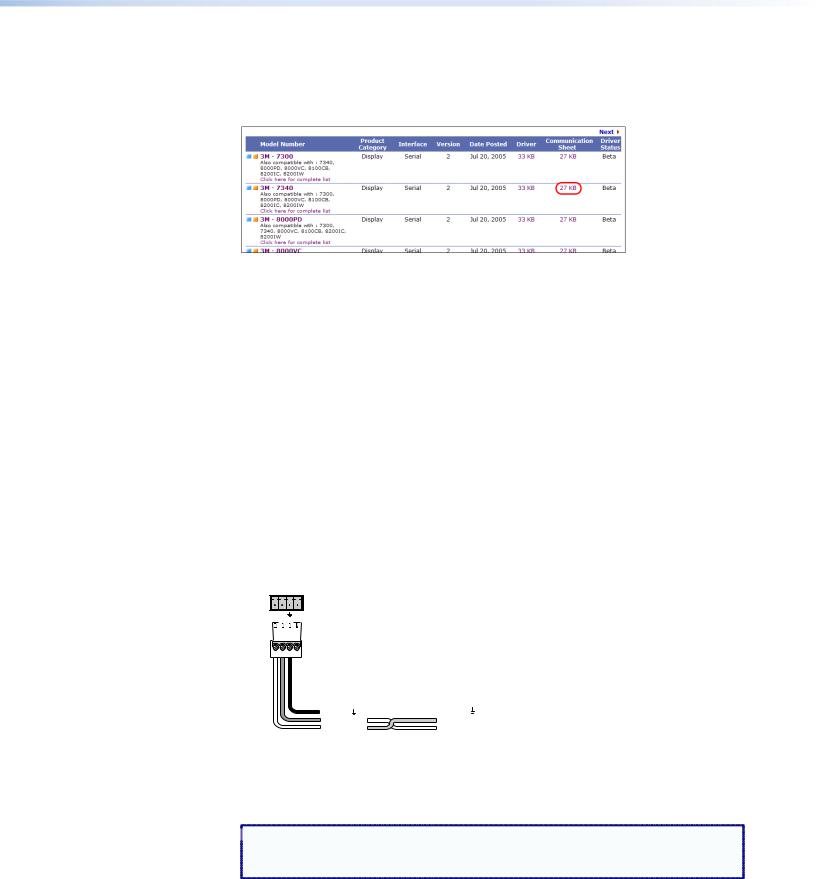
5.On the drivers list, locate the model name of your output device. In the row for your device, click on the nnKb link in the Communication Sheet column.
In figure 4, below, the Communication sheet link for a 3M-7340 display has been selected.
Figure 4. Communication Sheet Access
6.The communication sheet (a PDF file) opens. You can view, print, or download it.
7.Wire your display device as described in its communication sheet.
You can also access the Communication Sheets via the Global Configurator software (see the IPL T PC1 Setup Guide for information on using GC3.2).
Connecting the Display Device
To connect the display device to the PC1:
1.Wire an RS-232 cable to the provided 4-pole captive screw connector, as described below. Use only the first three pins of the connector, starting from the left.
a.Connect the wire from the Receive port of the display to the first pin (on the left) of the connector, which plugs into the PC1 Tx (Transmit) port.
b.Connect the wire from the Transmit port of the display to the second pin of the connector, which plugs into the PC1 Rx (Receive) port.
c.Connect the ground wire from the display to the third pin of the connector, which plugs into the PC1 ground (_) port.
RS-232
Tx Rx |
+5V |
IPL T PC1
Rear Panel
RS-232 Port
|
|
|
|
|
|
|
|
|
|
|
|
|
|
|
|
|
|
|
|
|
|
|
|
|
|
|
|
|
|
|
|
|
|
|
|
|
|
|
|
|
Ground ( |
|
) |
|
Ground ( |
|
) |
|
|
|
|
|
|
|
|
|
Receive (Rx) |
|
Receive (Rx) |
||||
|
|
|
|
|
|
|
|
|
Transmit (Tx) |
|
Transmit (Tx) |
||||
|
|
|
|
|
|
|
|
|
|
|
|
Bidirectional |
|
|
|
|
|
|
|
|
|
|
|
|
|
|
|
Display |
|||
|
|
|
|
|
|
|
|
|
|
|
|
|
|||
|
|
|
|
|
|
|
|
|
|
|
|
|
Device |
||
Figure 5. Connecting an Output Device to the RS-232 Port
2. Plug the cable into the RS-232 receptacle on the PC1 rear panel.
 NOTE: The RS-232 port is by default a control port. If you want to use it to
configure the PC1, you must perform a mode 2 reset (see “Resetting” in the “Front Panel Features and Operation” section).
IPL T PC1 • Installation and Rear Panels |
7 |
Wiring the Local Area Network (LAN) Port
Wire the connector as shown in the tables below.
•For 10Base-T (10 Mbps) networks, use a Category 3 or better cable.
•For 100Base-T (100 Mbps) networks, use a Category 5 cable.
•Use a straight-through cable to connect to a switch, hub, or router.
•Use a crossover cable to connect directly to a computer.
Pins:
12345678
Insert Twisted
Pair Wires
RJ-45
Connector
Figure 6.
Crossover Cable
|
End 1 |
End 2 |
Pin |
Wire Color |
Wire Color |
|
|
|
1 |
White-orange |
White-green |
|
|
|
2 |
Orange |
Green |
|
|
|
3 |
White-green |
White-orange |
|
|
|
4 |
Blue |
Blue |
|
|
|
5 |
White-blue |
White-blue |
|
|
|
6 |
Green |
Orange |
|
|
|
7 |
White-brown |
White-brown |
|
|
|
8 |
Brown |
Brown |
|
|
|
|
T568A |
T568B |
A cable that is wired as T568A at one end and T568B at the other (Tx and Rx pairs reversed) is a "crossover" cable.
RJ-45 Connector Wiring
Straight-through Cable
Pin |
End 1 |
End 2 |
Wire Color |
Wire Color |
|
|
|
|
1 |
White-orange |
White-orange |
|
|
|
2 |
Orange |
Orange |
|
|
|
3 |
White-green |
White-green |
|
|
|
4 |
Blue |
Blue |
|
|
|
5 |
White-blue |
White-blue |
|
|
|
6 |
Green |
Green |
|
|
|
7 |
White-brown |
White-brown |
|
|
|
8 |
Brown |
Brown |
|
|
|
|
T568B |
T568B |
A cable that is wired the same at both ends is called a "straight-through" cable, because no pin or pair assignments are swapped.
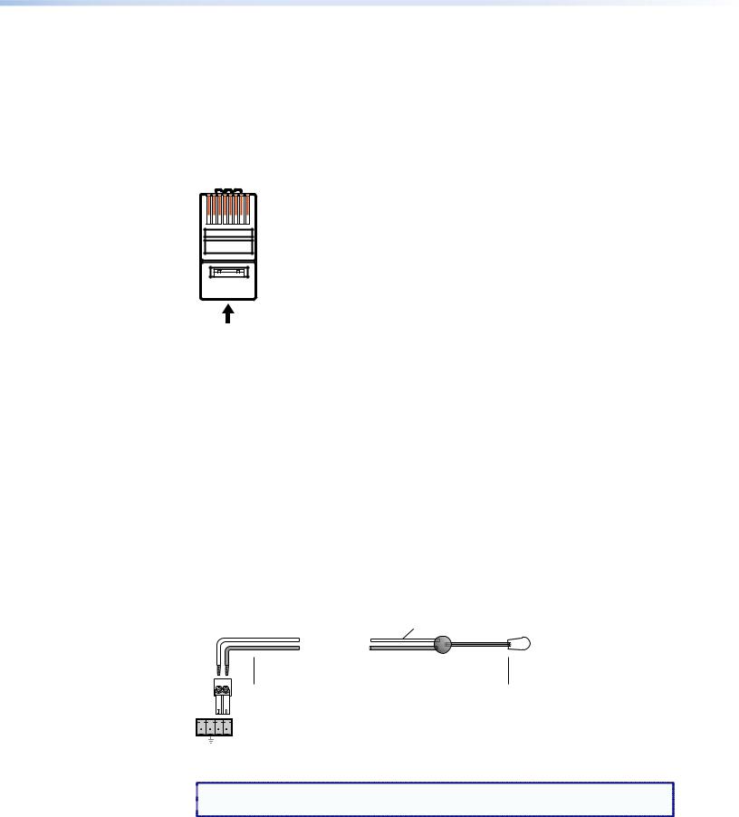
Wiring for IR Control
If you intend to control the display device via infrared (IR) commands from the PC1, wire an Extron IR emitter to a 3.5 mm, 2-pole captive screw connector (provided), and plug the 2-pole connector into the IR Signal and Ground pins (pins 3 and 4) of the shared captive screw connector on the rear panel.
Alternatively, you can wire the IR emitter to pins 3 and 4 of the provided 4-pole captive screw plug (and, if desired, also wire a contact closure device to pins 1 and 2 of the same 4-pole connector; see “Wiring the Contact Input Port” on the next page). Plug the wired 4-pole connector into the rear panel Input/IR connector.
The PC1 provides enough current to power one IR Emitter up to 4000 feet, or up to four emitters for 100 feet each (see figure 7, below).
White Striped Wire Only |
IR |
|
Emitter |
||
|
E Modulated IR
D Ground
 4000 feet (1574.8 m) Maximum
The PC1 can power a single IR Emitter up to 4000 feet, or four emitters wired in parallel up to 100 feet each.
|
IPL T PC1 Shared IR |
|
and Input Connector |
In |
S G |
Figure 7. Wiring for IR Control via an IR Emitter
 NOTE: Place the head of the IR emitter over or directly adjacent to the IR receiver of the
  controlled device.
IPL T PC1 • Installation and Rear Panels |
8 |

Wiring the Contact Input Port
The IPL T PC1 contact closure Input port can be connected to any device providing a closure to ground (closed = logic 1 and open = logic 0). The contact input is connected to 5 VDC via a 1k ohm pull-up resistor and must be wired with a ground. This allows the input to be tied to a device such as a motion detector, alarm, photo eye, and so forth. You can define what this input will trigger via GC3.3.
1.Connect one end of the input cable to a 3.5 mm, 2-pole captive screw connector (provided), and plug the connector into the two Input pins (In and _ ) of the shared Input/IR port connector on the rear panel.
Alternatively, you can wire the contact closure device to pins 1 and 2 (from the left) of the provided 4-pole captive screw plug (and, if desired, also wire an IR emitter to pins 3 and 4 of the same 4-pole connector; see “Wiring for IR Control” on the previous page). Plug the wired 4-pole connector into the rear panel Input/IR connector.
2.Connect the other end of the input cable to the contact input device that will provide a triggering signal (see the diagram at right).
INPUT IR
IN |
S |
G |
Momentary
Switch
IPL T PC1 • Installation and Rear Panels |
9 |
Front Panel
Features and
Operation
This section contains a description of the IPL T PC1 and IPL T PC1i front panel features and instructions for setting up the PC1 using the front panel. The following topics are discussed:
•Front Panel Features
•Setting Up the System Using the Front Panel
•Resetting
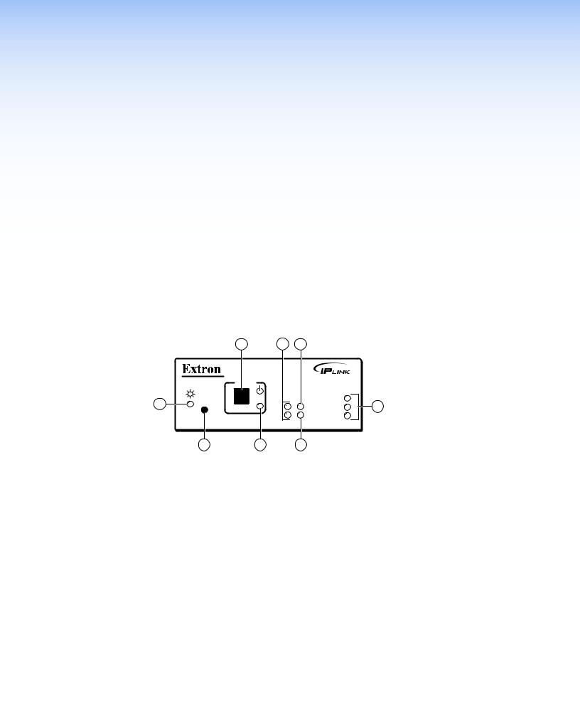
Front Panel Features
|
|
1 |
2 |
3 |
|
|
|
IPL T PC1 |
POWER |
|
|
|
|
8 |
R |
|
|
|
100 |
|
|
TX |
INPUT |
LINK |
4 |
||
|
|
|||||
|
|
|
RX |
IR |
ACT |
|
|
7 |
|
6 |
5 |
|
|
Figure 8. IPL T PC1 and IPL T PC1i Front Panel
APower button — Press this button to switch power on and off to the output receptacle on the rear panel.
BTx and Rx LEDs — The Tx (transmit) LED lights when RS-232 data is being transmitted. The Rx LED lights when RS-232 data is being received.
CInput LED — This green LED lights when the Input contact closure port is activated
(shorted).
DLAN status LEDs — These three LEDs show the status of the Ethernet connection as follows:
•100 — When lit, indicates a 100 Mbs connection speed. Otherwise, the connection speed is 10 Mbs.
•Link — Lights steadily while the interface has an active network connection.
•Act (Activity) — Blinks while data is being sent or received.
EIR LED — This green LED lights when IR data is being transmitted.
FReceptacle power LED — This red LED lights while power is being supplied to the rear panel receptacle and, therefore, to the attached output device.
IPL T PC1 • Front Panel Features and Operation 10
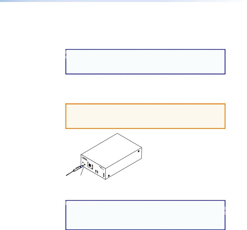
GReset button (recessed) — Use the tip of a small Phillips screwdriver or an Extron
Tweeker (provided) to press this recessed button to reset the unit in one of five reset modes (see “Resetting,” later in this section, for details on reset modes and on using this Reset button).
HPower LED — This green LED lights while the PC1 or PC1i interface is receiving power and is running.
When the unit is being reset from the front panel, this LED blinks the appropriate number of times to indicate the reset mode the PC1 has entered (see “Resetting”).
Setting Up the System Using the Front Panel
The following system setup procedures can be performed using the front panel, Global
Configurator, the embedded web pages, or SIS commands.
This section discusses the front panel procedures. For information on using the web to set up, see “HTML Configuration and Control.” For the equivalent SIS commands, see “SIS Programming and Control.” For information on setting up using Global Configurator, see the IPL T PC1 Setup Guide.
 NOTE: The PC1 takes approximately 2 minutes to store settings made via the front
panel, SIS commands, or the web pages into its memory. If you disconnect
power from the PC1 less than 2 minutes after entering a setting, your entry may be lost.
Setting Up Power Control of the Output Device
To set up power control of the output device plugged into the PC1 output power receptacle:
1.On the PC1 front panel, press and release the receptacle Power button.
The green receptacle Power LED at the right of the button lights and remains lit while the receptacle is powered on. It turns off when the receptacle is powered off.
2.Power on the device, using its own power switch.
POWER
Receptacle |
I |
|
|
Power Button |
|
|
Receptacle |
|
Power LED |
If power is removed from the PC1, the power state of the output receptacle is preserved in flash memory; for example, if the receptacle was powered on when the PC1 was disconnected, it is powered on when the PC1 receives power again. This enables the receptacle configuration to be easily restored if a power loss occurs.
 CAUTION: Some devices, such as projectors, need a cool-down period to power off safely. Use RS-232 or IR commands to power these devices.
IPL T PC1 • Front Panel Features and Operation 11
Front Panel Security Lockout (Executive Mode)
When the PC1 is in front panel lock mode (executive mode), it does not accept commands from the front panel. If any button is pressed while the unit is in executive mode, the Power
LED flashes three times, indicating that the input from the front panel is not being accepted.
To enter or exit executive mode, press and hold the receptacle Power button for 3 seconds.
The Power LED flashes three times to indicate that the executive mode has been switched.
 NOTES: • If power to the PC1 is recycled while the unit is in executive mode, the PC1
  remains in executive mode.
• The Reset button is always functional. It is recessed to avoid it being pressed accidentally.
Resetting
Reset the unit by pressing the Reset button on the front panel. This button is recessed, and can be accessed with an Extron Tweeker or other small Phillips screwdriver.
CAUTIONS: • Review the reset modes carefully. Use of the wrong reset mode may cause unintended loss of flash memory programming or a unit reboot.
•The reset modes described on the following pages break all TCP/IP connections by closing all sockets to the unit.
 IPLT
IPLT  PC1
PC1
R
POW
I
TX |
|
|
RX |
INPUT |
|
|
100 |
|
|
IR |
|
|
|
LINK |
|
|
ACT |
Recessed Reset Button Use tip of Philips head on Tweeker to activate.
Figure 9. Reset Button
 NOTES: • If the Reset button is continually held in, the Power LED pulses (blinks) every
3 seconds, and with each pulse, the PC1 goes into a different reset mode. For  mode 5, the LED blinks three times, indicating that it is the last mode.
• The reset modes are separate functions, not a progression from mode 1 to mode 5.
IPL T PC1 • Front Panel Features and Operation 12

Mode 1
Activation |
Hold in the Reset button while applying power to the unit. |
|
|
Result |
Returns the unit to the default base firmware that was shipped |
|
with the PC1 from the factory. Event scripting does not start when |
|
the unit is powered on in this mode. |
|
|
Purpose and notes |
Use mode 1 to remove a version of firmware if incompatibility |
|
issues arise. All user files and settings are maintained. User web |
|
pages may not work correctly if you are using an earlier firmware |
|
version. |
 NOTE: After a mode 1 reset, the factory-installed firmware version remains in effect
only until the unit is powered off. After a power cycle, the PC1 returns to the firmware that was installed prior to the mode 1 reset.
Mode 2
Activation |
To enter mode 2, you use both the PC1 front panel and your |
|
computer, as follows: |
|
1. On the computer, open a command interface, such as Extron |
|
DataViewer or HyperTerminal. |
|
2. Immediately press the Reset button momentarily (for less than |
|
1 second). |
|
NOTE: Nothing happens if the momentary press does |
|
not occur within 1 second. |
|
3. Within 2 seconds of the momentary press, press the <+> |
|
key on the computer keyboard three times. |
Result |
The RS-232 port is converted to a host port, which allows the use |
|
of SIS commands and host responses. |
|
No LEDs blink to indicate the mode switch. If the switch to mode 2 |
|
is successful and serial port communication is enabled, the interface |
|
screen displays one of the following copyright messages: |
•(c) Copyright 2011, Extron Electronics, IPL T PC1, Vn.nn, 60-544-nn
•(c) Copyright 2011, Extron Electronics, IPL T PC1i, Vn.nn, 60-544-nn
Purpose and notes By default, the RS-232 port is a device control port. In mode 2, the serial port is able to receive SIS commands.
 NOTE: If you do not enter the three plus (+) signs within 2
seconds of the momentary press of the Reset button, the RS-232 port reverts to a device control port.
IPL T PC1 • Front Panel Features and Operation 13

Mode 3
Activation |
Hold the Reset button in until the Power LED blinks once |
|
(approximately 3 seconds). Release it, then immediately press it |
|
again momentarily (for less than 1 second). |
|
NOTE: Nothing happens if the momentary press does not |
|
occur within 1 second. |
Result |
Turns events on or off, depending on their current state. During |
|
resetting, the reset LED flashes two times if events are starting and |
|
three times if events are stopping. |
Purpose and notes This mode is used for troubleshooting.
Mode 4
Activation |
Hold the Reset button in until the Power LED blinks twice |
|
(approximately 6 seconds). Release it, then immediately press it |
|
again momentarily (for less than 1 second). The Power LED blinks |
|
four times in quick succession, confirming a mode 4 reset. |
|
NOTE: Nothing happens if the momentary press does not |
|
occur within 1 second. |
Result: Reset mode 4 does the following:
•Enables ARP program capability.
•Sets the IP address back to factory IP settings.
•Sets the subnet mask back to factory default.
•Sets the gateway address back to factory default.
•Sets port mapping back to factory default.
•Turns DHCP off.
•Turns events off.
Purpose and notes Mode 4 enables you to set IP address information using ARP and the MAC address.
Mode 5
Activation: Hold in the Reset button until the Power LED blinks three times
(approximately 9 seconds). Release it, then immediately press it again momentarily (for less than 1 second). The power LED blinks four times in quick succession, confirming a mode 5 reset.
 NOTE: Nothing happens if the momentary press does not occur
 within 1 second.
Result: Performs a complete reset to factory defaults (except for the firmware).
Purpose and notes Mode 5 is useful if you want to start over with control software configuration and to replace events.
IPL T PC1 • Front Panel Features and Operation 14
HTML
Configuration
and Control
This section describes the IPL T PC1 embedded web pages and provides instructions on accessing and using them to configure the PC1. Topics include:
•Configuring the Hardware for Ethernet Control
•Using the IPL T PC1 Web Pages
•Custom Web Pages
•Troubleshooting
•Global Configurator Software
The IPL T PC1 must be configured before use in order for it to control other devices. In addition to using the button on the PC1 front panel, you can configure and control the PC1 via any computer attached to a LAN.
•The default PC1 embedded web pages provide a means of setting up, adjusting, and controlling the interface via a web browser from any type of network-enabled computer.
•An alternative way to control and configure the PC1 from your computer is by using Simple Instruction Set (SIS) commands via Telnet. SIS commands are discussed in detail in the “SIS Programming and Control” section.
•Global Configurator (GC 3.3) software enables you to configure and control the PC1 as well as set up output device monitoring and scheduling (see the IPL T PC1 Setup Guide, provided with your PC1, for information on setting up using GC 3.3).
Configuring the Hardware for Ethernet Control
To enable Ethernet control, both the computer and the PC1 must be configured correctly.
The PC must be network-capable with the proper protocols, and the PC1 must be set up so it can be connected to a LAN (local area network). Please note that some settings can be configured only via Internet protocol.
For your PC to communicate with the PC1 via Ethernet, it must be equipped with an network interface card and an HTML browser. To allow your PC to work with Extron Ethernet-controlled products, the TCP/IP protocol must be installed and properly configured.
IPL T PC1 • HTML Configuration and Control 15
Setting Up and Configuring the PC1 Using ARP
The Address Resolution Protocol (ARP) command provides a quick way to set up an IP address for the PC1, using your PC. The ARP commands tell your computer to associate the PC1 Media Access Control (MAC) address with an IP address that you assign.
1.Obtain a valid IP address for your PC1 from your network administrator.
2.Obtain the PC1 MAC address (UID#) from the small label on the PC1 rear panel (see
“Rear Panels” in the “Installation and Rear Panels” section). The MAC address should have the following format:
00-05-A6-nn-nn-nn
3.If the PC1 has never been configured and is still set for factory defaults, skip to step 4. If not, perform a mode 4 system reset to restore the factory-set values (see “Resetting” in the “Front Panel Features and Operations” section for the resetting procedure.)
CAUTION: The PC1 must be configured with the factory default IP address (192.168.254.254) before you execute the ARP command, as described below.
4.On the computer, access the command prompt as follows:
a.From your Windows desktop Start menu, select Run... .
b.On the Run window, enter cmd. The command window opens.
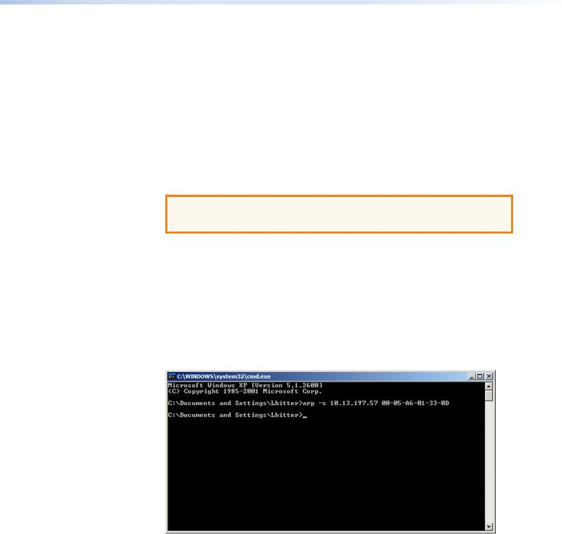
5.At the command prompt enter arp -s, followed by the desired new IP address for the PC1, a space, and finally the PC1 MAC address (taken from the small label on the rear panel; see “Rear Panels” in the “Installation and Rear Panels” section).
For example:
arp -s 10.13.197.57 00-05-A6-01-33-0D
A space must separate arp and the hyphen [-].
Figure 10. ARP-S Command Screen
6.Execute a ping command by entering ping, followed by the new IP address, at the command prompt. For example:
ping 10.13.197.57
Ping is a utility or diagnostic tool that tests network connections. It is used to determine if the host has an operating connection and is able to exchange information with another host.
IPL T PC1 • HTML Configuration and Control 16
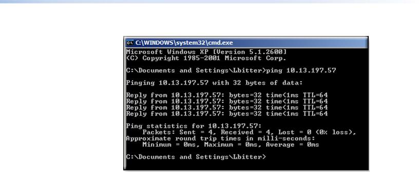
The response should be the new IP address of the PC1, as shown below.
Figure 11. Ping Command on a Command Prompt Screen
7.After verifying that the IP address change was successful, issue the arp -d command at the DOS prompt to remove the address from the computer ARP table.
For example:
arp -d 10.13.197.57
A space must separate arp from the hyphen (-).
Setting Up and Configuring the PC1 Using a Web Browser
To set up the PC1 for Ethernet communication using a web browser, you must temporarily configure the PC to communicate with the interface. Then you can change the default settings of the PC1 (IP address, subnet mask, and [optionally] administrator name and password) in order to use the unit on an intranet (LAN) or on the Internet (WAN). After you have set up the PC1 for network communication, you can reset the computer to its original network configuration.
IPL T PC1 LAN port defaults
PC1 IP address: |
192.168.254.254 |
Gateway IP address: |
0.0.0.0 |
Subnet mask: |
255.255.0.0 |
DHCP: |
Off |
Link speed and duplex level: |
Auto detected |
If you use an existing Ethernet LAN intranet, your network administrator can provide you with a unique IP address for the PC1 or confirm whether you need to set up the PC1 for
DHCP (Dynamic Host Configuration protocol) to have an address assigned automatically.
IPL T PC1 • HTML Configuration and Control 17
Setting Up the Computer for IP Communication
Follow these steps to set up communication between your computer and the PC1 using
Windows 2000, Windows XP, or Windows 7.
 NOTE: The procedure and illustrations in this section are for Windows XP. For other
  Windows versions, the screens may appear slightly different.
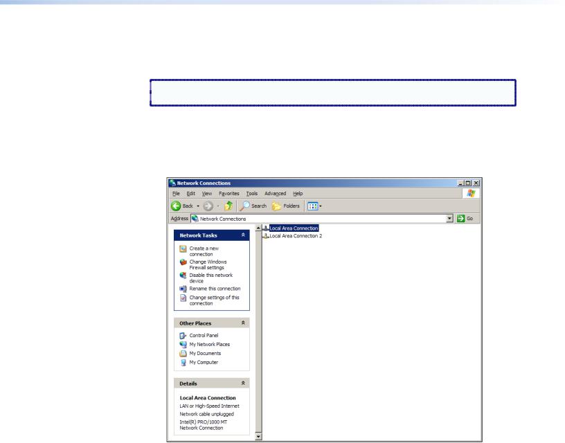
1.Open the Network Connections page as follows:
a.From the Start menu, select My Network Places.
b.From the Network Tasks side-bar menu, select View Network connections.
2.Right-click Local Area Connection, then select Properties.
Figure 12. Network Connections Window
IPL T PC1 • HTML Configuration and Control 18
Loading...