Extron electronic MTP 1500RL User Manual

MTP 1500RL 15HD A SEQ • Setup Guide
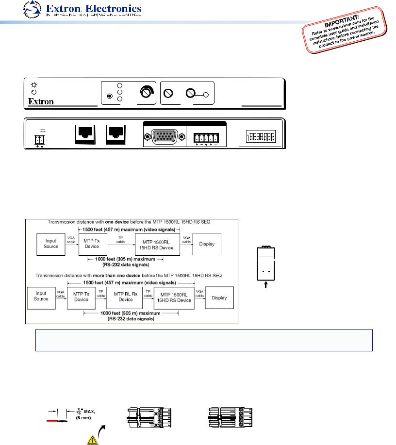
This guide provides basic instructions for an experienced installer to set up and operate the Extron MTP 1500RL 15HD A SEQ twisted pair receiver.
For full details, see the MTP 1500RL 15HD A SEQ User Guide, available online at www.extron.com.
RED |
|
LEVEL PEAKING |
|
SELECT GREEN |
|
|
|
BLUE |
ADJUST |
|
MIN/MAX |
DELAY |
RGB |
MTP 1500RL Series |
INPUT |
BUFFERED OUTPUT |
OUTPUT |
|
POWER |
|
MONO |
AUDIO |
12V |
|
L |
R |
1.0A MAX |
|
|
|
MTP |
MTP |
|
|
SPARE
END
VIDEO
SOG
CSYNC
V +
H +
ON |
MTP 1500RL 15HD A SEQ |
Installation and Setup
Step 1 — Mounting
Turn off or disconnect all equipment power sources. Mount the MTP 1500RL 15HD A SEQ receiver as required.
Step 2 — Connect Input
Connect the RJ-45 cable from an MTP transmitter to the Input port on the MTP 1500RL 15HD A SEQ receiver. Terminate the cable as shown below right, using the same standard (A or B) at both ends.
|
|
|
|
|
|
Pin |
T568A Wire |
T568B Wire |
|
|
|
|
|
|
|
Color |
Color |
RJ-45 Connector |
|
|
|
|||||
|
|
|
||||||
1 |
White-green |
White-orange |
||||||
|
|
Pins: |
|
|
|
|||
12345678 |
|
|
2 |
Green |
Orange |
|||
|
|
|
|
|
|
|||
|
|
|
|
|
|
3 |
White-orange |
White-green |
|
|
|
|
|
|
|||
|
|
|
|
|
|
|||
|
|
|
|
|
|
4 |
Blue |
Blue |
|
|
|
|
|
|
|
|
|
|
|
|
|
|
|
5 |
White-blue |
White-blue |
|
|
|
|
|
|
|||
|
|
|
|
|
|
|
|
|
|
|
|
|
|
|
6 |
Orange |
Green |
|
|
|
|
|||||
Insert Twisted |
7 |
White-brown |
White-brown |
|||||
|
Pair Wires |
|
|
|
||||
|
8 |
Brown |
Brown |
|||||
|
|
|
|
|
|
|||
|
|
|
|
|
|
|
|
|
NOTE: The transmitter and receiver are designed for and perform best with Extron Enhanced Skew-Free AV cable terminated in accordance with the TIA/EIA T568A standard. CAT 5 cables are acceptable but less preferable. Using preterminated and tested cables is also recommend, Cables terminated on site should be tested before use to ensure that they comply with Category 5 specifications.
Step 3 — Connect Outputs
Attach the applicable output cables (video, audio, and buffered output).
A.High resolution video output — Connect a display device to the 15-pin HD connector (RGB).
B.Audio connector — Connect an audio device to the 5-pole captive screw connector for mono audio output
|
Mono output 1 |
|
NO GROUND. |
|
Sleeve(s) |
Do not tin the wires! |
Mono output 2 |
NO GROUND. |
Unbalanced Output
MONO 1 |
Mono output 1+ |
MONO 1 |
Mono output 1- |
||
AUDIO 2 |
Sleeve(s) |
AUDIO 2 |
Mono output 2+ |
||
|
Mono output 2- |
|
Balanced Output
CAUTION
For unbalanced audio, connect the sleeve(s) to the ground contact.
DO NOT connect the sleeves to the negative (-) contacts.
C.Buffered output — Connect up to 5 daisy-chained MTP receivers to this RJ-45 connector.
 Loading...