


 Loading...
User Guide
IP Link®
IPL T PCS4
IPL T PCS4i
IP Link Power Control Interfaces
68-738-07 Rev. B
09 11

Safety Instructions • English
This symbol is intended to alert the user of important operating and maintenance (servicing) instructions in the literature provided with the equipment.
This symbol is intended to alert the user of the presence of uninsulated dangerous voltage within the product’s enclosure that may present a risk of electric shock.
Caution
Read Instructions • Read and understand all safety and operating instructions before using the equipment. Retain Instructions • The safety instructions should be kept for future reference.
Follow Warnings • Follow all warnings and instructions marked on the equipment or in the user information.
Avoid Attachments • Do not use tools or attachments that are not recommended by the equipment manufacturer because they may be hazardous.
Warning
Power sources • This equipment should be operated only from the power source indicated on the product. This equipment is intended to be used with a main power system with a grounded (neutral) conductor. The third (grounding) pin is a safety feature, do not attempt to bypass or disable it.
Power disconnection • To remove power from the equipment safely, remove all power cords from the rear of the equipment, or the desktop power module (if detachable), or from the power source receptacle (wall plug).
Power cord protection • Power cords should be routed so that they are not likely to be stepped on or pinched by items placed upon or against them.
Servicing • Refer all servicing to qualified service personnel. There are no user-serviceable parts inside. To prevent the risk of shock, do not attempt to service this equipment yourself because opening or removing covers may expose you to dangerous voltage or other hazards.
Slots and openings • If the equipment has slots or holes in the enclosure, these are provided to prevent overheating of sensitive components inside. These openings must never be blocked by other objects.
Lithium battery • There is a danger of explosion if battery is incorrectly replaced. Replace it only with the same or equivalent type recommended by the manufacturer. Dispose of used batteries according to the manufacturer instructions.
Consignes de Sécurité • Français
Ce symbole sert à avertir l’utilisateur que la documentation fournie avec le matériel contient des instructions importantes concernant l’exploitation et la maintenance (réparation).
Ce symbole sert à avertir l’utilisateur de la présence dans le boîtier de l’appareil de tensions dangereuses non isolées posant des risques d’électrocution.
Attention
Lire les instructions• Prendre connaissance de toutes les consignes de sécurité et d’exploitation avant d’utiliser le matériel.
Conserver les instructions• Ranger les consignes de sécurité afin de pouvoir les consulter à l’avenir.
Respecter les avertissements • Observer tous les avertissements et consignes marqués sur le matériel ou présentés dans la documentation utilisateur.
Eviter les pièces de fixation • Ne pas utiliser de pièces de fixation ni d’outils non recommandés par le fabricant du matériel car cela risquerait de poser certains dangers.
Avertissement
Alimentations • Ne faire fonctionner ce matériel qu’avec la source d’alimentation indiquée sur l’appareil. Ce matériel doit être utilisé avec une alimentation principale comportant un fil de terre (neutre). Le troisième contact (de mise à la terre) constitue un dispositif de sécurité : n’essayez pas de la contourner ni de la désactiver.
Déconnexion de l’alimentation• Pour mettre le matériel hors tension sans danger, déconnectez tous les cordons d’alimentation de l’arrière de l’appareil ou du module d’alimentation de bureau (s’il est amovible) ou encore de la prise secteur.
Protection du cordon d’alimentation • Acheminer les cordons d’alimentation de manière à ce que personne ne risque de marcher dessus et à ce qu’ils ne soient pas écrasés ou pincés par des objets.
Réparation-maintenance • Faire exécuter toutes les interventions de réparation-maintenance par un technicien qualifié. Aucun des éléments internes ne peut être réparé par l’utilisateur. Afin d’éviter tout danger d’électrocution, l’utilisateur ne doit pas essayer de procéder lui-même à ces opérations car l’ouverture ou le retrait des couvercles risquent de l’exposer à de hautes tensions et autres dangers.
Fentes et orifices • Si le boîtier de l’appareil comporte des fentes ou des orifices, ceux-ci servent à empêcher les composants internes sensibles de surchauffer. Ces ouvertures ne doivent jamais être bloquées par des objets.
Lithium Batterie • Il a danger d’explosion s’ll y a remplacment incorrect de la batterie. Remplacer uniquement avec une batterie du meme type ou d’un ype equivalent recommande par le constructeur. Mettre au reut les batteries usagees conformement aux instructions du fabricant.
Sicherheitsanleitungen • Deutsch
Dieses Symbol soll dem Benutzer in der im Lieferumfang enthaltenen Dokumentation besonders wichtige Hinweise zur Bedienung und Wartung (Instandhaltung) geben.
Dieses Symbol soll den Benutzer darauf aufmerksam machen, daß im Inneren des Gehäuses dieses Produktes gefährliche Spannungen, die nicht isoliert sind und die einen elektrischen Schock verursachen können, herrschen.
Achtung
Lesen der Anleitungen • Bevor Sie das Gerät zum ersten Mal verwenden, sollten Sie alle Sicherheits-und Bedienungsanleitungen genau durchlesen und verstehen.
Aufbewahren der Anleitungen • Die Hinweise zur elektrischen Sicherheit des Produktes sollten Sie aufbewahren, damit Sie im Bedarfsfall darauf zurückgreifen können.
Befolgen der Warnhinweise • Befolgen Sie alle Warnhinweise und Anleitungen auf dem Gerät oder in der Benutzerdokumentation.
Keine Zusatzgeräte • Verwenden Sie keine Werkzeuge oder Zusatzgeräte, die nicht ausdrücklich vom Hersteller empfohlen wurden, da diese eine Gefahrenquelle darstellen können.
Vorsicht
Stromquellen • Dieses Gerät sollte nur über die auf dem Produkt angegebene Stromquelle betrieben werden. Dieses Gerät wurde für eine Verwendung mit einer Hauptstromleitung mit einem geerdeten (neutralen) Leiter konzipiert. Der dritte Kontakt ist für einen Erdanschluß, und stellt eine Sicherheitsfunktion dar. Diese sollte nicht umgangen oder außer Betrieb gesetzt werden.
Stromunterbrechung • Um das Gerät auf sichere Weise vom Netz zu trennen, sollten Sie alle Netzkabel aus der Rückseite des Gerätes, aus der externen Stomversorgung (falls dies möglich ist) oder aus der Wandsteckdose ziehen.
Schutz des Netzkabels • Netzkabel sollten stets so verlegt werden, daß sie nicht im Weg liegen und niemand darauf treten kann oder Objekte daraufoder unmittelbar dagegengestellt werden können.
Wartung • Alle Wartungsmaßnahmen sollten nur von qualifiziertem Servicepersonal durchgeführt werden. Die internen Komponenten des Gerätes sind wartungsfrei. Zur Vermeidung eines elektrischen Schocks
versuchen Sie in keinem Fall, dieses Gerät selbst öffnen, da beim Entfernen der Abdeckungen die Gefahr eines elektrischen Schlags und/oder andere Gefahren bestehen.
Schlitze und Öffnungen • Wenn das Gerät Schlitze oder Löcher im Gehäuse aufweist, dienen diese zur Vermeidung einer Überhitzung der empfindlichen Teile im Inneren. Diese Öffnungen dürfen niemals von anderen Objekten blockiert werden.
Litium-Batterie • Explosionsgefahr, falls die Batterie nicht richtig ersetzt wird. Ersetzen Sie verbrauchte Batterien nur durch den gleichen oder einen vergleichbaren Batterietyp, der auch vom Hersteller empfohlen wird. Entsorgen Sie verbrauchte Batterien bitte gemäß den Herstelleranweisungen.
Instrucciones de seguridad • Español
Este símbolo se utiliza para advertir al usuario sobre instrucciones
importantes de operación y mantenimiento (o cambio de partes) que se desean destacar en el contenido de la documentación suministrada con los equipos.
Este símbolo se utiliza para advertir al usuario sobre la presencia de elementos con voltaje peligroso sin protección aislante, que puedan encontrarse dentro de la caja o alojamiento del producto, y que puedan representar riesgo de electrocución.
Precaucion
Leer las instrucciones • Leer y analizar todas las instrucciones de operación y seguridad, antes de usar el equipo.
Conservar las instrucciones • Conservar las instrucciones de seguridad para futura consulta.
Obedecer las advertencias • Todas las advertencias e instrucciones marcadas en el equipo o en la documentación del usuario, deben ser obedecidas.
Evitar el uso de accesorios • No usar herramientas o accesorios que no sean especificamente recomendados por el fabricante, ya que podrian implicar riesgos.
•


••
••
Advertencia
Alimentación eléctrica • Este equipo debe conectarse únicamente a la fuente/tipo de alimentación eléctrica indicada en el mismo. La alimentación eléctrica de este equipo debe provenir de un sistema de distribución general con conductor neutro a tierra. La tercera pata (puesta a tierra) es una medida de seguridad, no puentearia ni eliminaria.
Desconexión de alimentación eléctrica • Para desconectar con seguridad la acometida de alimentación eléctrica al equipo, desenchufar todos los cables de alimentación en el panel trasero del equipo, o desenchufar el módulo de alimentación (si fuera independiente), o desenchufar el cable del receptáculo de la pared.
Protección del cables de alimentación • Los cables de alimentación eléctrica se deben instalar en lugares donde no sean pisados ni apretados por objetos que se puedan apoyar sobre ellos.
Reparaciones/mantenimiento • Solicitar siempre los servicios técnicos de personal calificado. En el interior no hay partes a las que el usuario deba acceder. Para evitar riesgo de electrocución, no intentar personalmente la reparación/mantenimiento de este equipo, ya que al abrir o extraer las tapas puede quedar expuesto a voltajes peligrosos u otros riesgos.
Ranuras y aberturas • Si el equipo posee ranuras o orificios en su caja/alojamiento, es para evitar el sobrecalientamiento de componentes internos sensibles. Estas aberturas nunca se deben obstruir con otros objetos.
Batería de litio • Existe riesgo de explosión si esta batería se coloca en la posición incorrecta. Cambiar esta batería únicamente con el mismo tipo (o su equivalente) recomendado por el fabricante. Desachar las baterías usadas siguiendo las instrucciones del fabricante.
•
•
•
•
•
•

FCC Class A Notice
This equipment has been tested and found to comply with the limits for a Class A digital device, pursuant to part 15 of the FCC Rules. Operation is subject to the following two conditions:
1.This device may not cause harmful interference.
2.This device must accept any interference received, including interference that may cause undesired operation.
The Class A limits are designed to provide reasonable protection against harmful interference when the equipment is operated in a commercial environment. This equipment generates, uses, and can radiate radio frequency energy and, if not installed and used in accordance with the instruction manual, may cause harmful interference to radio communications. Operation of this equipment in a residential area is likely to cause harmful interference, in which case the user will be required to correct the interference at his own expense.
 NOTE: This unit was tested with shielded cables on the peripheral devices. Shielded cables must be used with
the unit to ensure compliance with FCC emissions limits.
For more information on safety guidelines, regulatory compliances, EMI/EMF compliance, accessibility, and  related topics, click here.
iii
Conventions Used in this Guide
Notifications
In this user guide, the following are used:
 WARNING: A warning warns of things or actions that might cause injury, death, or
  other severe consequences.
 CAUTION: A caution indicates a potential hazard to equipment or data.
 NOTE: A note draws attention to important information.
 TIP: A tip provides a suggestion to make working with the application easier.
Software Commands
Commands are written in the fonts shown here:
^AR Merge Scene,,Op1 scene 1,1 ^B 51 ^W^C [01]R000400300004000080000600[02]35[17][03]
E X! *X1&* X2)* X2#* X2! CE}
 NOTE: For commands and examples of computer or device responses mentioned
in this guide, the character “0” is used for the number zero and “O” represents the capital letter “o.”
Computer responses and directory paths that do not have variables are written in the font shown here:
Reply from 208.132.180.48: bytes=32 times=2ms TTL=32 C:\Program Files\Extron
Variables are written in slanted form as shown here: ping xxx.xxx.xxx.xxx —t
SOH R Data STX Command ETB ETX
Selectable items, such as menu names, menu options, buttons, tabs, and field names are written in the font shown here:
From the File menu, select New. Click the OK button.
Copyright
© 2011 Extron Electronics. All rights reserved.
Trademarks
All trademarks mentioned in this guide are the properties of their respective owners.
iv

Contents
Introduction............................................................ |
1 |
About this Guide................................................. |
1 |
About the IPL T PCS4........................................... |
1 |
Features.............................................................. |
1 |
Application Diagrams.......................................... |
2 |
Installation and Rear Panels................................ |
4 |
Installation Overview........................................... |
4 |
Rear Panels.......................................................... |
5 |
Setting Up the LAN Port...................................... |
6 |
LAN Port Cabling............................................. |
6 |
Configuring the LAN Port................................ |
6 |
Connecting the Devices....................................... |
6 |
Front Panel Features and Operation................. |
8 |
Front Panel Features............................................ |
8 |
Setting Up the System Using the Front Panel....... |
9 |
Setting Up Power Control................................ |
9 |
Setting Power Level Reference Thresholds........ |
9 |
Grouping Receptacles.................................... |
12 |
Front panel Security Lockout |
|
(Executive Mode).......................................... |
12 |
Resetting the Unit.............................................. |
13 |
Mode 1......................................................... |
13 |
Mode 3......................................................... |
14 |
Mode 4......................................................... |
14 |
Mode 5......................................................... |
14 |
HTML Configuration and Control................... |
15 |
Configuring the Hardware................................. |
15 |
Setting Up the Computer Using ARP.............. |
15 |
Setting Up the Computer Using a Web |
|
Browser........................................................ |
17 |
Using the Embedded Web Pages....................... |
21 |
Viewing the System Status............................. |
22 |
Configuration................................................ |
23 |
File Management........................................... |
33 |
Custom Web Pages........................................... |
35 |
Server Side Includes (SSIs).............................. |
35 |
Query Strings................................................. |
35 |
URL Encoding................................................ |
37 |
A/V Device Power Control................................. |
39 |
Custom Web Pages....................................... |
39 |
Accessing and Using Telnet (Port 23).............. |
39 |
Troubleshooting................................................. |
40 |
Power Connections....................................... |
40 |
Network Connections.................................... |
41 |
Downloading Global Configurator Software...... |
42 |
SIS Programming and Control.......................... |
43 |
Host-to-Interface Communication...................... |
43 |
Messages Initiated by the IPL T PCS4............. |
43 |
Password Information.................................... |
44 |
Error Responses............................................. |
44 |
Error Response References............................. |
44 |
Using the Command and Response Table.......... |
45 |
Symbol Definitions............................................. |
46 |
Command and Response Table for SIS |
|
Commands...................................................... |
49 |
Reference Material.............................................. |
54 |
Specifications.................................................... |
54 |
Part Numbers and Accessories........................... |
56 |
Included Parts................................................ |
56 |
Optional Accessories...................................... |
56 |
Mounting the IPL T PCS4 Interface..................... |
56 |
Tabletop Use.................................................. |
56 |
Rack Mounting.............................................. |
56 |
Under-desk Mounting.................................... |
58 |
Glossary................................................................. |
59 |
IPL T PCS4 • Contents |
v |

IPL T PCS4 • Contents vi

Introduction
This section gives an overview of the IPL T PCS4 and IPL T PCS4i Power Control Interfaces and describes their features. The following topics are covered:
•About this Guide
•About the IPL T PCS4
•Features
•Application Diagrams
About this Guide
This user guide contains information about the Extron IPL T PCS4 and IPL T PCS4i Power
Control Interfaces, including explanations of how to install, configure, and operate them.
Unless otherwise specified, “IPL T PCS4” and “PCS4” refer to both product versions throughout this guide.
About the IPL T PCS4
The Extron IPL T PCS4 and IPL T PCS4i IP Link Power Control Interfaces are Ethernet-based power management devices that can control power and schedule and monitor up to four output devices via TCP/IP. The IPL T PCS4i is an international version, configured for 220 VAC with IEC connectors.
The PCS4 can be a stand-alone control device or one of many nodes in a distributed control system environment. It lets you remotely power on and off any attached device and to individually sample and store device power levels. The PCS4 has its own web pages, stored in flash memory within the device.
Features
•Remotely powering devices on and off — Centralized management features such as Telnet allow remote powering on and off of projectors, cameras, video conferencing equipment, switchers, and other audio/video equipment.
•Power level monitoring — Four 3-prong power output receptacles sense the power level delivered. Each receptacle can sample and store power levels for a device operating in full or standby mode.
•Individual power threshold settings — User-defined power thresholds can be set for each receptacle. Each threshold can be associated with one or more actions, such as activation of the alarm relay, e-mail notification, and so on. When power exceeds or falls below a stored threshold, the programmed actions are performed.
•Power-up sequencing — Power-up sequencing eliminates power surges at start-up.
When the IPL T PCS4 restarts, the receptacles are powered on sequentially, separated by a user-configurable delay. (The factory default delay time is 1 second.) The attached devices are powered up in ascending order from receptacle 1 through 4.
 NOTE: The IPL T PCS4 powers up only those devices that were previously powered
  on when the restart occurred.
IPL T PCS4 • Introduction |
1 |
•Grouping of receptacles — To support dual powered devices by controlling them simultaneously, two or more receptacles can be grouped together. Grouping and ungrouping can be done via the front panel, TCP ports using Simple Instruction Set (SIS™) commands, or the internal web pages.
•Detection device (alarm relay) — This relay on the rear panel can be connected to a relay-controllable siren or other detection device, and can be programmed to react at specified power level thresholds. The alarm relay can be configured for either normally open or normally closed state, which activates the attached alarm device when power drops or increases beyond a specified amount. E-mail messages can be generated based on alarm relay conditions.
•Internet communication — The PCS4 uses standard Ethernet and TCP/IP communication protocols, including ARP (Address Resolution Protocol), DHCP (dynamic host configuration protocol), TCP/IP (Transmission Control Protocol/Internet Protocol),
Telnet, and HyperText Transfer Protocol (HTTP).
•Embedded web page serving — The IPL T PCS4 has 900 kB of internal flash memory for storing user-customizable web pages and configuration settings. Nonproprietary programming (HTML and JavaScript™) is available, as well as other programming methods.
•Security — Built-in multilevel security provides user control over access to devices attached to the PCS4. Appropriate security is provided by password protection for
Administrator and User levels.
•Mounting — The PCS4 can be placed on a tabletop (four rubber feet are provided and can be attached). Optional hardware for mounting the unit under a desktop or
podium or on a rack shelf is not included, but can be ordered separately (see “Optional Accessories” in the “Reference Material” section to order rack mounting kits).
Application Diagrams
The following application diagrams show examples of how devices can be connected to the IPL T PCS4 in different environments.
TCP/IP
Network
Extron IPL T PCS4
Power Control with Sensing Capabilities
Projector
LAN
ALARM
MAX
|
L LOAD |
10A |
TOTA |
|
|
|
|
100 |
-120V |
PC
DVD
7SC
Alarm
Figure 1. Connection Diagram for IPL T PCS4 (14 AWG Power Cord Required in US)
IPL T PCS4 • Introduction |
2 |
TCP/IP
Network
Extron
IPL T PCS4i
|
|
|
3 |
|
|
2 |
|
|
|
|
MAX |
1 |
|
|
10A |
|
TOTAL |
LOAD |
|
|
|
|
|
|
200 |
-240V |
|
Power Control with Sensing Capabilities
LAN
4 |
M |
|
ALAR |
Alarm
Codec
 Camera
  Monitor
Projector
Figure 2. Connection Diagram for IPL T PCS4i
Extron
IPL T PCS4
Power Control with
Sensing Capabilities
Computer
DVD
VCR
Audio Amplifier
DSS
Cooling Fans
Figure 3. Illustration of an IPL T PCS4 in a Home Entertainment Center
IPL T PCS4 • Introduction |
3 |

Installation and
Rear Panels
This section contains installation and cabling instructions for the PCS4. The following topics are discussed:
•Installation Overview
•Rear Panels
•Setting Up the LAN Port
•Connecting the Devices
Installation Overview
To install and set up an IPL T PCS4 interface, follow these steps:
1.Turn off all of the equipment. Make sure that the video sources (DSS, cable boxes, or other devices), the IPL interface, the output devices (monitors, VCRs, projectors, and so on), and the controller are all turned off and disconnected from the power source.
2.If desired, mount the PCS4 interface (see “Mounting the IPL T PCS4 Interface” in the “Reference Material” section).
3.Plug the PCS4 power cord into an AC outlet. For the 120 VAC version, use the supplied 14 AWG IEC power cord (part number 27-407-01).
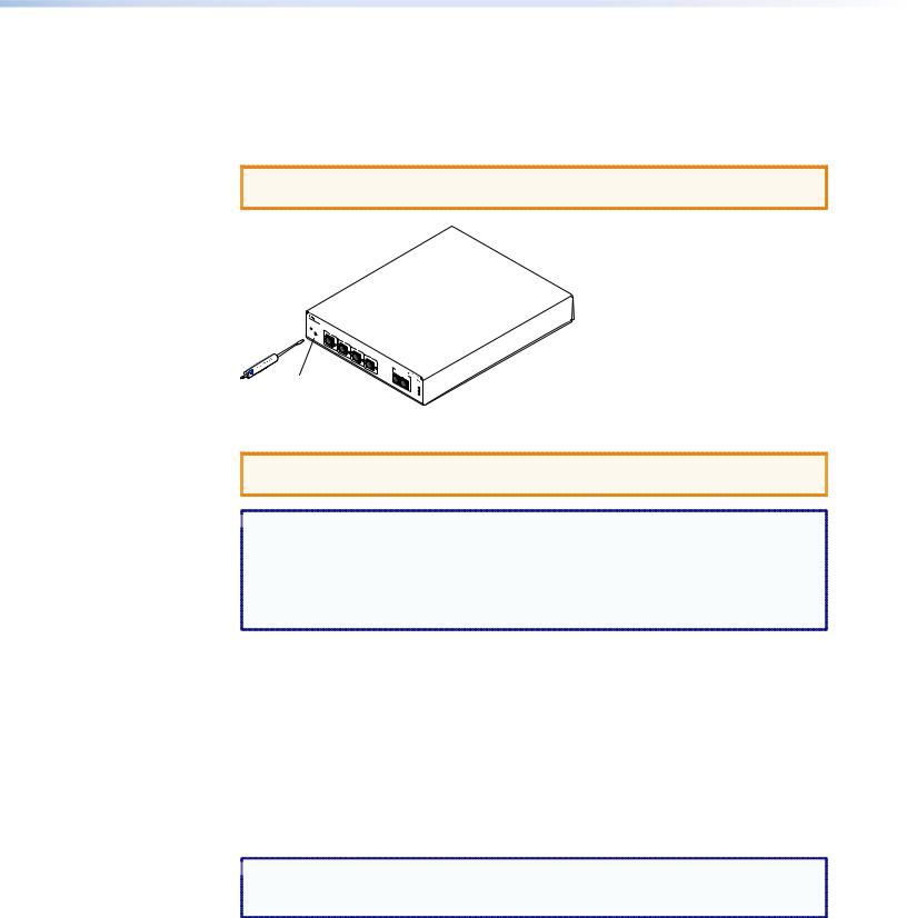
4.Connect an active LAN Ethernet cable to the RJ-45 port on the rear panel to establish a link to the network.
5.Set up an IP address for the PCS4 (see “HTML Configuration and Control” or “SIS Programming and Control”).
6.Plug the desired devices into the power receptacles on the PCS4 rear panel.
7.Press the front panel buttons to power on the receptacles.
8.Turn on the output devices.
9.Configure the PCS4 interface through the front panel, Telnet, or the web pages, then access the unit using an Internet browser.
IPL T PCS4 • Installation and Rear Panel |
4 |

Rear Panels
100-120V |
10A |
1 |
2 |
3 |
4 |
S/N XXXXXXXXX E0000 0408 |
|
|
|
|
5 |
||||||
|
|
|
|
|
|
00-05-A6-XX-XX-XX |
||
|
|
|
|
|
|
ALARM |
LAN |
|
|
|
|
|
|
|
|
|
|
50/60 Hz |
|
|
100-120V TOTAL LOAD 10A MAX |
|
|
|
|
|
1 |
|
|
|
2 |
|
3 |
4 |
|
Figure 4. IPL T PCS4 Rear Panel (120 VAC) |
|
|
|
|
||||
200-240V |
10A |
1 |
2 |
3 |
4 |
S/N XXXXXXXXX E0000 0408 |
|
|
|
|
5 |
||||||
|
|
|
|
|
|
00-05-A6-XX-XX-XX |
||
|
|
|
|
|
|
|
LAN |
|
|
|
|
|
|
|
ALARM |
|
|
50/60 Hz |
|
200-240V TOTAL LOAD 10A MAX |
|
|
|
|
||
1 |
|
|
|
2 |
|
3 |
4 |
|
Figure 5. IPL T PCS4i Rear Panel (220 VAC)
APower connector — Connect a power cord from the AC power supply to this male IEC power input receptacle.
 NOTE: For the IPL T PCS4, use the supplied 14 AWG IEC power cord (part
  number 27 407-01).
BOutput receptacles — Connect power cords from up to four devices to these three-prong female U. S. (IPL T PCS4) or IEC (IPL T PCS4i) power output receptacles.
CAlarm relay — Connect a relay-controllable detection device to this single-pole, single-throw relay connector. (The default condition for this relay is normally open.)
DLAN connector and LEDs — An Ethernet connection can be used on an ongoing basis to monitor and control the PCS4 (and the devices connected to it).
•RJ-45 port — Plug a patch cable into this RJ 45 female socket, and connect the other end to a network switch, hub, router, or PC.
•Link LED — This green LED lights to indicate a good network connection.
•Activity LED — This yellow LED blinks to indicate network activity.
LAN
RJ-45
Port
Link |
LED |
Activity
LED
EUID # label — Contains the unique User ID number (MAC address) of the unit (for example, 00-05-A6-00-00-01).
IPL T PCS4 • Installation and Rear Panel |
5 |
Setting Up the LAN Port
LAN Port Cabling
•For 10Base-T (10 Mbps) networks, use a Category 3 or better cable.
•For 100Base-T networks, use a Category 5 cable.
•Use a straight-through cable to connect to a switch, hub, or router.
•Use a crossover cable to connect directly to a PC. Wire the connector as shown in the tables below.
Pins:
12345678
Insert Twisted
Pair Wires
RJ-45
Connector
Figure 6.
Crossover Cable
|
End 1 |
End 2 |
Pin |
Wire Color |
Wire Color |
|
|
|
|
|
|
1 |
White-orange |
White-green |
|
|
|
2 |
Orange |
Green |
|
|
|
3 |
White-green |
White-orange |
|
|
|
4 |
Blue |
Blue |
|
|
|
5 |
White-blue |
White-blue |
|
|
|
6 |
Green |
Orange |
7 |
White-brown |
White-brown |
|
|
|
8 |
Brown |
Brown |
|
|
|
|
T568A |
T568B |
A cable that is wired as T568A at one end and T568B at the other (Tx and Rx pairs reversed) is a "crossover" cable.
Straight-through Cable
Pin |
End 1 |
End 2 |
Wire Color |
Wire Color |
|
|
|
|
|
|
|
1 |
White-orange |
White-orange |
|
|
|
|
|
|
2 |
Orange |
Orange |
|
|
|
3 |
White-green |
White-green |
|
|
|
4 |
Blue |
Blue |
|
|
|
5 |
White-blue |
White-blue |
|
|
|
6 |
Green |
Green |
|
|
|
7 |
White-brown |
White-brown |
|
|
|
8 |
Brown |
Brown |
|
|
|
|
T568B |
T568B |
A cable that is wired the same at both ends is called a "straight-through" cable, because no pin or pair assignments are swapped.
RJ-45 Connector Wiring
Configuring the LAN Port
You need to configure the LAN port before using it. You can configure the settings via either SIS commands or the embedded web pages (see “HTML Configuration and Control” or “SIS Programming and Control” for details).
LAN port factory defaults:
Link speed and duplex: |
Auto Detect |
Unit IP address: |
192.168.254.254 |
Subnet Mask: |
255.255.0.0 |
Gateway IP address: |
0.0.0.0 |
DHCP: |
Off |
Connecting the Devices
Connect the cables to the rear panel as follows:
1.Plug the Ethernet cable from your network into the LAN port on the rear panel.
2.Plug the IPL T PCS4 power cord into a wall outlet. All front panel LEDs flash on briefly; only the power and Ethernet LEDs remain lit. (No receptacle lights should remain lit.)
 NOTE: A label covers the power receptacle on the IPL T PCS4 (US version),
reminding you that you must use the supplied 14 AWG power cord for the
PCS4 to function properly. Remove this label before connecting the power cord to the unit.
IPL T PCS4 • Installation and Rear Panel |
6 |

3.Plug the power cord of each device to be monitored into one of the receptacles on the back panel of the PCS4.
4.If desired, connect a relay-controllable siren or other detection device to the Alarm relay on the rear panel.
 NOTE: The alarm relay cannot be set up from the front panel. You must use either
SIS commands or the web pages to configure it (see the Power receptacle
Monitoring and Alarm Functions SIS commands in the “SIS Programming and Control” section).
IPL T PCS4 • Installation and Rear Panel |
7 |
Front Panel
Features and
Operation
This section contains a description of the IPL T PCS4 and IPL T PCS4i front panel features and instructions for setting up the PCS4 using the front panel. The following topics are discussed:
•Front Panel Features
•Setting Up the System Using the Front Panel
•Resetting the Unit
Front Panel Features
7 |
6 |
7 |
6 |
7 |
6 |
7 |
6 |
|
IPL T PCS4 |
|
|
4 |
SET REFERENCE |
|
|
1 |
2 |
3 |
STANDBY FULL |
|
|
1 |
F |
F |
F |
F |
100 |
|
R |
|
|
|
LINK |
5 |
|
|
|
|
|
|
ACT |
|
|
S |
S |
S |
S |
|
|
|
2 |
|
3 |
|
4 |
|
Figure 7. IPL T PCS4 and IPL T PCS4i Front Panel
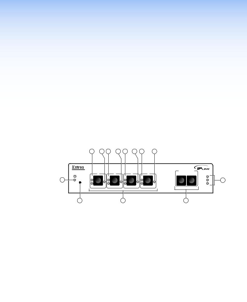
APower LED (green) — When this LED is lit, the PCS4 or PCS4i power control interface is receiving power and is running. When the unit is being reset, this LED blinks the appropriate number of times to indicate the reset mode that has been entered.
BReset button (recessed) — Use the tip of a Phillips screwdriver or a pointed stylus to press this recessed button to reset the unit in one of four Reset modes (see “Resetting the Unit” for details on reset modes and on using this button).
CPower control buttons 1-4 — Press these buttons to switch power on and off to the output receptacle with the corresponding number on the rear panel. These buttons are
also used, along with the Set Reference buttons (D), to set the Full and Standby power thresholds.
DSet Reference (Power threshold) buttons — Press these buttons to set the indicator
LEDs for each receptacle to indicate whether the attached devices are operating at Full or Standby power level.
IPL T PCS4 • Front Panel Features and Operation |
8 |

ELAN status LEDs — These three LEDs show the status of the Ethernet connection as follows:
•100 — When lit, indicates a 100 Mbps connection speed. Otherwise, the connection speed is 10 Mbps.
•Link — Indicates that the interface has an active network connection.
•Act — (Activity) Blinks while data is being sent or received.
FPower LEDs (red) — (One for each receptacle) Indicate that power is being supplied to the attached device.
GPower Management (threshold) LEDs — (Set of two for each receptacle) After the power thresholds have been set, these LEDs indicate the status of the attached device as follows:
•F — Indicates that power is at or above the Full reference threshold.
•S — Indicates that power is at or above the Standby reference threshold, and below the Full threshold.
Setting Up the System Using the Front Panel
The PCS4 can be set up and operated by using:
•The front panel controls
•A computer or other device using an Ethernet connection and IP protocol (Telnet or a web browser)
The following system setup procedures can be performed using the front panel, the embedded web pages, or the SIS commands. Some settings can be adjusted only through a host computer, either using SIS commands via Telnet or using the PCS4 embedded web pages. For details on setup and control via Ethernet, see the “SIS Programming and Control” or the “HTML Configuration and Control” section.
Setting Up Power Control
To set up control of power to the devices plugged into the PCS4 receptacles, do the following for each device:
1. On the PCS4 front panel, press and release the power control button |
1 |
|
F |
||
for the receptacle into which the device is plugged. |
||
|
||
The Power LED at the right of the button lights and remains |
|
|
lit while the receptacle is powered on. It is unlit when the |
S |
|
receptacle is powered off. |
|
2. Power on the device, using its own power switch.
Power
LED
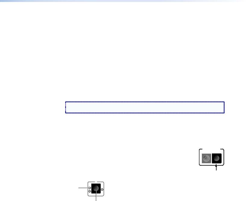
Setting Power Level Reference Thresholds
You can set the PCS4 to notify you when the power level of a connected device drops from Full to Standby or to None. For each device, you can use front panel controls to set the reference threshold (Full or Standby) at which a notification is triggered.
Until a threshold is set for a receptacle the first time, the status displayed for the receptacle on the web page or given in response to SIS queries is Not Set. Once a threshold has been set, the receptacle status defaults to None if all thresholds are cleared (see “None and Not Set thresholds,” later in this section, for more information).
IPL T PCS4 • Front Panel Features and Operation |
9 |
There are two common types of power for electronic devices: soft and hard.
•Soft power devices normally have three power states: On, Standby, and Off. Such devices include projectors, DVD players, and VCRs.
Example: On soft power devices, the Standby mode allows the unit to be powered to its Full power mode via RS-232 commands or a remote. Pressing a PCS4 receptacle
button to Off when the receptacle is connected to a device that supports Standby power causes the device to power off.
•Hard power devices normally have two power states: On and Off. These devices include Extron switchers and interfaces.
Example: On Extron switchers, there is no power button or Standby condition, and the unit power can be set only to On and Off from the PCS4 front panel. Therefore, when the power is on, it is at Full power, and can be set for Full reference threshold.
The Full and Standby reference thresholds must be configured with the device attached to the PCS4 receptacle. The thresholds must be set in the correct order, with Full being set first. Follow these steps to set the threshold for each device, using the front panel. (These thresholds also can be configured using the web pages or SIS commands.)
 NOTE: The Full threshold must be set first. If Standby is set first, the Standby reference
  setting is removed by the setting of the Full reference threshold.
1.Connect a device to a power output receptacle on the IPL T PCS4. Make a note of the receptacle number to which you connected it (1 through 4).
2.Press the corresponding front panel button to activate the receptacle. Check to ensure that the Power LED for the receptacle is lit.
Setting the Full power threshold
1. |
Power on the attached device. |
SET REFERENCE |
STANDBY FULL |
||
2. |
Press and hold the Full button on the PCS4 front panel (shown at right). |
|
3. |
While holding the Full button, press and release the button for the |
|
|
receptacle into which the device is plugged. Both the F (Full) LED and the |
|
S (Standby) LED for the selected receptacle blink twice. Only the Full LED remains lit.
1
Full |
F |
|
|
LED |
|
|
S |
Receptacle Button
4. Release the Full button. The Full threshold for the receptacle is now set.
IPL T PCS4 • Front Panel Features and Operation 10
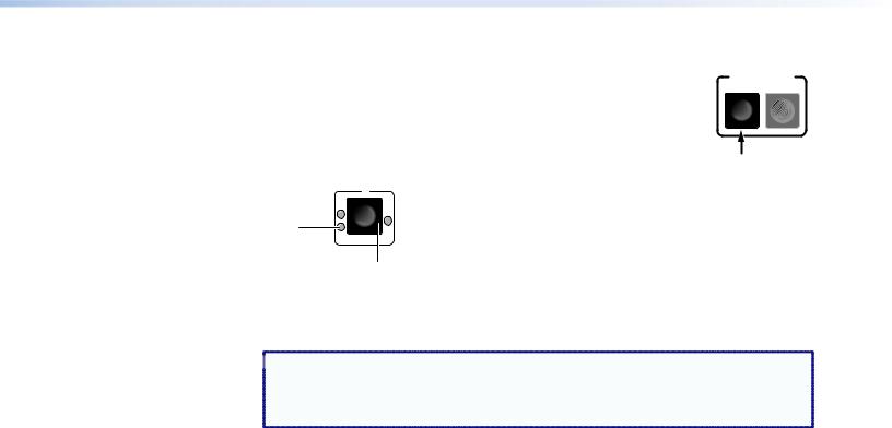
Setting the Standby power threshold
1. |
Power off the attached device. |
SET REFERENCE |
STANDBY FULL |
||
2. |
Press and hold the Standby button (shown at right). |
|
3. |
While holding down the Standby button, press and release the |
|
|
receptacle button for the same device for which you set the Full |
|
threshold. The Standby LED for the selected receptacle blinks twice and remains lit.
1
F
Standby
LED
S
Receptacle Button
4.Release the Standby button.
5.Repeat steps 1 through 9 for any other receptacles to which you have connected devices to be controlled through the PCS4.
 NOTE: Settings that are made via the front panel for power output receptacles
and reference thresholds take approximately two minutes to be stored in
memory. If you recycle power too soon after settings have been made, the settings are lost.
These threshold settings are preserved if the PCS4 AC power is recycled or if power is removed from an attached device. For example:
If the receptacle |
And the power level... |
The receptacle... |
|
is set to... |
|||
|
|
||
|
|
|
|
Full |
drops below the stored threshold |
F (Full) led shuts off, and the |
|
S (Standby) LED lights. |
|||
|
|
||
|
drops below the stored Standby |
S LED shuts off. |
|
Standby |
threshold |
||
|
|||
|
exceeds the stored Standby threshold |
F LED lights. |
To indicate that the configuration has been saved, both the Standby LED and the Full LED light and remain lit when those thresholds are selected.
None and Not Set thresholds
When a Full or Standby reference threshold has been set for a receptacle at some time, and neither threshold is detected, a threshold status of None appears on the web page or can be the response to SIS queries. None also appears if the receptacle is powered off. The None threshold is a state that is detected; it cannot be set manually.
If a receptacle has never been set to a Full or Standby reference threshold, its threshold status is shown as Not Set on the web page and in response to SIS queries. Not Set is the default setting for reference thresholds.
IPL T PCS4 • Front Panel Features and Operation 11

Clearing thresholds
To remove the reference threshold settings from any receptacle:
1.Shut off power to the receptacle that you want to clear by pressing its button on the front panel. The red LED to the right of the button shuts off.
2.Press and hold the Standby or Full button while pressing and releasing the receptacle button. All three receptacle LEDs flash twice, indicating that the settings have been cleared.
3.Release the Standby or Full button that you were holding.
If desired, you can now turn power to the receptacle on again by pressing its button.
Grouping Receptacles
Two or more power receptacles can be grouped so that both their connected devices can be controlled simultaneously. To group receptacles using the front panel, follow these steps for each receptacle:
1.Place the receptacle in configuration mode by pressing and holding its receptacle button for 2 seconds. The green Power LED on the front panel flashes continually, indicating that the unit is in configuration mode.
2.Press each receptacle button repeatedly to cycle through the available group selections, indicated by the LEDs beside the button, until you arrive at the setting you want for the receptacle:
•No LEDs lit — No groups (The receptacle will not be part of any grouping.)
•S LED lit — Group 1
•F LED lit — Group 2
•Red (power) LED lit — Group 3
3.Press either the Standby or the Full button to exit configuration mode.
Ungrouping receptacles
To remove a receptacle from a grouping:
1.Place the receptacle in configuration mode by pressing and holding its button for two seconds, until the green power LED flashes continually.
2.Press the receptacle button repeatedly until none of its LEDs are lit (indicating no groups).
3.Press the Standby or Full button to exit configuration mode.
Front panel Security Lockout (Executive Mode)
When the PCS4 is in executive mode, it does not accept commands from the front panel. If any button is pressed while the unit is in executive mode, the Power LED flashes three times, indicating that the input from the front panel is not being accepted.
To enter or exit executive mode, press and hold the Standby and Full buttons simultaneously for 2 seconds. The front panel Power LED flashes three times to indicate that the mode has been switched.
 NOTE: If power to the PCS4 is recycled while the unit is in executive mode, the PCS4
  remains in executive mode.
IPL T PCS4 • Front Panel Features and Operation 12
Resetting the Unit
There are four ways to reset the PCS4 unit (called modes 1, 3, 4, and 5 for the sake of comparison with other Extron IPL products). Reset the unit by pressing the Reset button on the front panel (see “Front Panel Features” for the button location). This button is
recessed; it can be accessed with a pointed stylus, ballpoint pen, or small Phillips screwdriver.
 CAUTION: The reset modes described on the following pages break all TCP/IP connections by closing all sockets to the unit.
IPLT 
 PCS4
PCS4
R
F |
1 |
|
|
|
S |
F |
2 |
|
|
|
S |
F |
3 |
|
|
|
S |
F |
4 |
|
|
|
S |
|
Recessed Reset Button
SET STANREFE  DBY RFEUNLCLE

100 LINK ACT
Figure 8. Reset Button
 CAUTION: Review the reset modes carefully. Use of the wrong reset mode may result in
  unintended loss of flash memory programming or a unit reboot.
 NOTES: • If the Reset button is continually held in, the LEDs pulse (blink) every
3 seconds, and the PCS4 is put in a different mode, corresponding to the
underscored notes in modes 3 through 5. The mode 5 LED blinks three times,
the third blink indicating that it is the last mode.
• The reset modes are separate functions, not a progression from mode 1 to mode 5.
Mode 1
Activation |
Hold in the Reset button while applying power to the unit. |
|
|
Result |
Returns the unit to the default base firmware that was shipped |
|
with the PCS4 from the factory. Event scripting does not start when |
|
the unit is powered on in this mode. |
|
|
Purpose and notes |
Use mode 1 to remove a version of firmware if incompatibility |
|
issues arise. All user files and settings are maintained. User web |
|
pages may not work correctly if you are using an earlier firmware |
|
version. |
 NOTE: After a mode 1 reset, the factory-installed firmware version remains in effect
only until the unit is powered off. After a power cycle, the PCS4 returns to the firmware that was installed prior to the mode 1 reset.
IPL T PCS4 • Front Panel Features and Operation 13

Mode 3
Activation |
Hold the Reset button in until the Power LED blinks once |
|
(approximately 3 seconds). Release it, then immediately press it |
|
again momentarily (for less than 1 second). |
|
NOTE: Nothing happens if the momentary press does not |
|
occur within 1 second. |
Result |
Turns events on or off, depending on their current state. During |
|
resetting, the reset LED flashes two times if events are starting and |
|
three times if events are stopping. |
Purpose and notes This mode is used for troubleshooting.
Mode 4
Activation |
Hold the Reset button in until the Power LED blinks twice |
|
(approximately 6 seconds). Release it, then immediately press it |
|
again momentarily (for less than 1 second). The Power LED blinks |
|
four times in quick succession, confirming a mode 4 reset. |
|
NOTE: Nothing happens if the momentary press does not |
|
occur within 1 second. |
Result |
Reset mode 4 does the following: |
•Enables ARP program capability.
•Sets the IP address back to factory IP settings.
•Sets the subnet mask back to factory default.
•Sets the gateway address back to factory default.
•Sets port mapping back to factory default.
•Turns DHCP off.
•Turns events off.
Purpose and notes Mode 4 enables you to set IP address information using ARP and the MAC address.
Mode 5
Activation |
Hold in the Reset button until the Power LED blinks three times |
|
(approximately 9 seconds). Release it, then immediately press it |
|
again momentarily (for less than 1 second). The power LED blinks |
|
four times in quick succession, confirming a mode 5 reset. |
|
NOTE: Nothing happens if the momentary press does not occur |
|
within 1 second. |
Result |
Performs a complete reset to factory defaults (except for the |
|
firmware). |
Purpose and notes Mode 5 is useful if you want to start over with control software configuration and to replace events.
IPL T PCS4 • Front Panel Features and Operation 14
HTML
Configuration and
Control
The IPL T PCS4 must be configured before use, or it cannot control other devices. In addition to using the buttons on the PCS4 front panel, you can configure and control the PCS4 via any computer attached to a LAN by using the embedded web pages or SIS commands. This section describes the web pages and provides instructions for using them to configure the IPL T PCS4 series interfaces. Topics include:
•Configuring the Hardware
•Using the Embedded Web Pages
•Custom Web Pages
•A/V Device Power Control
Configuring the Hardware
To function together, both the computer and the PCS4 must be configured correctly. The computer must be network-capable with the proper protocols, and the PCS4 must be set up so it can be connected to a LAN (local area network). Note that some settings can be configured only via Internet protocol.
For your computer to communicate with the PCS4, it must be equipped with an network interface card and an HTML browser. To allow your computer to work with Extron Ethernetcontrolled products, the TCP/IP protocol must be installed and properly configured.
Setting Up the Computer Using ARP
The Address Resolution Protocol (ARP) command provides a quick way to set up an IP address for the PCS4, using your computer. The ARP commands tell your computer to associate the PCS4 Media Access Control (MAC) address with an IP address that you assign. After entering the ARP command, enter a ping command to access the PCS4 at its new address to confirm the address has been successfully changed.
1.Obtain a valid IP address for your PCS4 from your network administrator.
2.Obtain the PCS4 MAC address (UID#) from the label on its rear panel. The MAC address should have the following format:
00-05-A6-xx-xx-xx
where x can be a letter or a number.
IPL T PCS4 • HTML Configuration and Control 15
Loading...