


 Loading...
User’s Manual
INTERCOM |
MIC ON |
INTERCOM |
|
|
MIC ON |
|
|
|
LEVEL |
||
|
|
|
|
|
HIGH |
|
|
|
|
|
MED |
|
|
|
|
|
LOW |
|
PUSH TO TALK |
|
PUSH TO TALK |
||
HELP |
ROOM |
LAB |
ADMIN |
HELP |
SECURITY |
LAB |
ADMIN |
|
DESK |
101 |
OFFICE |
DESK |
OFFICE |
||||
|
|
|
||||||
1 |
2 |
3 |
4 |
1 |
2 |
3 |
4 |
LEVEL |
IPI 204 |
|
IPI 104 |
INTERCOM |
MIC ON |
INTERCOM |
MIC ON |
LEVEL
HIGH
 MED
MED
LOW
PUSH TO |
HELP |
PUSH TO |
HELP |
TALK |
DESK |
TALK |
DESK |
LEVEL |
IPI 201 |
IPI 101 |
IPI 100 Series
IPI 200 Series
MediaLink™ IP Intercom™ Interfaces
68-1170-01 Rev. C
12 08
Precautions
Safety Instructions • English
Thissymbolisintendedtoalerttheuserofimportant operatingandmaintenance(servicing)instructionsin the literature provided with the equipment.
This symbol is intended to alert the user of the presence of uninsulated dangerous voltage within the product’s enclosure that may present a risk of electric shock.
Caution
Read Instructions • Read and understand all safety and operating instructions before using the equipment.
Retain Instructions • The safety instructions should be kept for future reference.
Follow Warnings • Follow all warnings and instructions marked on the equipment or in the user information.
Avoid Attachments • Do not use tools or attachments that are not recommended by the equipment manufacturer because they may be hazardous.
Consignes de Sécurité • Français
Ce symbole sert à avertir l’utilisateur que la documentation fournie avec le matériel contient des instructionsimportantesconcernantl’exploitationet la maintenance (réparation).
Ce symbole sert à avertir l’utilisateur de la présence dansleboîtierdel’appareilde tensionsdangereuses non isolées posant des risques d’électrocution.
Attention
Lire les instructions• Prendre connaissance de toutes les consignes de sécurité et d’exploitation avant d’utiliser le matériel.
Conserver les instructions• Ranger les consignes de sécurité afin de pouvoir les consulter à l’avenir.
Respecter les avertissements • Observer tous les avertissements et consignes marqués sur le matériel ou présentés dans la documentation utilisateur.
Eviter les pièces de fixation • Ne pas utiliser de pièces de fixation ni d’outils non recommandés par le fabricant du matériel car cela risquerait de poser certains dangers.
Warning
Power sources • This equipment should be operated only from the power source indicated on the product. This equipment is intended to be used with a main power system with a grounded (neutral) conductor. The third (grounding) pin is a safety feature, do not attempt to bypass or disable it.
Power disconnection • To remove power from the equipment safely, remove all power cords from the rear of the equipment, or the desktop power module (if detachable), or from the power source receptacle (wall plug).
Power cord protection • Power cords should be routed so that they are not likely to be stepped on or pinched by items placed upon or against them.
Servicing • Refer all servicing to qualified service personnel. There are no userserviceable parts inside. To prevent the risk of shock, do not attempt to service this equipment yourself because opening or removing covers may expose you to dangerous voltage or other hazards.
Slots and openings • If the equipment has slots or holes in the enclosure, these are provided to prevent overheating of sensitive components inside. These openings must never be blocked by other objects.
Lithium battery • There is a danger of explosion if battery is incorrectly replaced. Replace it only with the same or equivalent type recommended by the manufacturer. Dispose of used batteries according to the manufacturer’s instructions.
Avertissement
Alimentations• Ne faire fonctionner ce matériel qu’avec la source d’alimentation indiquée sur l’appareil. Ce matériel doit être utilisé avec une alimentation principale comportant un fil de terre (neutre). Le troisième contact (de mise à la terre) constitue un dispositif de sécurité : n’essayez pas de la contourner ni de la désactiver.
Déconnexion de l’alimentation• Pour mettre le matériel hors tension sans danger, déconnectez tous les cordons d’alimentation de l’arrière de l’appareil ou du module d’alimentation de bureau (s’il est amovible) ou encore de la prise secteur.
Protection du cordon d’alimentation • Acheminer les cordons d’alimentation de manière à ce que personne ne risque de marcher dessus et à ce qu’ils ne soient pas écrasés ou pincés par des objets.
Réparation-maintenance • Faire exécuter toutes les interventions de réparationmaintenance par un technicien qualifié. Aucun des éléments internes ne peut être réparé par l’utilisateur. Afin d’éviter tout danger d’électrocution, l’utilisateur ne doit pas essayer de procéder lui-même à ces opérations car l’ouverture ou le retrait des couvercles risquent de l’exposer à de hautes tensions et autres dangers.
Fentes et orifices • Si le boîtier de l’appareil comporte des fentes ou des orifices, ceux-ci servent à empêcher les composants internes sensibles de surchauffer. Ces ouvertures ne doivent jamais être bloquées par des objets.
Lithium Batterie • Il a danger d’explosion s’ll y a remplacment incorrect de la batterie. Remplacer uniquement avec une batterie du meme type ou d’un ype equivalent recommande par le constructeur. Mettre au reut les batteries usagees conformement aux instructions du fabricant.
Sicherheitsanleitungen • Deutsch
Dieses Symbol soll dem Benutzer in der im Lieferumfang enthaltenen Dokumentation besonders wichtige Hinweise zur Bedienung und Wartung (Instandhaltung) geben.
DiesesSymbolsolldenBenutzerdaraufaufmerksam machen, daß im Inneren des Gehäuses dieses ProduktesgefährlicheSpannungen,dienichtisoliert sind und die einen elektrischen Schock verursachen können, herrschen.
Achtung
Lesen der Anleitungen • Bevor Sie das Gerät zum ersten Mal verwenden, sollten Sie alle Sicherheits-und Bedienungsanleitungen genau durchlesen und verstehen.
Aufbewahren der Anleitungen • Die Hinweise zur elektrischen Sicherheit des Produktes sollten Sie aufbewahren, damit Sie im Bedarfsfall darauf zurückgreifen können.
Befolgen der Warnhinweise • Befolgen Sie alle Warnhinweise und Anleitungen auf dem Gerät oder in der Benutzerdokumentation.
Keine Zusatzgeräte • Verwenden Sie keine Werkzeuge oder Zusatzgeräte, die nicht ausdrücklich vom Hersteller empfohlen wurden, da diese eine Gefahrenquelle darstellen können.
Instrucciones de seguridad • Español
Este símbolo se utiliza para advertir al usuario sobre instrucciones importantes de operación y mantenimiento (o cambio de partes) que se desean destacar en el contenido de la documentación suministrada con los equipos.
Este símbolo se utiliza para advertir al usuario sobre la presencia de elementos con voltaje peligroso sin protección aislante, que puedan encontrarse dentro de la caja o alojamiento del producto, y que puedan representar riesgo de electrocución.
Precaucion
Leer las instrucciones • Leer y analizar todas las instrucciones de operación y seguridad, antes de usar el equipo.
Conservar las instrucciones • Conservar las instrucciones de seguridad para futura consulta.
Obedecer las advertencias • Todas las advertencias e instrucciones marcadas en el equipo o en la documentación del usuario, deben ser obedecidas.
Evitar el uso de accesorios • No usar herramientas o accesorios que no sean especificamente recomendados por el fabricante, ya que podrian implicar riesgos.
Vorsicht
Stromquellen • Dieses Gerät sollte nur über die auf dem Produkt angegebene Stromquelle betrieben werden. Dieses Gerät wurde für eine Verwendung mit einer Hauptstromleitung mit einem geerdeten (neutralen) Leiter konzipiert. Der dritte
Kontakt ist für einen Erdanschluß, und stellt eine Sicherheitsfunktion dar. Diese sollte nicht umgangen oder außer Betrieb gesetzt werden.
Stromunterbrechung • Um das Gerät auf sichere Weise vom Netz zu trennen, sollten Sie alle Netzkabel aus der Rückseite des Gerätes, aus der externen Stomversorgung (falls dies möglich ist) oder aus der Wandsteckdose ziehen.
Schutz des Netzkabels • Netzkabel sollten stets so verlegt werden, daß sie nicht im Weg liegen und niemand darauf treten kann oder Objekte daraufoder unmittelbar dagegengestellt werden können.
Wartung • Alle Wartungsmaßnahmen sollten nur von qualifiziertem Servicepersonal durchgeführt werden. Die internen Komponenten des Gerätes sind wartungsfrei. Zur Vermeidung eines elektrischen Schocks versuchen Sie in keinem Fall, dieses Gerät selbst öffnen, da beim Entfernen der Abdeckungen die Gefahr eines elektrischen Schlags und/oder andere Gefahren bestehen.
Schlitze und Öffnungen • Wenn das Gerät Schlitze oder Löcher im Gehäuse aufweist, dienen diese zur Vermeidung einer Überhitzung der empfindlichen Teile im
Inneren. Diese Öffnungen dürfen niemals von anderen Objekten blockiert werden.
Litium-Batterie • Explosionsgefahr, falls die Batterie nicht richtig ersetzt wird. Ersetzen Sie verbrauchte Batterien nur durch den gleichen oder einen
vergleichbaren Batterietyp, der auch vom Hersteller empfohlen wird. Entsorgen Sie verbrauchte Batterien bitte gemäß den Herstelleranweisungen.
Advertencia
Alimentación eléctrica • Este equipo debe conectarse únicamente a la fuente/tipo de alimentación eléctrica indicada en el mismo. La alimentación eléctrica de este equipo debe provenir de un sistema de distribución general con conductor neutro
a tierra. La tercera pata (puesta a tierra) es una medida de seguridad, no puentearia ni eliminaria.
Desconexión de alimentación eléctrica • Para desconectar con seguridad la acometida de alimentación eléctrica al equipo, desenchufar todos los cables de alimentación en el panel trasero del equipo, o desenchufar el módulo de alimentación (si fuera independiente), o desenchufar el cable del receptáculo de la pared.
Protección del cables de alimentación • Los cables de alimentación eléctrica se deben instalar en lugares donde no sean pisados ni apretados por objetos que se puedan apoyar sobre ellos.
Reparaciones/mantenimiento • Solicitar siempre los servicios técnicos de personal calificado. En el interior no hay partes a las que el usuario deba acceder. Para evitar riesgo de electrocución, no intentar personalmente la reparación/mantenimiento de este equipo, ya que al abrir o extraer las tapas puede quedar expuesto a voltajes peligrosos u otros riesgos.
Ranuras y aberturas • Si el equipo posee ranuras o orificios en su caja/alojamiento, es para evitar el sobrecalientamiento de componentes internos sensibles. Estas aberturas nunca se deben obstruir con otros objetos.
Batería de litio • Existe riesgo de explosión si esta batería se coloca en la posición incorrecta. Cambiar esta batería únicamente con el mismo tipo (o su equivalente) recomendado por el fabricante. Desachar las baterías usadas siguiendo las instrucciones del fabricante.
•
有重要的操作和维护说明。

•
•
•
•
•
•
••
•
•
A
FCC Class A Notice
This equipment has been tested and found to comply with the limits for a Class A digital device, pursuant to part 15 of the FCC Rules. Operation is subject to the following two conditions: (1) this device may not cause harmful interference, and (2) this device must accept any interference received, including interference that may cause undesired operation. The Class A limits are designed to provide reasonable protection against harmful interference when the equipment is operated in
a commercial environment. This equipment generates, uses, and can radiate radio frequency energy and, if not installed and used in accordance with the instruction manual, may cause harmful interference to radio communications. Operation of this equipment in a residential area is likely to cause harmful interference, in which case the user will be required to correct the interference at his own expense.

This page has been intentionally left blank.
Quick Start Guide — IPI 101, IPI 104
WInstallation and service must be performed by authorized personnel only. These products must be used with UL approved, grounded electrical boxes.
To install an Extron IP Intercom® Sytem, follow the steps below:
Step 1
Turn all of the equipment off and disconnect the power cords.
Step 2
Select the installation location and install an electrical wall box for each IPI unit and MLC 226 IP in the system. See “Sample
Applications” on page 2-8 for ideas on designing an intercom system.
Step 3
Install button labels in each of the IPI’s buttons. See page 2-2 for instructions.
Step 4
Mount each IPI into an AAP wallplate or device faceplate, as described on page 2-4.
Step 5
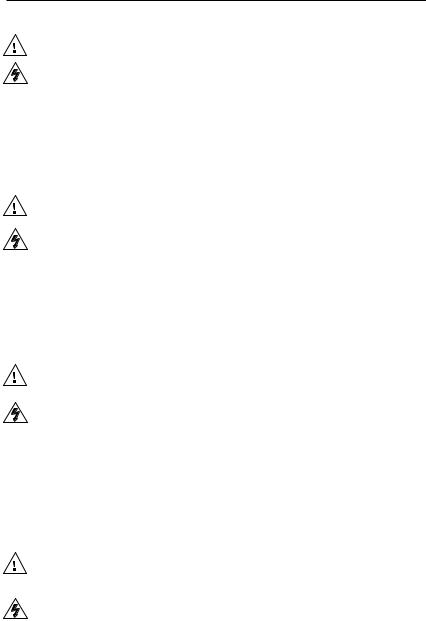
Connect each IPI to an MLC 226 IP via the RJ-45 intercom ports, using a standard CAT 5, CAT 5e, or CAT 6 straight through network cable. See “IPI Rear Panel Features and Cabling“ on page 2-6.
IPI 101 AAP or IPI 104 AAP Rear Panel
R |
INTERCOM |
|
AUDIO OUT |
MLC 226 IP Rear Panel
|
HOST |
|
CONTROL |
|
1=DIGITAL I/O |
|
2=Tx 3=Rx 5=GND |
|
38400, N, 8, 1 |
LAN |
PRESS TAB WITH |
TWEEKER TO REMOVE |
Step 6
Cable each MLC 226 IP to other devices: connect the MLC’s LAN port to the local network via a standard network cable with RJ-45 connector, and, if desired, cable the rear panel Audio connector to speakers for local audio output. Cable other devices (control modules, SCP, IR Emitters) to the MLC as needed.
IPI 100 Series, IPI 200 Series • Quick Start Guide QS-1

Quick Start Guide — IPI 101, IPI 104, cont’d
Step 7
Install each MLC 226 IP and IPI into the wallboxes you installed in step 2 above.
Step 8
Connect the console PC(s) to the network.
Step 9
Connect the PC(s) and MLC(s) to power sources and turn on the
PC(s).
Step 10
Configure the MLC 226 IP. Refer to the MLC 226 IP User’s Manual and the Global Configurator help file for instructions.
Step 11
Install the Extron IP Intercom HelpDesk™ software on a PC. See page 4-2 for software installation instructions.
Step 12
Use the IP Intercom HelpDesk software and Configuration Utility to configure all IPI units that are part of the system. See “Setup procedure” on page 4-20 of this manual for instructions on configuring the IPIs.
QS-2 IPI 100 Series, IPI 200 Series • Quick Start Guide

Quick Start Guide — IPI 201, IPI 204
WInstallation and service must be performed by authorized personnel only. These products must be used with UL approved, grounded electrical boxes.
To install an Extron IP Intercom® System, follow the steps below:
Step 1
Turn all of the equipment off and disconnect the power cords.
Step 2
Select the installation location and install an electrical wall box for each IPI 201 or IPI 204 unit in the system. See “Sample Applications” on page 2-8 for ideas on designing an intercom system.
Step 3
Install button labels in each of the IPI’s buttons. See page 2-2 for instructions.
Step 4
Mount each IPI into an AAP wallplate, mounting bracket for 2-gang wallplates or device faceplate, as described on page 2-4.
Step 5
Cable each IPI to other devices: connect the IPI’s LAN port to the local network via a standard network cable with RJ-45 connector, and, if desired, cable the rear panel Audio connector (see page 2-8) to speakers for local audio output.
Step 6
Install each IPI into the wallboxes you installed in step 2 above.
Step 7
Connect the console PC(s) to the network.
Step 8
Connect the PC(s) and IPI(s) to power sources and turn on the PC(s).
Step 10
Install the Extron IP Intercom HelpDesk software on a PC. See page 4-2 for software installation instructions.
Step 11
Use the IP Intercom HelpDesk software and Configuration Utility to configure all IPI units that are part of the system. See “Setup procedure” on page 4-20 for instructions on configuring the IPIs.
IPI 100 Series, IPI 200 Series • Quick Start Guide QS-3

This page has been intentionally left blank.

Table of Contents
Chapter One • Introduction ................................................... |
1-1 |
About this Manual..................................................................... |
1-2 |
Terms used in this manual..................................................... |
1-2 |
Additional reference material............................................... |
1-2 |
About the IP Intercom Modules............................................ |
1-2 |
Features......................................................................................... |
1-4 |
System Requirements............................................................... |
1-4 |
Chapter Two • Installation ...................................................... |
2-1 |
UL Requirements........................................................................ |
2-2 |
Installing or Replacing Button Labels.................................. |
2-2 |
Mounting the IPI 101 or IPI 104 into an AAP Wall Plate or |
|
Device Faceplate......................................................................... |
2-4 |
Mounting the IPI 201 or IPI 204 into an AAP Wall Plate or |
|
Device Faceplate......................................................................... |
2-5 |
IPI Rear Panel Features and Cabling..................................... |
2-6 |
MLC Audio Connection............................................................. |
2-8 |
Sample Applications.................................................................. |
2-8 |
Single PC-to-panel mode........................................................ |
2-8 |
Multiple PC-to-panel mode.................................................... |
2-9 |
Panel-to-panel mode............................................................ |
2-11 |
Intercom with amplifier mode............................................. |
2-12 |
Chapter Three • Operation ..................................................... |
3-1 |
Front Panel Features and Operation.................................... |
3-2 |
Button Operation....................................................................... |
3-3 |
Push to talk operation............................................................ |
3-3 |
Indication (lighting)................................................................ |
3-4 |
Chapter Four • Configuration and Control ................. |
4-1 |
Software System Requirements............................................ |
4-2 |
Installing the Software............................................................. |
4-2 |
Using the Software: an Overview........................................ |
4-3 |
Parts of the Main Screen......................................................... |
4-5 |
Speaking to an intercom........................................................ |
4-6 |
Making a group announcement............................................ |
4-6 |
Listening to an intercom........................................................ |
4-8 |
Hands-free operation............................................................. |
4-9 |
Main Screen Menus................................................................. |
4-12 |
File menu............................................................................... |
4-12 |
Tools menu............................................................................ |
4-12 |
Intercom menu...................................................................... |
4-13 |
Help menu............................................................................. |
4-13 |
Setting preferences.............................................................. |
4-14 |
IPI 100 Series, IPI 200 Series • Table of Contents TOC-i

Table of Contents, cont’d
Configuring the IPI Intercom System................................. |
4-16 |
Parts of the Configuration Utility screen............................ |
4-17 |
Configuration Utility menus................................................. |
4-18 |
Tools menu......................................................................... |
4-18 |
Help menu.......................................................................... |
4-19 |
Setup procedure................................................................... |
4-20 |
Recording an original message........................................... |
4-23 |
Changing the audio format of existing files...................... |
4-24 |
Chapter Five • IPI 201 and IPI 204 Series SIS™ |
|
Programming and Control....................................................... |
5-1 |
Host-to-IPI Communications................................................... |
5-2 |
IPI-initiated Messages............................................................... |
5-2 |
Password information............................................................ |
5-3 |
Error responses....................................................................... |
5-3 |
Error response references...................................................... |
5-4 |
Commands and Reponses....................................................... |
5-4 |
Using the command/response tables.................................... |
5-4 |
Symbol definitions................................................................. |
5-6 |
Appendix A • Specifications, Part Numbers, and |
|
Accessories ......................................................................................... |
A-1 |
Specifications — IPI 101, IPI 104 Series............................... |
A-2 |
Specifications — IPI 201 and IPI 204 Series........................ |
A-4 |
Included Parts (IPI 101 AAP and IPI 104 AAP)................... |
A-7 |
Accessories................................................................................... |
A-7 |
Included Parts (IPI 201 and IPI 204 Series).......................... |
A-8 |
Accessories................................................................................... |
A-8 |
All trademarks mentioned in this manual are the properties of their respective owners.
68-1170-01 C
12 08
TOC-ii IPI 100 Series, IPI 200 Series • Table of Contents
IPI 100 Series, IPI 200 Series
Chapter1One
Introduction
About this Manual
About the MediaLink™ IP Intercom® Modules
Features
System Requirements

Introduction
About this Manual
This manual describes how to configure and operate the following Extron MediaLink™ IP Intercom® Modules:
•IPI 101 AAP
•IPI 104 AAP
•IPI 201 Series
•IPI 204 Series
NThe IPI 201 and IPI 204 series include AAP and 2-gang version intercoms.
Terms used in this manual
•The terms “IPI” and “intercom” are used interchangeably in this manual to refer to all models.
•The term “console” refers to a PC that is running the IP Intercom HelpDesk™ software and is connected to one or more IPI Intercom® Systems (MLC 226 IP + IPI 104/101 AAP or stand-alone IPI 201/204 AAP) via a local area network.
•“MLC” refers to an MLC 226 IP MediaLink Controller.
•“WAV” refers to a Waveform audio format file, which has a filename extension of “.wav”.
Additional reference material
The following documents are referred to in this manual. They are available at www.extron.com.
•MLC 226 IP User’s Manual
•IP Intercom brochure
•IP Intercom® Network Impact Statement
•IP Intercom® Best Practices
•Global Configurator Help File (automatically downloaded and installed along with the Global Configurator software)
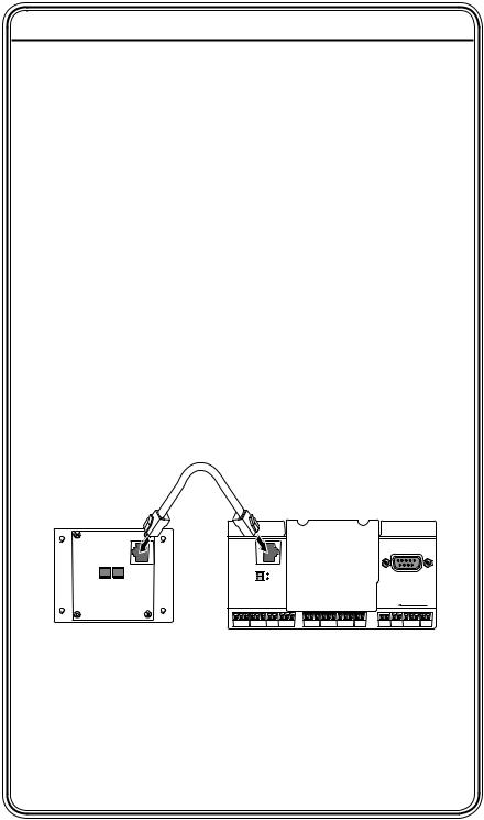
About the IP Intercom Modules
The Extron MediaLink IPI 104 AAP and IPI 204 are four-button IP intercom modules and the IPI 101 AAP and IPI 201 are one-button IP intercom modules for use with Extron’s two-way IP Intercom System. The IP Intercom System facilitates room-to- help desk or room-to-room communications within a building, a group of buildings, or even greater distances as long as the intercoms are part of the same network. It provides enhanced support using a standard local area or wide area IP network. For an IP Intercom System, each room requires an IPI 201 or IPI 204 intercom, or an MLC 226 IP MediaLink Controller connected to an IPI 104 AAP or IPI 101 AAP.
1-2 IPI 100 Series, IPI 200 Series • Introduction

NThe IPI 201 and IPI 204 are stand-alone units that do not require a connection to a MediaLink controller.
MediaLink IP Intercom HelpDesk software is installed on a central office or help desk PC to configure and manage IP Intercom System operations.
Connections between the IPI 101 AAP and IPI 104 AAP intercoms with MLC 226 IP and the network are via existing network drops using standard CAT 5, CAT 5e, or CAT 6 cables.
The Windows®-based MediaLink IP Intercom HelpDesk software makes it easy to set up, manage, and monitor the
IP Intercom System. The software also provides the ability for
•faster call response by any available help desk in the system
•enhanced staff utilization by consolidation of monitoring operations
•secure administrator configuration and operator log-in
•making announcements to all intercoms simultaneously
With the paging feature, the help desk operator can page a single room or group of rooms simultaneously. A line level output is available on the back on each MediaLink controller and stand-alone IPI model to mix into a local sound system in each room.
The IP Intercom enables real-time audio monitoring by the help desk for any room where an IPI is installed. Using the IP Intercom HelpDesk software, intercom calls and pages can be logged and dateand time-stamped on the help desk computer. Event logs can be accessed and archived for record keeping and tracking purposes.
In addition to the status monitoring capabilities built into the MLC 226 IP, the IP Intercom makes it possible to monitor audio for each room. For example, if a projector is disconnected from the MLC 226 IP serial port, the GlobalViewer software can be configured to automatically notify a help desk operator or security personnel via e-mail. For immediate notification, e-mails can be sent to multiple addresses including cell phones and wireless PDAs. Help desk operators or other authorized personnel can then use the IP Intercom’s audio monitoring capability to listen to the activity in this room, helping them determine if security personnel should be dispatched to investigate.
NIn some states it is illegal to listen in on rooms. To satisfy legal and privacy requirements, the intercom can play a recurring tone during room monitoring. This tone can be turned on or off in the HelpDesk Preferences.
IPI 100 Series, IPI 200 Series • Introduction |
1-3 |
Introduction, cont’d
Features
•Two-way, half-duplex voice communications over an IP network
•Compatibility with IP Intercom-enabled MLC 226 IP MediaLink Controllers (IPI 101 AAP and IPI 104 AAP)
•Backlit, configurable Push To Talk buttons
•Integrated speaker and microphone
•Three-position switch to adjust speaker volume levels (IPI 101 AAP and IPI 104 AAP only)
•LED indicator to show when the room is being monitored
•Four space and 2-gang Architectural Adapter Plate (AAP) opening mounting
•Connection via existing network cable drops (one drop per MLC-IPI pair, IPI 101 AAPs and IPI 104 AAPs, only)
System Requirements
The IP Intercom HelpDesk software is available at no charge via the Extron Web site (http://www.extron.com) or the CD that comes with your IPI. To install and run IP HelpDesk, you need a PC with the following things installed:
•Windows 2000 or Windows XP Professional
•Pentium 4, 2 GHz or faster microprocessor
•500 MB RAM, recommended (256 MB minimum)
•50 MB or more available hard disk space
•Windows-supported sound card, microphone, and speakers
•Microsoft Direct X version 9.0c or later
•Microsoft .NET framework, version 2.0 or later
•network card and a network connection
INTERCOM  MIC ON INTERCOM
  MIC ON
PUSH TO TALK
HELP |
ROOM |
LAB |
ADMIN |
|
PUSH TO |
HELP |
DESK |
101 |
|
OFFICE |
|
TALK |
DESK |
1 |
2 |
3 |
4 |
|
|
|
CONFIG |
|
|
IPI 204 |
CONFIG |
|
IPI 201 |
INTERCOM |
|
|
|
INTERCOM |
|
|
|
|
|
MIC ON |
|
|
MIC ON |
|
|
|
|
|
|
|
|
PUSH TO TALK |
|
|
|
|
|
HELP |
ROOM |
LAB |
ADMIN |
|
PUSH TO |
HELP |
DESK |
101 |
OFFICE |
|
TALK |
DESK |
|
|
|
|||||
1 |
2 |
3 |
4 |
|
|
|
CONFIG |
|
|
IPI 204 |
CONFIG |
|
|
|
|
|
|
|
||
Extron |
|
|
IPI 204 |
Extron |
|
IPI 201 |
1-4 IPI 100 Series, IPI 200 Series • Introduction

IPI 100 Series, IPI 200 Series
Chapter2Two
Installation
UL Requirements
Installing or Replacing Button Labels
Mounting the IPI 101 or IPI 104 into an AAP Wall Plate or Device Faceplate
Mounting the IPI 201 or IPI 204 into an AAP Wall Plate or Device Faceplate
IPI Rear Panel Features and Cabling
MLC Audio Connection
Sample Applications
Installation
WInstallation and service must be performed by authorized personnel only. This product should be used with a UL approved electrical box. See “UL Requirements”, below.
NThe MLC 226 IP to which the IPI intercom is connected must have been shipped after November 16, 2005 and also have firmware version 1.05 or later to support the IPI. To set up the IPI you must use the IPI Intercom HelpDesk. software.
UL Requirements
1.This unit is not to be connected to a centralized DC power source or used beyond its rated voltage range.
2.The IPI 100 AAPs or IPI 200 AAPs must be installed in a 2-gang UL listed junction box.
The UL approved electrical wall box (junction box) is not included with the IPI; the installer is responsible for obtaining and installing the box.
3.The unit must be installed in accordance with the National Electrical Code and with local electrical codes.
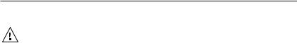
Installing or Replacing Button Labels
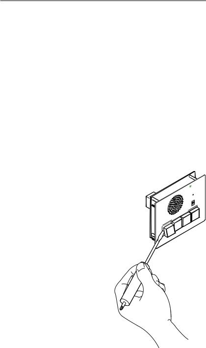
The button assembly consists of a clear lens cap, the label and a
white diffuser. To remove a button assembly and replace a label:
1. Use a small flat-blade screwdriver to gently pry the button assembly away from its plunger/base.
|
ON |
|
MIC |
|
LEVEL |
INTERCOM |
HIGH |
MED |
|
|
LOW |
|
ADMINE |
|
OFFIC |
LAB
SECURITY
HELP
DESK
104
2-2 IPI 100 Series, IPI 200 Series • Installation
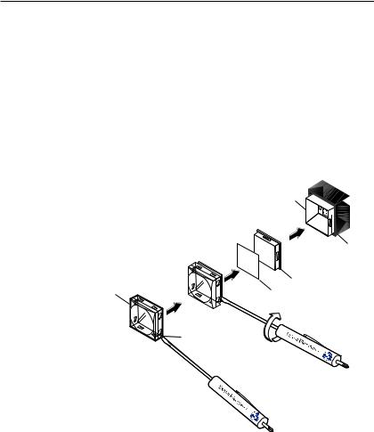
2.Locate the small corner notch on the lens cap and slide
the screwdriver between the lens cap and the diffuser, as shown in Ç.
Using a rotating motion of the screwdriver (see É), carefully pry the two pieces apart.
3.Replace the label with the new button label.
4.Press the lens cap and diffuser together and reinstall the button assembly into its plunger/base.
5.Repeat steps 1 through 4 for each button you plan to relabel.
|
|
Plunger |
|
|
|
TEXT |
|
Clear Lens |
É |
Diffuser |
|
Button Label |
|||
|
Pry Ç pieces
Notch
Separating the piece button the corner.
Base
IPI 100 Series, IPI 200 Series • Installation |
2-3 |
Installation, cont’d
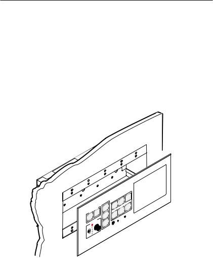
Mounting the IPI 101 or IPI 104 into an AAP Wall Plate or Device Faceplate
The IPI intercom and any other adapter plates must be attached to a device faceplate or AAP wall plate and cabled before the device or wall plate is installed in a wall or furniture. The screws needed for installing the IPI are built into its front panel.
1.Before cables are attached, insert the IPI’s screws through the holes in the device’s faceplate or AAP mounting frame. Secure the intercom module to the faceplate/wall plate with the provided captive washers and #4-40 nuts, as shown below:
#4-40 Nut w/ Captive
Washer
(included)
|
|
|
|
|
AUX |
|
|
|
|
|
VIDEO |
|
|
|
|
DVD |
|
|
|
AUTO |
VCR |
|
PC |
|
|
|
|
||
|
|
IMAGE |
|
DOC |
|
|
|
|
|
CA |
M |
|
OFF |
E |
OP |
|
|
ON |
|
MUT |
LAPT |
CONFIG |
|
|
|
|
|||
|
|
|
IR |
|
|
|
on |
Ex |
tr |
|
Extron
MLC 226 IP AAP
MediaLink Controller
IP |
AAP |
226 MLC
|
ON |
|
|
|
MIC |
|
|
|
LEVELHIG |
H |
|
M |
MED |
|
|
INTERCO |
LOW |
|
|
|
ADMINCE |
|
|
|
OFFI |
|
4 |
LAB |
|
10 |
|
|
|
||
TY |
|
|
|
SECURI |
|
|
|
HELP |
|
|
|
DESK |
|
|
|
IPI 104 AAP
Intercom
2.Connect each IPI to an MLC via the RJ-45 intercom ports on both devices using a standard CAT 5, CAT 5e, or CAT 6 straight through network cable. See “IPI Rear Panel Features and Cabling” on page 2-6.
3.Mount the AAP mounting frame or other device to the wall, furniture, or rack panel. Follow any special mounting instructions that came with that device.
2-4 IPI 100 AAP, IPI 200 AAP Series • Installation
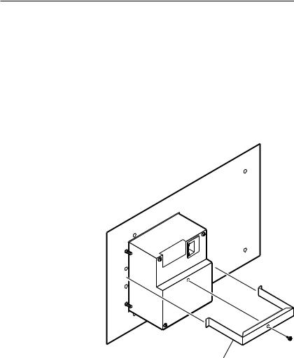
Mounting the IPI 201 or IPI 204 into an AAP Wall Plate or Device Faceplate
The IPI 201 and IPI 204 intercoms must be attached to a device faceplate or AAP wall plate and cabled before the device or wall plate is installed in a wall or furniture. Unlike the IPI 100 Series intercoms, the IPI 200 AAP Series intercoms are secured by attaching a clamp bracket to the back of the intercom after it has been inserted through the front of the AAP plate.
1.Before cables are attached, insert the IPI through the front of the device’s faceplate or AAP mounting frame. Secure the IPI to the faceplate/wall plate by attaching the provided clamp bracket.
Extron
IPI 204 AAP
Intercom
(rear view) Clamp Bracket (included)
2. Connect cables to the IPI. See “IPI Rear Panel Features and Cabling” on page 2-6.
3. Mount the AAP mounting frame or other device to the wall, furniture, or rack panel. Follow any special mounting instructions that came with that device.
IPI 100 AAP, IPI 200 AAP Series • Installation |
2-5 |
Installation, cont’d
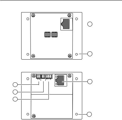
IPI Rear Panel Features and Cabling
IPI 104 AAP, IPI 101 AAP
Rear Panel
C NO
POWER RELAY AUDIO OUT
Power 3
LAN
Contact
Relay 4
Audio Out 5
 1a Intercom Port
2 AAP Mounting Screws (4)
1b LAN Port
2 AAP Mounting Screws (4)
IPI 204 AAP, IPI 201 AAP
Rear Panel
ÄIntercom port (IPI 101 AAP and IPI 104 AAP only) — This port is used for power, control, and voice data communication with the MLC. Plug one end of a standard, straight through, CAT 5, CAT 5e, or CAT 6 cable terminated with RJ 45 connectors into this port. Plug the other end of the cable into the Intercom connector on the MLC 226 IP’s rear panel, as shown in the following figure.
NA 12” (30.5 cm) CAT 6 cable is included with each IPI. If you choose to terminate your own cable, the cable must be no longer than 100’ (30.4 m).
Cables must be terminated to the T586A or T586B standard and both ends of a cable must be wired to the same standard.
2-6 IPI 100 AAP, IPI 200 AAP Series • Installation
R |
INTERCOM |
|
AUDIO OUT |
HOST
CONTROL
1=DIGITAL I/O 2=Tx 3=Rx 5=GND 38400, N, 8, 1
LAN |
PRESS TAB WITH |
TWEEKER TO REMOVE |
IPI 101 AAP or IPI 104 AAP |
MLC 226 IP Rear Panel |
Rear Panel |
|
ÅLAN port (IPI 201 AAP and 204 AAP only) — Plug an RJ-45 jack into the LAN connector to connect to a network. The blinking yellow LED indicates LAN activity. The green LED lights to indicate a good LAN connection.
Patch (straight-through) cable |
|
Crossover cable |
Side |
Clip Down |
|||||
|
Side 1 |
|
Side 2 |
|
Side 1 |
|
Side 2 |
12345678 Pins |
|
|
|
|
|
|
|||||
Pin |
Wire color |
Pin |
Wire color |
Pin |
Wire color |
Pin |
Wire color |
|
RJ-45 |
1 |
White-orange |
1 |
White-orange |
|
|
|
|
|
connector |
1 |
White-orange |
1 |
White-green |
|
|
||||
2 |
Orange |
2 |
Orange |
2 |
Orange |
2 |
Green |
|
|
3 |
White-green |
3 |
White-green |
3 |
White-green |
3 |
White-orange |
|
|
4 |
Blue |
4 |
Blue |
4 |
Blue |
4 |
Blue |
|
|
5 |
White-blue |
5 |
White-blue |
5 |
White-blue |
5 |
White-blue |
|
12345678 |
|
|
||||||||
6 |
Green |
6 |
Green |
6 |
Green |
6 |
Orange |
|
|
7 |
White-brown |
7 |
White-brown |
7 |
White-brown |
7 |
White-brown |
|
Twisted |
8 |
Brown |
8 |
Brown |
8 |
Brown |
8 |
Brown |
|
|
|
Pairs |
||||||||
|
|
|
|
|
|
|
|
1&2 |
7&8 |
|
|
|
|
|
|
|
|
|
3&6 4&5 |
|
B AAP mounting screws — These four screws are permanently |
||||||||
attached to the IPI’s faceplate. They are used for mounting the faceplate into another device (such as an MLC 226 IP AAP) or a mounting frame.
|
N Steps C to E apply to the IPI 201 and IPI 204 models. |
C |
Power — Connect a cable between the 2-pole, 3.5,mm captive |
|
screw connector and a 12 VDC, 2 A power supply (included). |
D |
Contact Relay — The contact relay connector is used to control |
|
items such as room lighting, window coverings, and door locks. |
|
The contact may be used to control any equipment as long as the |
|
contact specifications of 24 VDC at 1 A are not exceeded. |
IPI 100 AAP, IPI 200 AAP Series • Installation |
2-7 |
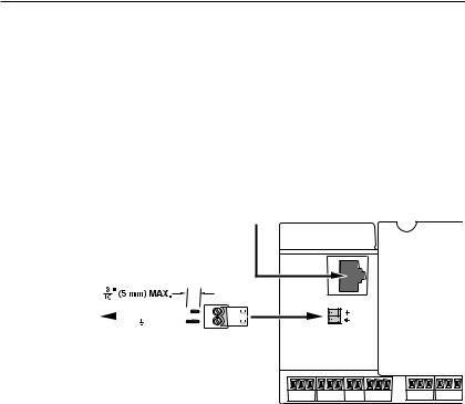
Installation, cont’d
E Audio Out — A 3-pole, 3.5 mm captive screw connector is used for audio output connection. It provides a -10 dBV unbalanced signal that can be connected to local, powered speakers or to any audio or paging system.
MLC Audio Connection
The MLC 226 IP Series controllers that support IPI intercom panels also have a rear panel, line level audio output port that can be connected to local, powered speakers or to any audio or paging system. See the wiring guide in the illustration below.
To/from the IPI 104 AAP or IPI 101 AAP 
Rear Panel Intercom Port
To a Speaker, |
+ |
|
|
|
|
|
|||
Audio System, or |
|
|
|
|
|
|
|
|
|
|
|
|
|
|
|
|
|
|
|
Paging System |
|
|
|
|
|
|
|
|
|
Captive Screw
Connector
Do not tin the wires!
MLC 226 IP Rear Panel
R |
INTERCOM |
AUDIO
OUT
NThe volume for this audio output can be adjusted via software only.
Sample Applications
There are several ways to make use of an IP Intercom System. To see what you can do with the IPIs, look at the sample scenarios provided in this section.
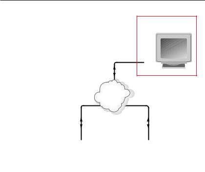
Single PC-to-panel mode
For a simple intercom system, connect one or more panels to a PC that serves as the help desk console.
1.Connect one or more IPI 201, IPI 204 units, or MLC 226 IP(s) with one or more IPI 101 AAP and/or IPI 104 AAP units to a network using straight-through cable.
2.Using a PC in the same network, configure the IPI systems, assigning the PC’s IP address to one button on each IPI (see chapter 4 ). The button light changes from red tolow amber to indicate it is configured and connected to the PC.
2-8 IPI 100 AAP, IPI 200 AAP Series • Installation
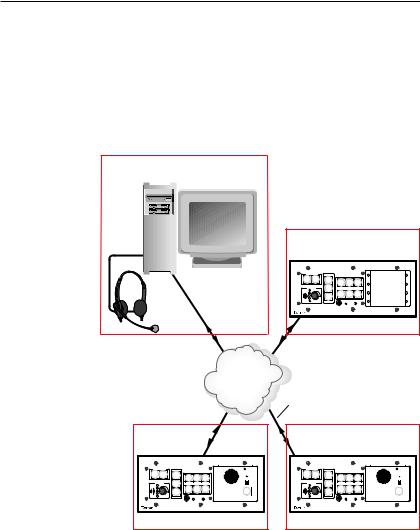
3.The intercom user presses and holds the button assigned to the PC to initiate talk mode. The button glows bright amber, and the Mic On LED lights.
4.The user speaks into the intercom. Audio is output through the PC speakers at the help desk console.
5.The intercom user releases the button when done speaking.
6.The console operator clicks the Talk button (in the software) or presses the PC’s space bar to respond.
Help Desk Console
IP 10.XX.XX.01
Audio
Card
Office
IP 10.XX.XX.04
PROJECTOR |
|
|
|
INTERCOM |
MIC ON |
|
ON |
OFF |
AUTO |
|
|
|
|
|
|
IMAGE |
VCR |
DVD |
AUX |
|
|
|
|
VIDEO |
LEVEL |
||
VOLUME MUTE
|
|
|
PUSH TO TALK |
|
|
LAPTOP |
PC |
HELP |
SECURITY |
LAB |
ADMIN |
|
|
DESK |
OFFICE |
||
|
|
1 |
2 |
3 |
4 |
IPI 104
MLC 226 IP
IPI 104 AAP
TCP/IP
Network Straight-through
Network Cable
Classroom |
|
|
|
|
|
|
|
Lab |
|
IP 10.XX.XX.02 |
|
|
|
IP 10.XX.XX.03 |
|||||
PROJECTOR |
|
|
INTERCOM |
MIC ON |
PROJECTOR |
|
|
INTERCOM |
MIC ON |
ON OFF AUTO |
|
|
|
|
ON OFF AUTO |
|
|
|
|
IMAGE |
VCR |
DVD |
AUX |
|
IMAGE |
VCR |
DVD |
AUX |
|
|
VIDEO |
LEVEL |
|
VIDEO |
LEVEL |
||||
VOLUME |
MUTE |
|
|
|
VOLUME |
MUTE |
|
|
|
|
LAPTOP |
PC |
PUSH TO |
HELP |
|
LAPTOP |
PC |
PUSH TO |
HELP |
|
|
|
TALK |
DESK |
|
|
|
TALK |
DESK |
|
|
|
|
IPI 101 |
|
|
|
|
IPI 101 |
MLC 226 IP |
MLC 226 IP |
MLC 226 IP AAP IPI 101 AAP |
MLC 226 IP AAP IPI 101 AAP |
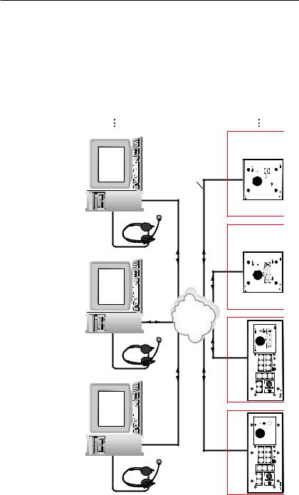
Multiple PC-to-panel mode
Some facilities may require a system with two or more console PCs. One may be staffed by a computer applications expert, another by security personnel, and a third by resource aides or lab stockroom staff. Each console is configured to connect with several intercoms, and each intercom is configured to contact up to four consoles.
1.Connect up to a maximum of 125 intercoms (per help desk PC) to a network using straight-through cable.
IPI 100 AAP, IPI 200 AAP Series • Installation |
2-9 |
Installation, cont’d
2.Connect one or more PCs to the same network and install the IP Intercom HelpDesk Software on each PC.
Read chapter 4 for instructions on how to install and use the software.
4 Consoles (max.) |
50 Intercoms (max.) |
Chem Lab Stockroom |
Straight-through |
Network Cable |
Office |
IP 10.XX.XX.07 |
IP 10.XX.XX.03 |
Audio Card |
Lab 10.XX.XX.06 |
|
|
IP |
|
Campus |
Police |
IP 10.XX.XX.02 |
MIS |
DeskHelp |
TCP/IP Network |
Classroom |
10.XX.XX.05IP |
PROJECTOR |
ON OFF IMAGE |
VOLUME |
LAPTOP PC |
IP226MLC |
|
|
Audio |
Card |
|
|
|
|
|
VCR DVD |
|
|
|
|
|
|
|
|
|
|
|
AUX VIDEO |
|
|
|
|
|
|
|
|
|
|
|
AUTO |
MUTE |
|
|
|
|
|
|
|
|
|
|
|
|
PUSH TO TALK |
|
10.XX.XX.01IP |
Audio |
Card |
|
|
Classroom |
10.XX.XX.04IP |
PROJECTOR |
AUX VIDEO |
VOLUME |
PC |
|
|
|
OFFON IMAGE |
LAPTOP |
|
|||||||
|
|
|
|
|
|
|
|
DVD |
|
|
|
|
|
|
|
|
|
|
|
VCR |
|
|
|
|
|
|
|
|
|
|
|
AUTO |
MUTE |
|
|
2-10 IPI 100 Series, IPI 200 Series • Installation

3.Configure the intercoms and set up the intercom list for each console PC. Each console could be set up to monitor a different group of intercoms, but most likely the lists will overlap.
In this example, an installation in one building of a college campus, each room (classroom, lab, or office) contains
an intercom. Configure one button on each intercom to contact the computer help desk, and another button on each intercom to contact the campus security department. However, only the intercoms located in physical sciences classrooms and laboratories have a third button configured to contact the PC console in the lab stockroom. Only the intercoms installed in offices have a button configured to call the registration department’s console.
4.Once the system is configured, each intercom user presses and holds a button to initiate talk mode. The button glows bright amber, and the Monitor LED lights.
5.The user speaks into the intercom. Audio plays through the speakers or headset at the console the pressed button was configured to call.
6.The intercom user releases the button when done speaking.
7.The console operator clicks the Talk button (in the software) or presses the PC’s space bar to reply.
Panel-to-panel mode
You do not need to include a console PC as a permanent part of an IP Intercom System. Here is an example in which panels are configured to “talk” to each other. The software does not need to be running during intercom system operation.
NPanel to panel mode will only work when both panels are in the same network subnet.
1.Connect two IPI 101 AAPs and their MLC 226 IPs to a network using straight-through cable.
2.Using a PC connected to the same network (as shown in the following figure), configure the two IPI systems. Read chapter 4 for instructions on how to use the software for configuration.
3.Close the configuration program. The PC can be disconnected from the network or used for other functions.
4.Push the button on one IPI to contact the other IPI. On the calling IPI, the microphone is enabled, the Mic On LED lights, and the button’s light changes from low amber to bright/high amber. On the IPI being called, the button’s light changes from low amber to bright/high amber.
IPI 100 Series, IPI 200 Series • Installation |
2-11 |
Installation, cont’d
Connect for configuration. This connection is not needed for later operation.
Configuration Console PC |
IP 10.XX.XX.01 |
TCP/IP
Network Straight-through
Network Cable
Classroom |
Lab |
IP 10.XX.XX.02 |
IP 10.XX.XX.03 |
PROJECTOR |
|
|
|
|
INTERCOM |
MIC ON |
PROJECTOR |
|
|
|
|
INTERCOM |
MIC ON |
||
ON |
OFF |
AUTO |
|
|
|
|
|
ON |
OFF |
AUTO |
|
|
|
|
|
|
|
IMAGE |
VCR |
DVD |
AUX |
|
|
|
|
IMAGE |
VCR |
DVD |
AUX |
|
|
|
|
|
VIDEO |
|
LEVEL |
|
|
|
VIDEO |
|
LEVEL |
||||
VOLUME |
MUTE |
|
|
|
|
|
VOLUME |
MUTE |
|
|
|
|
|
||
|
|
|
LAPTOP |
|
PC |
PUSH TO |
HELP |
|
|
|
LAPTOP |
|
PC |
PUSH TO |
HELP |
|
|
|
|
|
|
TALK |
DESK |
|
|
|
|
|
|
TALK |
DESK |
|
|
|
|
|
|
|
IPI 101 |
|
|
|
|
|
|
|
IPI 101 |
MLC 226 IP |
MLC 226 IP |
MLC 226 IP AAP IPI 101 AAP |
MLC 226 IP AAP IPI 101 AAP |
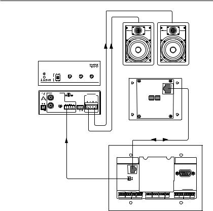
Intercom with amplifier mode
The MLC’s Audio Out 2-pole captive screw connector outputs a -10 dBV audio signal that can be routed to an MPA 122 or any external audio amplifier, then to speakers.
1.Cable the system as shown in the following diagram.
2.Power on the equipment.
3.Make fine adjustments to output level using the Remote Line slider in the Advanced Settings part of the HelpDesk software. The external amplifier (the MPA 122 in this example) must be adjusted properly to avoid any audio signal clipping or audio distortion.
4.If desired, use the software to adjust to minimum levels the MLC’s audio output, the IPI’s speaker output, or both.
2-12 IPI 100 AAP, IPI 200 AAP Series • Installation
ON |
STEREO LEVEL |
BASS |
TREBLE |
LIMITER
OFF |
MONO |
|
MPA 122 |
|
DUAL |
|
|
|
|
|
MINI POWER AMPLIFIER |
INPUTS |
|
|
MPA 122 |
|
C |
US |
OUTPUTS |
|
|
|
4/8 Ohms |
POWER |
|
|
REMOTE |
|
|
|
|
|
|
|
|
12V |
L |
R |
10V |
L |
R |
3A MAX |
|
|
VOL/MUTE |
|
|
MPA 122
SI 26W
IPI 104 AAP, IPI 101 AAP
Rear Panel
R |
INTERCOM |
HOST |
CONTROL |
||
|
||
|
AUDIO OUT |
1=DITIGAL I/O |
|
2=Tx 3=Rx 5=GND |
|
|
|
38400, N, 8, 1 |
|
LAN |
PRESS TAB WITH |
|
TWEEKER TO REMOVE |
MLC 226 IP
IPI 100 Series, IPI 200 Series • Installation 2-13

Installation, cont’d
2-14 IPI 100 AAP, IPI 200 AAP Series • Installation

IPI 100 Series, IPI 200 Series
Chapter3Three
Operation
Front Panel Features and Operation
Button Operation

Operation
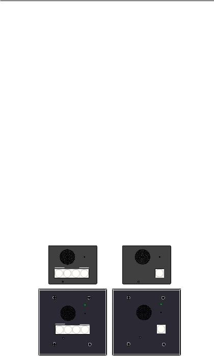
Front Panel Features and Operation
A B
C D
Speaker — This integrated speaker provides mono output at the IPI panel.
Mic On LED — This LED lights under two circumstances:
•When a configured Push to Talk button is pressed.
•To indicate that someone at the help desk console is listening and that the intercom is in monitoring mode. Monitoring mode permits hands-free operation: the user does not have to press the Push to Talk button to speak into the intercom. It also lets help desk staff monitor what is happening to determine whether to send security personnel to that room.
Microphone — Speak into the microphone, which is behind this opening.
Level switch — This three-position switch lets |
LEVEL |
||
|
|
HIGH |
|
you change the speaker’s loudness level (IPI 100 |
|
|
MED |
|
|
||
series, only). |
|
|
LOW |
|
|
||
|
|
||
3-2 IPI 100 Series, IPI 200 Series • Operation
Loading...