


 Loading...
User Guide
SCALERS AND SIGNAL PROCESSORS
DVS 605
HDCP-Compliant Scaler
(with Seamless Switching)
DVS 605
DVS 605 AD
68-2110-01 Rev. B
05 13
Safety Instructions
Safety Instructions • English
WARNING: This symbol, |
, when used on the product, is intended |
to alert the user of the presence of uninsulated dangerous voltage |
|
within the product’s enclosure that may present a risk of electric |
|
shock. |
|
ATTENTION: This symbol,  , when used on the product, is intended to alert the user of important operating and maintenance (servicing) instructions in the literature provided with the equipment.
For information on safety guidelines, regulatory compliances, EMI/EMF compatibility, accessibility, and related topics, see the Extron Safety and Regulatory Compliance Guide, part number 68-290-01, on the Extron website, www.extron.com.
Instructions de sécurité • Français |
|
avertissement: Ce pictogramme, |
, lorsqu’il est utilisé sur le |
produit, signale à l’utilisateur la présence à l’intérieur du boîtier |
|
du produit d’une tension électrique dangereuse susceptible de |
|
provoquer un choc électrique. |
|
ATTENTION: Ce pictogramme,  , lorsqu’il est utilisé sur le produit, signale à l’utilisateur des instructions d’utilisation ou de maintenance importantes qui se trouvent dans la documentation fournie avec le matériel.
Pour en savoir plus sur les règles de sécurité, la conformité à la réglementation, la compatibilité EMI/EMF, l’accessibilité, et autres sujets connexes, lisez les informations de sécurité et de conformité Extron, réf. 68-290-01, sur le site Extron, www.extron.fr.
Sicherheitsanweisungen • Deutsch
WARNUNG: |
Dieses Symbol |
auf dem Produkt soll den |
Benutzer darauf aufmerksam machen, dass im Inneren des |
||
Gehäuses dieses Produktes gefährliche Spannungen herrschen, |
||
die nicht isoliert sind und die einen elektrischen Schlag |
||
verursachen können. |
|
|
VORSICHT: Dieses Symbol  auf dem Produkt soll dem Benutzer in der im Lieferumfang enthaltenen Dokumentation besonders wichtige Hinweise zur Bedienung und Wartung (Instandhaltung) geben.
Weitere Informationen über die Sicherheitsrichtlinien, Produkthandhabung, EMI/EMF-Kompatibilität, Zugänglichkeit und verwandte Themen finden Sie in den Extron-Richtlinien für Sicherheit und Handhabung (Artikelnummer 68-290-01) auf der Extron-Website, www.extron.de.
Instrucciones de seguridad • Español
ADVERTENCIA: |
Este símbolo, |
, cuando se utiliza en el producto, |
avisa al usuario de la presencia de voltaje peligroso sin aislar dentro |
||
del producto, lo que puede representar un riesgo de descarga |
||
eléctrica. |
|
|
ATENCIÓN: Este símbolo,  , cuando se utiliza en el producto, avisa al usuario de la presencia de importantes instrucciones de uso y mantenimiento recogidas en la documentación proporcionada con el equipo.
Para obtener información sobre directrices de seguridad, cumplimiento de normativas, compatibilidad electromagnética, accesibilidad y temas relacionados, consulte la Guía de cumplimiento de normativas y seguridad de Extron, referencia 68-290-01, en el sitio Web de Extron, www.extron.es.
Chinese Simplified
|
|
 (
(
EMI/EMFExtron www.extron.cn Extron68-290-01
Chinese Traditional
: 

EMI/EMFExtron www.extron.cn Extron
68-290-01
Japanese
: 
:  ( )
( )
EMI/EMFwww.extron.jp
Extron Safety and Regulatory Compliance Guide (P/N 68-290-01)
Korean
:  , , .
, , .
:  , ,( ) .
, , EMI/EMF , ,Extron (www.extron.co.kr) Extron , 68-290-01 .

FCC Class A Notice
This equipment has been tested and found to comply with the limits for a Class A digital device, pursuant to part 15 of the FCC rules. The Class A limits provide reasonable protection against harmful interference when the equipment is operated in a commercial environment. This equipment generates, uses, and can radiate radio frequency energy and, if not installed and used in accordance with the instruction manual, may cause harmful interference to radio communications. Operation of this equipment in a residential area is likely to cause interference; the user must correct the interference at his own expense.
NOTE: For more information on safety guidelines, regulatory compliances, EMI/EMF compatibility, accessibility, and related topics, see the “Extron Safety and Regulatory Compliance Guide” on the Extron website.
Copyright
© 2013 Extron Electronics. All rights reserved.
Trademarks
All trademarks mentioned in this guide are the properties of their respective owners.
The following registered trademarks(®), registered service marks(SM), and trademarks(TM) are the property of RGB Systems, Inc. or Extron Electronics:
Registered Trademarks (®)
AVTrac, Cable Cubby, CrossPoint, eBUS, EDID Manager, EDID Minder, Extron, Flat Field, GlobalViewer, Hideaway, Inline, IP Intercom, IP Link, Key Minder, LockIt, MediaLink, PoleVault, PowerCage, PURE3, Quantum, SoundField, SpeedSwitch, System Integrator, TeamWork, TouchLink, V Lock, VersaTools, VN Matrix, VoiceLift, WallVault, WindoWall
Registered Service Mark(SM) : S3 Service Support Solutions
Trademarks (™)
AAP, AFL (Accu Rate Frame Lock), ADSP (Advanced Digital Sync Processing), AIS (Advanced Instruction Set), Auto Image, CDRS (Class D Ripple Suppression), DDSP (Digital Display Sync Processing), DMI (Dynamic Motion Interpolation), Driver Configurator, DSP Configurator, DSVP (Digital Sync Validation Processing), FastBite, FOXBOX, IP Intercom HelpDesk, MAAP, MicroDigital, ProDSP, QS-FPC (QuickSwitch Front Panel Controller), Scope Trigger, SIS, Simple Instruction Set, Skew Free, SpeedMount, SpeedNav, Triple Action Switching, XTP, XTP Systems, XTRA, ZipCaddy, ZipClip
Conventions Used in this Guide
Notifications
The following notifications are used in this guide:
DANGER: A danger indicates a situation that will result in death or severe injury.
WARNING: A warning indicates a situation that has the potential to result in death or |
severe injury. |
CAUTION: A caution indicates a situation that may result in minor injury.
ATTENTION: Attention indicates a situation that may damage or destroy the product or associated equipment.
NOTE: A note draws attention to important information.
TIP: A tip provides a suggestion to make working with the application easier.
Software Commands
Commands are written in the fonts shown here:
^AR Merge Scene,,Op1 scene 1,1 ^B 51 ^W^C [01]R000400300004000080000600[02]35[17][03]
E X! *X1&* X2)* X2#* X2! CE}
NOTE: For commands and examples of computer or device responses mentioned in this guide, the character “0” is used for the number zero and “O” represents the capital letter “o.”
Computer responses and directory paths that do not have variables are written in the font shown here:
Reply from 208.132.180.48: bytes=32 times=2ms TTL=32 C:\Program Files\Extron
Variables are written in slanted form as shown here: ping xxx.xxx.xxx.xxx —t
SOH R Data STX Command ETB ETX
Selectable items, such as menu names, menu options, buttons, tabs, and field names are written in the font shown here:
From the File menu, select New. Click the OK button.
Specifications Availability
Product specifications are available on the Extron website, www.extron.com.

Contents
............................................................Introduction |
1 |
DVS 605 Series Description................................ |
1 |
Licensed Third-party Software Used in the DVS |
|
605.................................................................... |
2 |
Key Features....................................................... |
3 |
Video Inputs.................................................... |
3 |
Video Outputs................................................. |
3 |
Audio.............................................................. |
4 |
General........................................................... |
4 |
Controlling the DVS 605...................................... |
6 |
|
|
Rear Panel Connections...................................... |
7 |
Rear Panel Cabling.............................................. |
7 |
|
|
Operation.............................................................. |
12 |
Front Panel Overview........................................ |
12 |
Powering Up .................................................... |
13 |
The DVS 605 Menu System — Configuration and |
|
Adjustments..................................................... |
13 |
Menu Navigation Using Front Panel Controls. 13 |
|
Menu Overview............................................. |
14 |
User Presets................................................. |
16 |
Picture Control.............................................. |
16 |
Input Configuration........................................ |
17 |
Output Configuration..................................... |
18 |
Audio Configuration (All Models).................... |
22 |
Advanced Configuration................................ |
23 |
View Comm Settings..................................... |
26 |
Exit Menu...................................................... |
26 |
Front Panel Lockout (Executive Modes)............. |
27 |
Window vs. Image Size Position — An Overview28 |
|
Picture-in-picture (PIP) Mode............................. |
29 |
Front Panel Activation.................................... |
29 |
PIP Presets .................................................. |
30 |
Other DVS 605 Operating Features................... |
31 |
Screen Save.................................................. |
31 |
Power Save .................................................. |
31 |
Custom EDID/Custom Output Resolution...... |
31 |
The OSD Bug................................................ |
32 |
Hardwired IR Port.......................................... |
32 |
Resetting the Unit.............................................. |
33 |
SIS Communication and Control..................... |
34 |
Host to Scaler Communications........................ |
34 |
Scaler-initiated Messages.............................. |
34 |
Copyright Information.................................... |
34 |
Password Information.................................... |
35 |
Error Responses........................................... |
35 |
Error Response References........................... |
35 |
Commands and Responses.............................. |
35 |
Using the Command and Response Tables... |
35 |
Symbol Definitions......................................... |
36 |
SIS Command and Response Table.................. |
42 |
SIS Command and Response Table for IP |
|
Control Port................................................. |
56 |
Using the Default Web Pages ......................... |
61 |
Accessing the Default Web Pages..................... |
61 |
Turning Off Compatibility Mode...................... |
62 |
Navigating the Default Web Pages.................... |
62 |
Configuration Pages.......................................... |
63 |
AV Controls Panel ........................................ |
63 |
Input/Output Configuration Page — Input |
|
Configuration Panel...................................... |
65 |
Input/Output Configuration Page — Output |
|
Configuration Panel...................................... |
67 |
EDID Minder Page......................................... |
69 |
Image Settings Page..................................... |
71 |
PIP Settings Page......................................... |
74 |
Audio Settings Page...................................... |
77 |
Preset Management Page............................. |
79 |
Device Settings Page.................................... |
80 |
Hardware Pages............................................... |
83 |
Unit Information Page.................................... |
83 |
Device Name Page........................................ |
84 |
Connection Settings Page............................. |
84 |
Firmware Loader Page.................................. |
85 |
Executive/Power Mode Page........................ |
86 |
Date and Time Page..................................... |
87 |
Password Page............................................. |
88 |
DVS 605 • Contents |
v |

Mounting............................................................... |
90 |
Mounting the DVS 605...................................... |
90 |
Tabletop Placement....................................... |
90 |
UL Guidelines for Rack Mounted Devices ..... |
90 |
Rack Mounting.............................................. |
91 |
Furniture Mounting........................................ |
91 |
Warranty................................................................ |
92 |
Contact Information........................................... |
92 |
DVS 605 • Contents |
vi |

Introduction
This manual contains information about the Extron DVS 605 scalers with instructions for experienced installers on how to install, configure, and operate the equipment.
In this manual the terms “DVS,” “digital video scaler,” and “scaler” are used interchangeably and refer to any DVS 605 model.
DVS 605 Series Description
The DVS 605 series of digital video scalers is comprised of:
•DVS 605, standard model
•DVS 605 A, with audio switching
•DVS 605 D, with 3G/HD-SDI output
•DVS 605 AD, with 3G/HD-SDI output and audio switching
All models are full rack width, and are available with optional 3G/HD-SDI outputs (DVS 605 D and DVS 605 AD) and balanced/unbalanced audio (DVS 605 A and DVS 605 AD).
All models are high performance video scalers that include three HDMI inputs, two universal analog video inputs, and simultaneous HDMI and analog high resolution outputs. The DVS 605 models accept a wide variety of video formats including HDMI with HDCP, HDTV, RGB, and standard definition video. They feature advanced Extron video signal processing with 1080i de-interlacing, Deep Color processing, and true seamless switching for professional-quality presentations. The DVS 605 models offer flexible control options including Ethernet, RS-232, USB, hardwired IR, and contact closure.
The five inputs of all DVS 605 models accommodate a variety of sources. The analog inputs can automatically detect and process RGB computer-video, HDTV, component video, S-video, and composite video. The DVS 605 provides the capability to integrate digital and analog video devices, with HDCP compliance to enable integration of BluRay Disc players and cable or satellite HD receivers. Auto-switching between inputs streamlines system operation as well as integration with presentation switchers or matrix switchers.
Output scan rates are available from VGA (640x480) to 1920x1200 resolution, as well as HDTV at 720p, 1080i, 1080p/60 Hz, and 2k/60 Hz.
NOTE: See the Resolution and Refresh Rates table on page 18 for a complete |
list. |
The DVS 605 models feature EDID Minder and Key Minder. EDID Minder automatically manages Extended Digital Identification Data (EDID) communications between the display device and all the HDMI and VGA computer-video input sources.
For HDMI signals with protected content, Key Minder authenticates and maintains continuous HDCP encryption between input and output devices to ensure quick and reliable switching in professional AV environments.
DVS 605 models with audio switching feature HDMI audio embedding and de-embedding. Any input audio signal can be embedded onto the HDMI output. DVS 605 audio models can also extract embedded HDMI audio to analog and digital
S/PDIF outputs. The DVS 605 AD, with audio switching plus 3G-SDI/HD-SDI output, can embed up to eight channels of audio onto the SDI output.
DVS 605 • Introduction |
1 |
Licensed Third-party Software Used in the DVS 605
The DVS 605 uses various licensed third-party software during operation. To view details about third-party packages and associated licensing, click the License Information button on the Unit Information page of the Default web pages (see the Unit Information Page on page 82). The DVS 605 License Information
dialog box opens.
To view a copy of a listed package license, in the dialog box, click the link in the License column for the relevant package. This opens in a separate window a copy of the package license.
Click Close to close the dialog box.
The table below lists the licensed third-party software used by the DVS 605.
NOTE: Licensed third-party software used by the |
DVS 605 is subject to change without notice. |
Licensed Third-party Software Used in the DVS 605
Package |
License |
Package |
License |
|
|
|
|
avahi |
GNU LGPL v2.1 |
libpng |
libpng license |
|
|
|
|
bstrib |
BSD |
lighttpd |
BSD |
|
|
|
|
busybox |
GNU GPL v2 |
Linux |
GNU GPL v2 |
|
|
|
|
bzip2 |
BSD |
lua |
MIT |
|
|
|
|
cjson |
MIT |
lua-cjson |
MIT |
expat |
BSD |
luafilesystem |
MIT |
|
|
|
|
ExtJS4 |
Sencha Commercial License |
luasocket |
MIT |
fcgi |
fcgi |
luastruct |
MIT |
|
|
|
|
freetype |
Free Type License |
mtd |
GNU GPL v2 |
|
|
|
|
gnupg-1.4.7 |
GNU LGPL v2.1 |
ncurses |
MIT |
gpgme |
GNU LGPL |
openssh |
BSD |
|
|
|
|
ifplugd |
GNU GPL |
openssl |
OpenSSL |
|
|
|
|
jpeg |
libjpeg |
PAM |
BSD |
libassuan |
GNU LGPL |
pcre |
BSD |
|
|
|
|
libcgicc 3.2.3 |
GNU LGPL v2.1 |
psmisc |
GNU GPL v2 |
|
|
|
|
libcurl |
ICS |
qt |
GNU LGPL v2.1 |
libdaemon |
GNU GPL v2.1 |
socat |
GNU GPL v2 |
|
|
|
|
libdnet |
BSD |
spawn-fcgi |
BSD |
|
|
|
|
libgpg |
GNU GPL v2.1 |
sqlite |
Public Domain |
|
|
|
|
libcap |
BSD |
xinetd |
Custom |
|
|
|
|
net-snmp |
BSD |
|
|
|
|
|
|
DVS 605 • Introduction |
2 |

Key Features
Video Inputs
•Three HDMI and two universal analog video inputs — The two universal 15-pin HD inputs automatically detect incoming RGB, HD component video, YUVi, S-video, or composite video signals. The DVS 605 allows for seamless switching between HDMI and analog video sources.
•Auto input format detection — For the universal analog video inputs, the DVS 605 detects the incoming signal format, automatically reconfiguring the scaler to provide the appropriate decoding and signal processing.
•Auto-switching between inputs — The DVS 605 can automatically switch between input sources. The unit can be set up to automatically switch to an active input, by giving priority to the highest active input (51), or to the lowest active input (15). This allows for simple, automated control of the DVS 605 when a control system is not in use.
Auto Switch feature detects “active” video inputs by the presence of valid Horizontal and Vertical sync inputs, and not by the presence of an input cable, or +5 VDC from a source that is currently not outputting active video. Using simultaneous video input detection on all inputs, the DVS 605 will switch to the active input depending on the configured order of precedence (highlow vs. lowhigh).
With auto-switching, the DVS 605 can accommodate additional inputs when connected to the outputs of a larger presentation switcher, or can be used for unmanaged switching, or as an upstream matrix switcher.
NOTE: When Auto Switch mode is active, PIP mode cannot be enabled. Similarly, |
if PIP mode is currently active, Auto Switch mode cannot be enabled. |
•True seamless switching — Seamless cut and dissolve transition effects are available for inputs 1 to 4. Input 5 features glitch-free switching with a fade through to black.
Video Outputs
•3G/HD-SDI output — Active only if the current resolution is set to 720p, 1080i, 1080p, or 2k 23.98/24/25 Hz. All video outputs (HDMI, VGA, SDI) share a common output resolution and display the same content.
•Simultaneous scaled outputs for HDMI, HD-SDI, and analog RGB or HD component video — HDMI and high resolution analog RGB or component video outputs are available for driving two displays.
•Selectable output rates — Available output rates include computer video (640x480 ) up to 1920x1200, HDTV rates up to 1080p/60 Hz, and 2048x1080 (2k/60 Hz).
•Picture-in-picture (PIP) — For inputs 1 to 4, the DVS 605 provides unrestricted two-window display of standard definition and high resolution digital and analog video sources. Multiple PIP presets are available, including side-by-side windows. The main and PIP windows can be dynamically sized, positioned, and magnified. In audio models, audio switching can be set to follow either the main or PIP window.
DVS 605 • Introduction |
3 |

Audio
•Audio switching — The DVS 605 A and DVS 605 AD feature audio switching for five analog stereo balanced or unbalanced inputs.
•Output volume control — DVS 605 audio models provide master volume control. Fixed and variable line level outputs are available, and each output can be balanced or unbalanced. Stereo input signals can be output as dual mono. The DVS 605 audio models also include a S/PDIF digital audio output.
•Audio input gain and attenuation — Gain or attenuation can be adjusted for each analog audio input to eliminate noticeable differences when switching between sources.
•Audio breakaway — Provides the capability to break an analog audio signal away from its corresponding video signal and route to the audio outputs, allowing the analog audio channels to be operated as a separate switcher.
•Audio switching transitions — A transition technique can be applied during switches that lowers the audio of the switched-out source while simultaneously bringing up the audio of the activated source. The duration of the audio crossfade matches the duration of the video switching transition.
•Integrated audio delay — The DVS automatically delays all analog and digital audio inputs to compensate for internal video processing delay. Occasionally additional audio delay is required to account for other signal processors, scalers, or display devices in a system. For these situations, the DVS 605 offers an additional 0-255 ms static global audio delay that can be set via SIS command or internal web pages to eliminate audio “lip sync” issues.
•HDMI audio embedding and de-embedding — For DVS 605 models with audio, analog input audio signals can be embedded onto the HDMI output signal.
The DVS 605 can also extract PCM embedded HDMI audio signals. Encoded bitstream audio for Dolby® Digital or DTS® Digital Surround a can be passed to the HDMI and S/PDIF outputs.
General
•HDCP compliance — features include data rates up to 6.75 Gbps, Deep Color, and HD lossless audio formats.
•HDCP authentication and signal presence confirmation — The DVS 605 provides real-time verification via RS-232 or Ethernet of the HDCP status for each digital video input and output. This allows for signal and HDCP verification through USB, RS-232, or Ethernet, providing feedback to a system operator or helpdesk support staff.
•HDCP visual confirmation — This provides a green signal when encrypted content is sent to a non-compliant display, providing immediate visual confirmation that protected content cannot be viewed on the display.
•Key Minder — This feature continuously verifies HDCP compliance for quick, reliable switching. It authenticates and maintains continuous HDCP encryption between input and output devices to ensure quick and reliable switching while enabling simultaneous distribution of a single source signal to one or more displays.
•Advanced scaling engine — The DVS 605 features a high performance 30-bit scaling engine with the ability to scale high resolution computer-video and HDTV as well as standard definition video up or down in resolution.
•EDID Minder — This feature automatically manages EDID communication between connected devices, ensuring all sources power up properly and reliably output content for display.
DVS 605 • Introduction |
4 |
•AFL - Accu-RATE Frame Lock — A patented technology exclusive to Extron that eliminates image tearing caused by frame rate conversion.
•Image freeze control — A live image can be frozen using control via USB, RS-232 serial, Ethernet, or IR control.
•Auto-Image setup — When activated, the unit automatically detects the resolution of the incoming video signal and sets the total pixels, active pixels, and active lines, as well as the horizontal and vertical starting points.
•Auto Input Memory — When activated, the DVS 605 automatically stores size, position, and picture settings based on the incoming signal. When the same signal is detected again, these image settings are automatically recalled from memory.
•On-screen display — The DVS 605 features an on-screen display that displays status information of the currently selected input.
•On-screen input labels — An on-screen text label may be assigned to each input. The label can be up to 16 characters and input via RS-232 or Ethernet.
•Power screen saver mode and standby modes — The DVS 605 can be set to automatically mute video and sync output to the display device when no active input signal is detected. This allows the projector or flat-panel display to automatically enter into standby mode to save energy and enhance lamp or panel life.
•Picture controls — These include brightness, contrast, color, tint, and detail, as well as horizontal and vertical positioning, and sizing. 16 user memory presets are available for each input to store all image settings.
•Automatic 3:2 and 2:2 pulldown detection — The DVS 605 offers advanced film mode processing techniques that help maximize image detail and sharpness for NTSC, PAL, and HDTV 1080i sources that originated from film.
•Motion adaptive 1080i and SD de-interlacing — The DVS 605 provides high performance de-interlacing for 1080i and standard definition signals from sources including cable or satellite set-top boxes, delivering optimized image quality through advanced motion compensation.
•Aspect ratio control — The aspect ratio of the video output can be controlled by selecting a Fill mode, which provides a full screen output, or a Follow mode, which preserves the original aspect ratio of the input signal.
•Quad standard video decoding — The DVS 605 uses a digital, 3D adaptive comb filter to decode NTSC 3.58, NTSC 4.43, PAL, and SECAM signals for integration into systems worldwide.
•Internal test patterns for calibration and setup — The DVS 605 offers 14 test patterns; crop pattern, crosshatch, 16 bar grayscale, color bars, alternating pixels, ramp, white field, 4 x 4 crosshatch, and four aspect ratio patterns – 1.33, 1.78, 1.85, and 2.35.
•Optional 3G/HD-SDI output with genlock — This output complies with SMPTE 292M and 424M, and ITU digital video standards. Genlock allows synchronization to an external reference signal for integration into broadcast and production applications.
•Front panel security lockout — This feature locks out all front panel functions except for input selection; all functions however, are available through USB, RS-232, or Ethernet control.
•Hardwired IR connection — The DVS 605 features a rear panel hardwired IR port for connection to Extron MediaLink Controllers, IP Link Control Processors, or IR receivers for additional control flexibility.
•Ethernet monitoring and control — The DVS 605 can be controlled and proactively monitored over a LAN, WAN, or the Internet. An intuitive web interface is included for setup and control.
DVS 605 • Introduction |
5 |

•RS-232 control port — Using serial commands, the DVS 605 can be controlled and configured via the embedded web pages, or integrated into a control system. Extron products use the SIS - Simple Instruction Set command protocol, a set of basic ASCII code commands that allow for quick and easy programming.
•Front panel USB configuration port — Enables easy configuration without having to access the rear panel.
•Contact closure ports — These can be used for external control of source switching.
•Rack-mountable — The DVS 605 has a 1U, full rack width metal enclosure.
•LockIt HDMI cable lacing brackets — These brackets are included and are used to secure HDMI cables to the device.
•Internal universal power supply — The 100-240 VAC, 50-60 Hz, international power supply provides worldwide power compatibility.
Controlling the DVS 605
All DVS 605 Series units can be controlled using one or more of the following methods:
•The front panel controls.
•A computer, a touch screen panel, or any other device that can send and receive serial communications through the USB, RS-232 or Ethernet port. The Extron Simple Instruction Set (SIS) is a set of simple keystroke commands that can be used with any such devices.
•Embedded web pages provide a web browser-style interface for controlling the scaler from a computer over a LAN network.
•Hardwired IR.
•Ethernet control via IP Link, enabling the scaler to be controlled and actively monitored over a LAN, WAN, or the Internet.
DVS 605 • Introduction |
6 |
Rear Panel
Connections
This section describes how to connect cables to a DVS 605 scaler.
Rear Panel Cabling
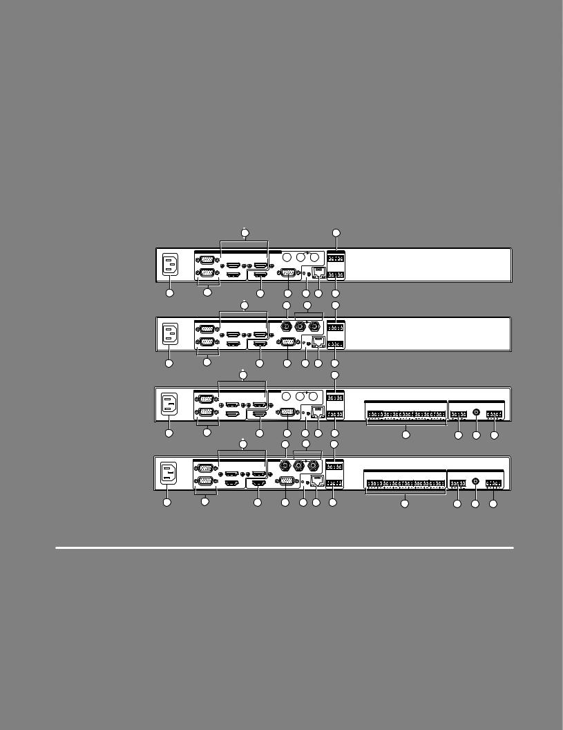
The illustration below shows all the possible rear panel features of the audio (DVS 605 A and DVS 605 AD) and the non-audio (DVS 605 and DVS 605 D) models.
3 |
15 |
DVS 605
100-240 VAC ~ .7A MAX 50/60Hz
1 |
DVS 605 D
100-240 VAC ~ .7A MAX 50/60Hz
1 |
DVS 605 A
INPUT |
OUTPUTS |
REMOTE |
1 |
|
|
|
|
|
|
|
|
|
|
|
|
3 |
5 |
AUX |
3G/HD - SDI |
|
|
1 |
2 |
3 |
4 |
5 |
|
UNIVERSAL |
|
|
GENLOCK |
|
|
CONTACT |
|
|||
|
|
|
|
|
|
|
|
|
|
|
|
2 |
4 |
HDMI |
|
|
RESET |
|
RS-232 |
IR |
|
||
|
|
|
|
|
|||||||
|
|
|
HDMI |
RGB/R-Y, Y, B-Y |
|
LAN |
Tx Rx G |
G |
S |
||
|
|
|
|
|
|
|
|
|
|
|
|
|
2 |
|
5 |
6 |
12 |
13 |
|
14 |
|
||
|
3 |
7 |
8 |
15 |
INPUT |
OUTPUTS |
|
|
REMOTE |
1 |
|
|
|
|
|
|
|
|
|
|
|
|
3 |
5 |
AUX |
3G/HD - SDI |
|
|
1 |
2 |
3 |
4 |
5 |
|
|
|
GENLOCK |
|
|||||||
|
UNIVERSAL |
|
|
|
|
CONTACT |
|
||||
|
|
|
|
|
|
|
|
|
|
|
|
2 |
4 |
HDMI |
|
|
RESET |
|
RS-232 |
IR |
|
||
|
|
|
|
|
|||||||
|
|
|
HDMI |
RGB/R-Y, Y, B-Y |
|
LAN |
Tx Rx G |
G |
S |
||
|
2 |
|
5 |
6 |
12 |
13 |
|
14 |
|
||
|
|
3 |
|
|
|
|
|
15 |
|
|
|
INPUT |
OUTPUTS |
REMOTE |
|
1 |
|
|
|
|
|
|
|
|
|
|
|
|
|
|
|
|
|
|
|
|
|
|
|
|
|
|
3 |
|
5 |
AUX |
3G/HD - SDI |
GENLOCK |
|
1 2 3 4 5 |
|
|
|
AUDIO INPUTS |
|
|
|
|
|
|
AUDIO OUTPUTS |
|
|
|||
|
|
UNIVERSAL |
|
|
|
|
CONTACT |
|
|
|
|
|
|
|
|
|
|
|
|
|
|
|
|||
|
|
|
|
|
|
|
|
|
|
|
1 |
|
2 |
|
3 |
|
4 |
|
5 |
|
|
FIXED |
|
|
|
|
2 |
4 |
HDMI |
|
|
|
|
|
|
|
|
|
|
|
|
|
FIXED |
VARIABLE |
|||||||
|
|
|
|
|
RESET |
|
RS-232 |
IR |
L |
R |
L |
R |
L |
R |
L |
R |
L |
R |
L |
R |
|
L |
R |
||
100-240 VAC ~ .7A MAX |
|
|
|
|
HDMI |
RGB/R-Y, Y, B-Y |
|
LAN |
Tx Rx G |
G |
S |
|
|
|
|
|
|
|
|
|
|
|
S/PDIF |
|
|
50/60Hz |
|
|
|
|
|
|
|
|
|
|
|
|
|
|
|
|
|
|
|||||||
1 |
|
2 |
|
|
5 |
6 |
12 |
13 |
14 |
|
|
|
|
|
4 |
|
|
|
|
|
9 |
10 |
|
11 |
|
|
|
|
3 |
|
|
7 |
8 |
|
15 |
|
|
|
|
|
|
|
|
|
|
|
|
|
|
|
|
DVS 605 AD
INPUT |
OUTPUTS |
REMOTE |
|
1 |
|
|
|
|
|
|
|
|
|
|
|
|
|
|
|
|
|
|
|
|
|
|
|
|
|
3 |
5 |
AUX |
3G/HD - SDI |
GENLOCK |
|
1 2 3 4 5 |
|
|
|
AUDIO INPUTS |
|
|
|
|
|
|
AUDIO OUTPUTS |
|
|
|||
|
|
UNIVERSAL |
|
|
|
CONTACT |
|
|
|
|
|
|
|
|
|
|
|
|
|
|
|
|||
|
|
|
|
|
|
|
|
|
|
1 |
|
2 |
|
3 |
|
4 |
|
5 |
|
|
FIXED |
|
|
|
|
2 |
4 |
HDMI |
|
|
|
|
|
|
|
|
|
|
|
|
FIXED |
VARIABLE |
|||||||
|
|
|
|
RESET |
|
RS-232 |
IR |
L |
R |
L |
R |
L |
R |
L |
R |
L |
R |
L |
R |
|
L |
R |
||
100-240 VAC ~ .7A MAX |
|
|
|
HDMI |
RGB/R-Y, Y, B-Y |
|
LAN |
Tx Rx G |
G |
S |
|
|
|
|
|
|
|
|
|
|
|
S/PDIF |
|
|
50/60Hz |
|
|
|
|
|
|
|
|
|
|
|
|
|
|
|
|
|
|||||||
1 |
|
2 |
|
5 |
6 |
12 |
13 |
14 |
|
|
|
|
|
|
4 |
|
|
|
|
|
9 |
10 |
|
11 |
Figure 1. |
DVS 605 Rear Panel Features — All Models |
||
|
|
||
Power and video input connections |
Output and control connections |
||
|
|
|
|
A AC power connector |
E HDMI connector |
K Audio out (variable), 5-pole |
|
B Universal analog 15-pin VGA connectors |
F RGB/R-Y,Y, B-Y component 15-pin VGA |
captive screw connector |
|
(audio models only) |
|||
— inputs 1 and 2 |
connector |
L Reset button and LED |
|
C HDMI connectors — inputs 3-5 |
G 3G/HD-SDI connector (optional) |
||
M RJ-45 LAN connector |
|||
(Note: PIP is not available on input 5) |
(SDI models only) |
||
|
|||
D Audio 5-pole captive screw connectors |
H Genlock connectors — input and loop |
N RS-232 and IR 5-pole captive |
|
screw connector |
|||
— inputs 1- 5 (audio models only) |
(SDI models only) |
||
|
|||
|
I Audio out (fixed), 5-pole captive |
O Contact closure 5-pole captive |
|
|
screw connector (shares a ground |
||
|
screw connector (audio models only) |
||
|
with RS-232) |
||
|
|
||
|
J RCA audio (S/PDIF) out connector |
|
|
|
(audio models only) |
|
|
|
|
|
|
DVS 605 • Rear Panel Connections |
7 |
APower input — Connect the standard IEC power cord from a 100 to 240 VAC, 50-60 Hz power source into this connector. The front panel control and input selection buttons light in sequence during power-up.
BInputs 1 and 2 — Connect suitable inputs to these two universal analog input ports (15-pin HD [VGA] connectors) for auto-detection of RGB, HD component video, YUVi, S-video, or composite video signals.
These universal analog input ports can be configured to accept RGB (RGBHV, RGBs), component video (bior tri-level), S-video, or composite video signals. The default setting is for auto detect. The table below shows the pinouts for each format type on the 15-pin HD (VGA) connector. The 15-pin HD supports EDID emulation.
Pinout Table for 15-pin HD Connector
Pin |
RGBHV |
RGBs |
Component |
S-video |
Composite |
1 |
Red |
Red |
R-Y |
|
|
2 |
Green |
Green |
Y |
Luma |
Video |
3 |
Blue |
Blue |
B-Y |
Chroma |
|
4 |
No |
No |
|
|
|
|
Connection |
Connection |
|
|
|
5 |
No |
No |
|
|
|
|
Connection |
Connection |
|
|
|
6 |
Red Return |
Red Return |
R-Y Return |
|
|
7 |
Green Return |
Green Return |
Y Return |
L Return |
Video Return |
8 |
Blue Return |
Blue Return |
B-Y Return |
C Return |
|
9 |
|
|
|
|
|
10 |
Ground |
Ground |
|
|
|
11 |
No |
No |
|
|
|
|
Connection |
Connection |
|
|
|
12 |
EDID/DDC |
EDID/DDC |
5 |
1 |
|
|
|
|
|
||
13 |
H Sync |
C Sync |
|
|
|
14 |
V Sync |
|
|
|
|
15 |
EDID/DDC |
EDID/DDC |
15 |
11 |
|
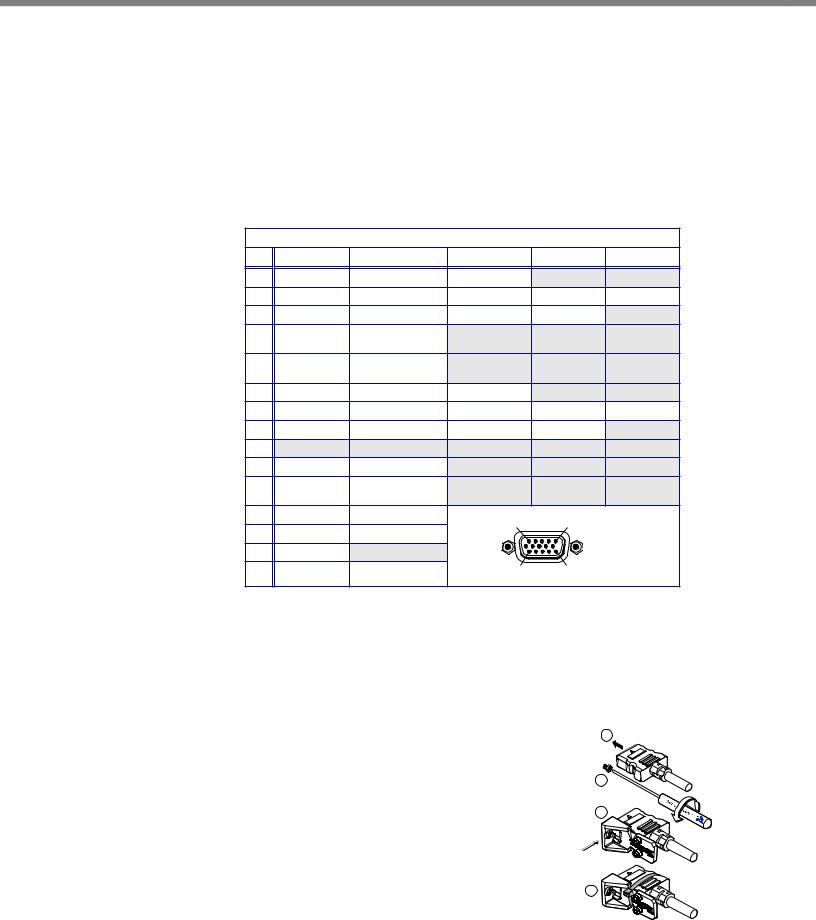
CInputs 3 to 5 — Connect HDMI sources to these three HDMI connectors.
Audio from the HDMI inputs can be de-embeded from the HDMI source. This allows the user to choose to select audio either from the HDMI inputs or the analog audio captive screw inputs. Once an audio source is selected, the unselected source is disabled. The default selection is 2-channel digital audio from the HDMI inputs.
Connect up to three digital HDMI and DVD-D inputs to the HDMI connectors C. Connect DVI-D sources using an adapter cable and secure the connectors to the
DVS using the LockIt™ bracket as follows: |
1 |
|
1.Plug the HDMI cables into the panel connections.
2.Loosen the side HDMI connection mounting screw from the panel enough to allow the LockIt
lacing bracket to be placed over it.
3.Place the LockIt lacing bracket onto the screw and slide it up against the HDMI connector. Tighten the screw to secure the bracket.
4.Loosely place the included tie wrap around the HDMI connector and LockIt lacing bracket.
2
3
4
DVS 605 • Rear Panel Connections |
8 |
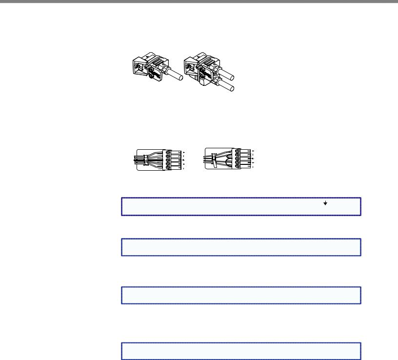
5.While holding the connector securely against the lacing bracket, tighten the tie wrap, then remove any excess length.
The LockIt bracket can also be used in a stacked formation, as shown below.
Side Mounted |
Stacked |
Figure 2. LockIt Bracket Mounting Options
DAudio inputs 1-5 (audio models only) — Connect audio sources to these 5-pole captive screw connectors. Wire the connector for line level, balanced or unbalanced, analog stereo as shown below.
Tip |
L |
Tip |
|
Ring |
|||
Sleeves |
|
Sleeve |
|
|
Tip |
||
Tip |
|
||
R |
Sleeve |
||
Ring |
|||
|
|
R L
Balanced Stereo Input |
Unbalanced Stereo Input |
|
Figure 3. |
Audio Input Connector Wiring |
|
NOTE: |
Control signal ground pins are labeled “G”. Audio ground pins are as . |
|
|
The wiring and function are the same, whichever way your product is labeled. |
|
E HDMI output — Connect an HDMI display device to this HDMI connector.
NOTE: All video outputs (HDMI, VGA, SDI) share a common output resolution and display |
the same content. |
FRGB or HD component (R-Y, Y, B-Y) 15-pin HD video output — Connect an RGB video display or HD component video display to this HD 15-pin connector.
NOTE: Simultaneous identical scaled outputs for HDMI and analog RGB or HD |
component video are available. |
GOptional 3G-SDI/HD-SDI output connector — Connect an SDI (serial digital interface) display to this female BNC connector for SDI output. This complies with SMPTE 292M and 424M and ITU video digital standards.
NOTE: 3G/HD-SDI output is only active if the current resolution is set to 720p, 1080i, |
1080p, or 2k 23.98/24/25 hz. |
HGenlock connector and loop through (SDI models only) — Connect an external reference signal for synchronization of the SDI output. The loop through can be used to synchronize additional devices.
DVS 605 • Rear Panel Connections |
9 |
IAudio output (fixed, audio models only) — Connect audio output devices to this 5-pole, captive screw connector for line level, balanced or unbalanced, analog stereo. Wire the connectors as shown below.
Tip |
Ring |
Sleeves |
Tip |
Ring |
|
No Ground Here |
L |
Tip |
|
|
|
Sleeves |
|
Tip |
R
No Ground Here
R L
Do not tin the wires!
Balanced Audio Output |
Unbalanced Audio Output |
Figure 4. Audio Output Connector Wiring
JRCA audio output (S/PDIF, fixed, audio models only) — Plug in an S/PDIF audio output device into this female RCA connector. This connector outputs digital S/PDIF audio formats (2-channel LPCM, Dolby Digital, or DTS).
KAudio output (variable, audio models only) — Connect audio output devices to this 5-pole, captive screw connector for line level, balanced or unbalanced, analog stereo. Wire the connectors as shown below.
Tip |
Ring |
Sleeves |
Tip |
Ring |
|
No Ground Here |
L |
Tip |
|
|
|
Sleeves |
|
Tip |
R
No Ground Here
R L
Do not tin the wires!
Balanced Audio Output |
Unbalanced Audio Output |
Figure 5. Audio Output Connector Wiring
LReset button and LED — Using an Extron Tweeker, pointed stylus, or ballpoint pen, press this recessed button for manual resets. The unit has four modes of reset (see “Resetting the Unit” on page 33 for additional information). The green LED flashes to show the reset mode indications and that power is on.
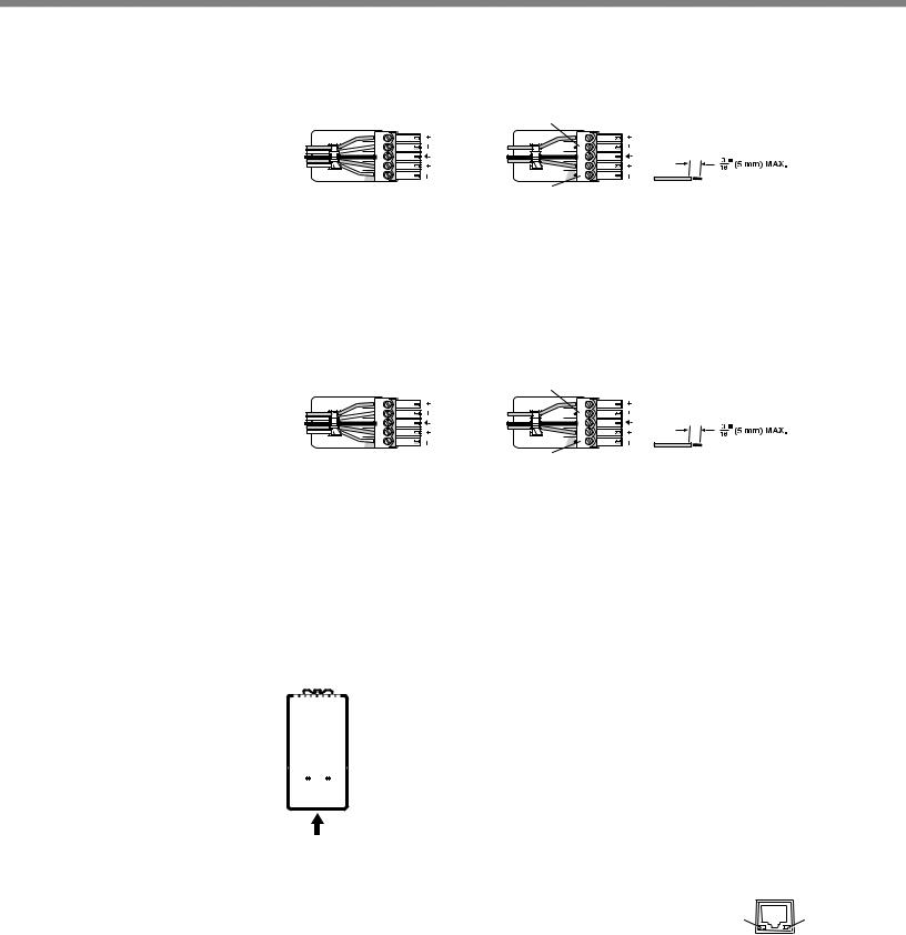
MLAN connector — Plug an RJ-45 jack into this socket to connect the unit to a computer network. Use a patch cable to connect to a switch, hub, or router.
Wire the connector as shown below.
|
|
Pins: |
|
|
|
|||
12345678 |
|
|
|
|
|
|
||
|
|
|
|
T568A |
T568B |
|||
|
|
|
|
|
|
|
||
|
|
|
|
|
|
Pin |
Wire color |
Wire color |
|
|
|
|
|
|
|
|
|
|
|
|
|
|
|
1 |
White-green |
White-orange |
|
|
|
|
|
|
|||
|
|
|
|
|
|
|
|
|
|
|
|
|
|
|
2 |
Green |
Orange |
|
|
|
|
|
|
|||
|
|
|
|
|
|
|||
|
|
|
|
|
|
3 |
White-orange |
White-green |
|
|
|
|
|
|
|||
|
|
|
|
|
|
|
|
|
|
|
|
|
|
|
4 |
Blue |
Blue |
|
|
|
|
|
|
5 |
White-blue |
White-blue |
|
|
|
|
|
|
|
|
|
|
|
|
|
|
|
6 |
Orange |
Green |
|
|
|
|
|
|
|
|
|
|
|
|
|
|
|
7 |
White-brown |
White-brown |
|
|
|
|
|
|
|
|
|
Insert Twisted |
8 |
Brown |
Brown |
|||||
|
Pair Wires |
|
|
|
||||
RJ-45 Connector |
|
|
|
|||||
Figure 6. RJ-45 LAN Connector Wiring
Activity Link
LAN Activity LED — A blinking yellow LED indicates LAN activity.
LAN
Link LED — The green LED lights to indicate a good LAN connection.
DVS 605 • Rear Panel Connections |
10 |

NRS-232/IR port — For serial RS-232 control, connect a host computer or control system to the 5-pole captive screw connector. This port is also a hard wired IR control for use with an external IR controller.
The default RS-232 protocol is 9600 baud, 1 stop bit, no parity, 8 data bits, no flow control.
By default the IR port is disabled. When enbled, the IR port accepts 38 kHz to 1 MHz, modulated signals at TTL level (0-5 V)
ORemote contact closure port — For remote input selection of any of the five inputs, connect a suitable contact closure control device to this 5-pole captive screw connector. The contact closure port and the RS-232 port share a common ground.
DVS 605 • Rear Panel Connections |
11 |
Operation
This section of the manual discusses the operation of a DVS 605 device.
Topics covered include:
•Front Panel Overview
•Powering Up
•The DVS 605 Menu System — Configuration and Adjustments
•Front Panel Lockout (Executive Modes)
•Window vs. Image Size Position — An Overview
•Picture-in-Picture (PIP) Mode
•Other DVS 605 Operating Features
Front Panel Overview
|
|
|
3 |
|
1 |
2 |
3 |
AUTO |
|
|
|
|
|
EXTRON |
4 |
5 |
PIP |
SWAP |
DVS 605 |
CONFIG |
|
|
|
|
|
DVS 605 |
|
MENU |
DIGITAL VIDEO SCALER |
|
ADJUST
NEXT
1 |
2 |
4 |
5 |
6 |
7 |
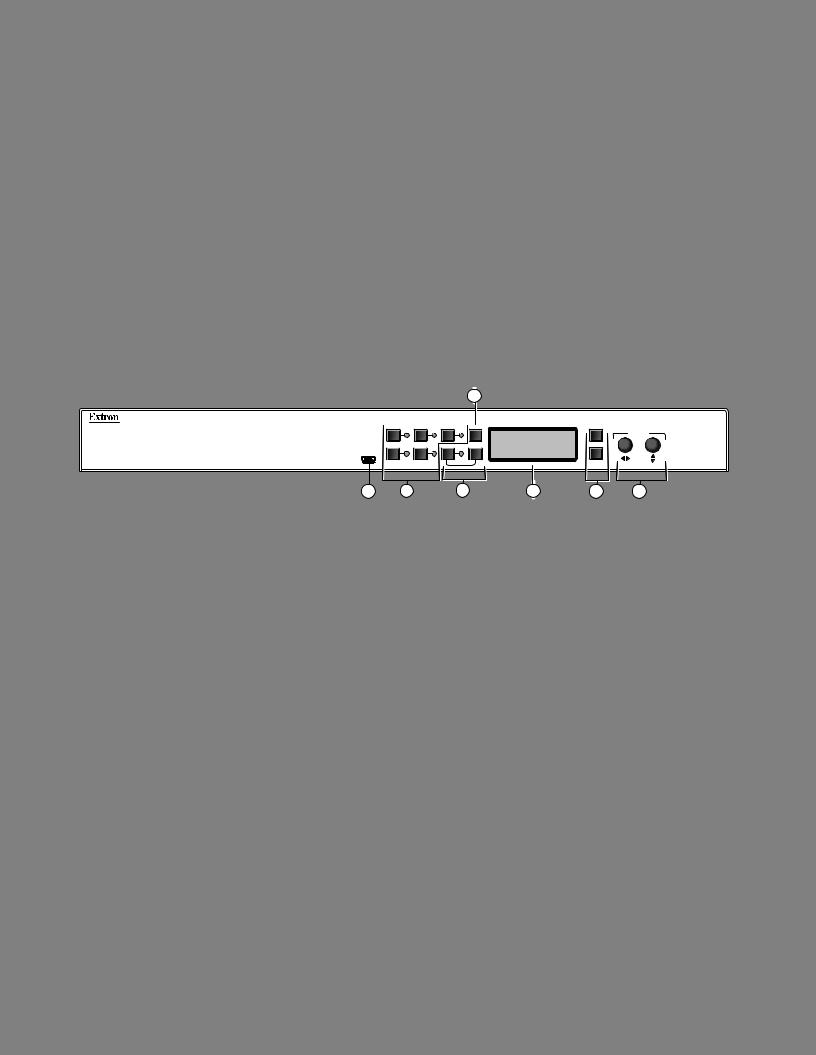
Figure 7. DVS 605 Front Panel Features
AMini USB configuration port — Connect a control system or computer to this front panel mini USB port for device configuration, control, and firmware upgrades.
BInput selection buttons and LEDs (1-5) —
Input LEDs — The LED of the selected input lights when the button is pressed. A blinking LED indicates an audio breakaway input (audio models only).
Inputs 1 and 2 (universal input buttons) — Inputs 1 and 2 select Auto detect, RGB scaled (RGBHV, RGBS, RGsB), Auto-YUV, RGBcvS, S-video, and composite video inputs.
Inputs 3, 4, and 5 (HDMI/DVI buttons) — Inputs 3, 4, and 5 select HDMI/DVI inputs
CAuto-Image button — Use this to start an Auto-Image function which automatically sizes and centers an input signal.
DPIP (Picture-In-Picture) button and Swap image button — The PIP button enables or disables the PIP mode. The Swap button allows the user to swap the two current inputs displayed in the main and PIP windows.
ELCD display — Displays configuration menus and status information. See “The DVS 605 Menu System — Configuration and Adjustments” section on page 13 for details.
FMenu navigation buttons (Menu and Next) —
Menu — Use this button to enter and move through the main menu system.
Next — Use this button to step through the submenus of the scaler menu system. See the “The DVS 605 Menu System — Configuration and Adjustments” section on the next page for details.
GAdjustment knobs (horizontal [and vertical {) — Using the menu system, rotate either of these two knobs to scroll through the menu and to make any adjustments.
DVS 605 • Operation |
12 |
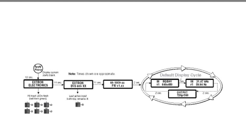
Powering Up
When applying power to the DVS 605, the unit undergoes a start-up self testing sequence (see image below) and then the LCD displays the default display cycle.
Default Display Cycle
When in use but not in any menu mode, the LCD screen defaults to cycling through the input/output configuration currently installed. The displayed content may vary, depending on the input video signal type. See figure 8 for a typical default display cycle.
Figure 8. Typical Default Display Cycle
The default display cycle shows the scaler output rate and refresh rates for the currently selected input.
The DVS 605 Menu System — Configuration and Adjustments
Scaler configuration and adjustments can be performed by using the embedded web pages (see “Using Default Web Pages” starting on page 60 ), the Extron Simple Instruction Set (SIS) of commands (see “SIS Communication and Control” starting on page 34), or by using the front panel controls and the menus displayed on the DVS unit’s LCD screen. These menus are used primarily when the scaler is first set up.
Menu Navigation Using Front Panel Controls
Menu button — Press the Menu button to activate menus and scroll through the eight main menus.
Next button — Press the Next button to move between the submenus of a selected main menu item.
Adjust ([,{) knobs — In configuration mode, rotate the Adjust horizontal ([) knob and Adjust vertical ({) knob to scroll through submenu options and to make adjustment selections. See the flowcharts in this chapter for explanations on knob adjustments.
DVS 605 • Operation |
13 |
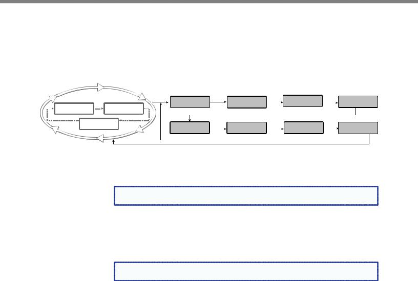
Menu Overview
After start-up, and when no adjustments are actively being made, the “default cycle” appears on the LCD. The screens cycle between the screen that shows the number and video format of the active input and the current output resolution.
Pressing the Menu button once brings up the first of eight main (top level) menus, as shown below. Each successive press of the Menu button goes to the next main menu.
|
Default Display Cycle |
USER |
Menu |
PICTURE |
Menu |
INPUT |
Menu |
|
OUTPUT |
||||||||||
|
|
|
|
|
2 |
|
|
|
PRESETS |
|
CONTROL |
|
CONFIG |
|
|
|
CONFIG |
||
|
|
|
|
|
|
|
|
|
|
|
|
||||||||
|
IN |
|
RGBHV |
|
|
sec |
IN |
31.47 kHz |
|
|
|
|
|
|
|
|
|
|
|
|
|
|
|
|
|
#1 |
59.94 Hz |
|
|
|
|
|
|
|
|
|
|
||
480 |
|
|
|
|
|
|
|
|
|
|
|
Menu |
|||||||
|
|
|
|
|
|
|
|
|
|
|
|
|
|
|
|
|
|
||
|
|
|
|
|
|
|
|
|
|
|
|
|
|
|
|
||||
2 sec. |
|
OUTPUT |
|
2 sec. |
AUDIO |
Menu |
ADVANCED |
Menu |
VIEW COMM |
Menu |
|
EXIT MENU? |
|||||||
|
|
|
|
||||||||||||||||
|
|
|
|
|
|
720p@60 |
|
|
|
||||||||||
|
|
|
|
|
|
|
|
|
|
CONFIG |
|
CONFIG |
|
SETTINGS |
|
|
PRESS NEXT |
||
|
|
|
|
|
|
|
|
|
|
Menu |
|
|
|
|
|
|
Menu |
Next |
|
|
|
|
|
|
|
|
|
|
|
Next |
|
|
|
|
|
|
|
|
|
Figure 9. Top Level Menus
A fourth default cycle menu appears only when genlock is enabled. See “Genlock/AFL Mode”on page 20) for details.
NOTE: From any menu or submenu, after 20 seconds of inactivity the DVS will save |
all adjustment settings and time-out to the default cycle. |
The flowchart shown on page 15 provides an overview of the complete menu system, with configuration submenus and the options for each setting. In the flow charts the use of “x”, (for example in (x) or Inx) indicates an input number.
Use the Menu button to scroll between top level menus and press Next to enter the submenus.
NOTE: If no signal is present on the currently selected input, NO SIGNAL appears in |
place of the input type. For example, INPUT 4 NO SIGNAL. |
Details of each of the menus are on subsequent pages after the main flow chart.
DVS 605 • Operation |
14 |

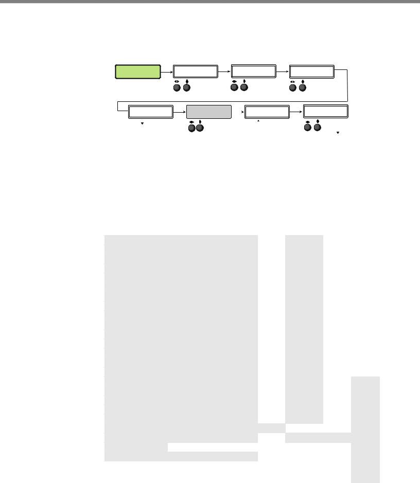
15 Operation • 605 DVS
USER |
Menu |
PICTURE |
Menu |
INPUT |
Menu |
OUTPUT |
Menu |
AUDIO |
Menu |
PRESETS |
|
CONTROL |
|
CONFIG |
|
CONFIG |
|
CONFIG |
|
Next |
|
Next |
|
Next |
|
Next |
|
Next |
|
INx RECALL |
(x)H |
POS |
V |
INPUT #x |
RESOLUTION |
VOLUME |
<N/A> |
+00000+00000 |
RGB |
1080p@60 |
-30dB |
||
Rotate either to select a preset to recall settings.
Next
INx SAVE
<02>
Rotate either
to select a preset to save current settings to.
NOTE: Where used in this flow chart “x” indicates the input number.
Rotate to adjust horizontal position. Rotate
 to adjust vertical position.
Next
(x)H SIZE V
00000 00000
Rotate to adjust horizontal size. Rotate
 to adjust vertical size.
Next
(x)BRIT CONT
064* *064
Rotate to adjust brightness.
Rotate to adjust contrast (* = default).
Next
(x)COL TINT
064* *064
Rotate to adjust color.
Rotate to adjust tint (* = default).
Next
(x)DETAIL *064
Rotate either to select input signal type.
Next
(x)FILM MODE
OFF
Rotate either to turn film mode off or to Auto.
Next
(x)H START V
128 128
Rotate to adjust horizontal start. Rotate
 to adjust vertical start.
Next
(x)H ACT V 1024* *0768
Rotate to select resolution.
Rotate to select refresh rate
Next
VGA FORMAT
RGBHV
Rotate either to select the VGA format.
Next
H-SYNCV-
Rotate either to

 set sync values.
Next
HDMI FORMAT
AUTO
Rotate  to adjust horizontal active pixels. Rotate
  to adjust vertical active pixels
(* = default).
Next
(x)TPIX PHAS
1344* 01
Rotate either to

 set HDMI format.
Next
HDCP NOTE
OFF <ON>
Rotate either to turn HDCP note on or off.
Rotate either to set detail level (* = default).
Rotate to adjust total pixels
(* = default). Rotate  to adjust phase.
Next
INx EDID 1600x1200@60
Rotate
 to set an EDID value for the active input.
NOTE: The Input Configuration submenus are input specific and some menus may not be available depending on the input type.
Next
GENLOCK/AFL
OFF
Rotate either to

 set genlock mode.
Next
H OFFSET V 110 75
Rotate to adjust horizontal offset. Rotate
 to adjust vertical offset.
Rotate either to

 set volume level.
Next
AUDIO MUTE <OFF> ON
Rotate either to turn audio mute on or off.
Next
INx GAIN/ATT
0 dB
Rotate either to set gain and attenuation level.
Next
INx FORMAT
DIGITAL
Rotate either to select input audio format.
Next
AUDIO OUTPUT
STEREO
Rotate either to select audio output format.
ADVANCED |
Menu |
VIEW COMM |
Menu |
EXIT MENU? |
||
CONFIG |
|
SETTINGS |
|
PRESS NEXT |
||
|
|
|||||
|
Next |
|
|
Next |
|
|
|
|
|
|
|
||
|
|
|
|
|
|
|
AUTO IMAGE
Input #x OFF
Rotate  to turn Auto Image mode on or off.
Next
ASPECT RATIO
IN#x FILL
Rotate either to select aspect ratio mode.
Next
SERIAL PORT 9600 RS232
Next
MAC ADRESS 005A6078CEC
This is set at the factory and cannot be changed in “Edit Comm Settings” menu. Next
DHCP MODE
On
AUTO MEMORY |
|
Next |
|
IN#x ON |
I |
192.168 |
|
Rotate either to turn |
|||
P |
254.254 |
||
auto memory on |
|
|
|
or off for selected input. IP address |
Next |
||
Next |
S |
255.255 |
|
|
|||
OVERSCAN |
M |
000.000 |
|
S-VIDEO 5.0% |
Subnet mask |
Next |
|
|
|||
|
|
||
Rotate either to set |
G |
192.168 |
|
the overscan mode. |
|||
Next |
W |
000.000 |
|
Gateway address |
|||
|
|||
SWITCH TYPE
DISSOLVE
Rotate either to change switch type.
Next
“Hidden” Menu *
EDIT COMM
SETTINGS
Next
SERIAL PORT 9600 RS232
Rotate  to select RS-232 mode. Rotate
 to change baud rate.
Next
DHCP MODE <ON>
Rotate either to turn
DHCP mode on or off.
Next
I |
192.168 |
P |
254.254 |
|
Rotate |
to select |
|
octet field. Rotate |
|
|
to change IP address. |
|
|
Next |
|
S |
255.255 |
|
M |
000.000 |
|
|
Rotate |
to select |
octet field. Rotate
to change Subnet address.
TEST PATTERN
COLOR BARS
Rotate either to change test pattern.
Next
OSD DURATION
125 SEC
Rotate either to change OSD duration.
Next
TEMPERATURE
96 F 35 C
Indicates internal temperature (not adjustable).
Next
FACT. RESET
HOLD AUTO
Press and hold Auto button
to reset unit to factory settings.
|
Next |
G |
192.168 |
W |
000.000 |
|
Rotate to select |
|
octet field. Rotate |
|
to change Gateway address. |
*NOTE: To activate the hidden menu “Edit Comms”, press and hold input 5 and Next buttons simultaneously for three seconds.
To exit the Edit Comms menu press Menu.
Figure 10. Main Menu
To return to the default cycle from within any menu, press the Menu button repeatedly until the Exit menu appears, then press the Next button. Alternatively, allow the DVS 605 to time-out (after 20 seconds).
Submenus are accessed from a main menu by pressing the Next button. When within a submenu, press the Menu button to go out of the submenu and back to the active main menu.
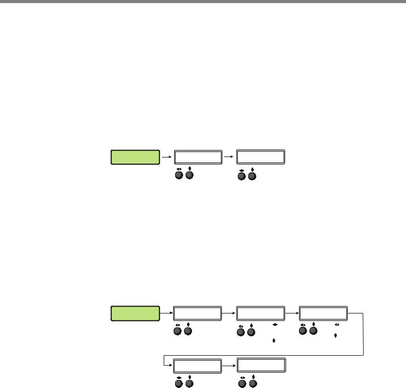
User Presets
This menu alows the user save or recall up to 16 presets for the selected input, shown as INx on the LCD screen.
To use this menu press Next to get the relevant submenu, Recall or Save.
When within the submenu use the Adjust knobs to select the preset to save or recall.
Press Menu to exit the submenu.
USER |
Next |
INx RECALL |
Next |
|
|
||
PRESETS |
|
<N/A> |
|
Rotate either to select a preset to recall settings.
INx SAVE
<02>
Rotate either
to select a preset to save current settings to.
Figure 11. User Preset Menu
Picture Control
This menu allows the user to adjust various picture control settings such as horizontal and vertical window positioning, horizontal and vertical window size, brightness and contrast, color and tint, and detail settings for the selected input. The selected input is shown as (x) on the LCD screen.
To use this menu press Next to get the relevant submenu.
When within the submenu use the adjust knobs to select and then adjust the values as desired.
Press Menu to exit the submenu.
PICTURE |
Next |
(x)H POS V |
Next |
|
|
||
CONTROL |
|
+00000+00000 |
|
Rotate  to adjust window horizontal position.
Rotate  to adjust window vertical position.
Next |
(x)COL |
TINT |
Next |
|
|
064* *064
Rotate  to adjust color.
Rotate  to adjust tint (* = default).
(x)H |
SIZE V |
Next |
(x)BRIT |
CONT |
Next |
00000 |
00000 |
|
064* |
*064 |
|
|
Rotate |
to adjust |
Rotate |
to adjust |
|
|
window horizontal |
brightness. |
|||
|
size. |
|
Rotate to adjust |
||
|
Rotate |
to adjust |
contrast (* = default). |
||
window vertical size.
(x)DETAIL *064
Rotate either to set detail level (* = default).
Figure 12. Picture Control Menu
DVS 605 • Operation |
16 |
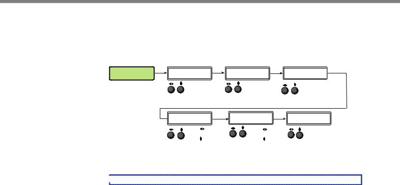
Input Configuration
This menu allows the user to adjust various input configuration settings such as video signal type, film mode, horizontal and vertical start position, horizontal and vertical active pixels, total pixel number, phase, and EDID settings for the selected input. The selected input is shown as (x) on the LCD screen images.
INPUT |
Next |
|
|
CONFIG |
|
Next
INPUT #x |
Next |
|
|
||
RGB |
|
|
|
Rotate either to |
|
|
select input |
|
|
signal type. |
|
(x)H |
ACT V |
Next |
1024* |
*0768 |
|
(x)FILM MODE |
Next |
|
|
OFF |
|
Rotate either to turn film mode off or to Auto.
(x)TPIX PHAS Next
1344* 01
Rotate |
to adjust |
Rotate |
to adjust |
horizontal active pixels. |
total pixels. |
||
Rotate |
to adjust |
Rotate |
to adjust |
vertical active pixels |
phase (* = default). |
||
(* = default). |
|
|
|
(x)H |
START V |
|
Next |
|
|||
027 |
029 |
|
|
Rotate  to adjust horizontal start position. Rotate
  to adjust vertical start position.
INx EDID 1600x1200@60
Rotate to set EDID resolution for the active input. Rotate
  to set refresh rate.
Figure 13. Input Configuration Menu
 NOTE: Only inputs 1 and 2 offer selectable video types.
Input video types
Rotate either the Adjust horizontal ([) or Adjust vertical ({) knob while in any of the Input submenus to select the appropriate video format.
Input 1
Input 1 is a universal analog input for RGB scaled, Auto YUV, RGBcvS, S-video and composite video.
When input 1 is set to YUV Auto, the scaler detects if YUVi or YUVp/HDTV is applied and sets the input accordingly.
It can also be set to autodetect the incoming input signal type. This is the default setting.
Input 2
Input 2 is a universal analog input for RGB scaled, Auto YUV, RGBcvS, S-video and composite video.
When input 2 is set to YUV Auto, the scaler detects if YUVi or YUVp/HDTV is applied and sets the input accordingly.
It can also be set to autodetect the incoming input signal type. This is the default setting.
Inputs 3-5
Input 3 through 5 are digital inputs for HDMI or DVI input signals.
DVS 605 • Operation |
17 |
Output Configuration
The output configuration menu allows selection of output resolution and refresh rates, analog output types (RGBHV, RGBS, RGsB and Y, B-Y, R-Y), sync polarity, HDMI format, HDCP notification display, genlock setting, and offset values.
OUTPUT |
Next |
RESOLUTION |
Next |
CONFIG |
|
1365x1024@60 |
|
Rotate  to select a resolution. Rotate
  to select a refresh rate.
VGA FORMAT |
Next |
SYNC |
Next |
|
|
||||
RGBHV |
|
H- |
V- |
|
Rotate either to |
|
Rotate either to |
||
select VGA |
|
|
set sync values. |
|
format. |
|
|
|
|
HDMI FORMAT |
Next |
AUTO |
|


 Rotate either to
 set HDMI format.
|
Next |
HDCP NOTE |
|
OFF <ON> |
|
Rotate either to tun HDCP note on or off.
GENLOCK/AFL Next
OFF


 Rotate either to
 set genlock mode.
H OFFSET V 110 75
Rotate  to adjust horizontal offset. Rotate
  to adjust vertical offset.
Figure 14. Output Configuration Menu
Resolutions and Refresh Rates
Rotate the horizontal ([) knob to select a resolution, and the vertical ({) knob for refresh rates. The default resolution and rate is 720p/60 Hz.
There are also 5 custom, user-defined/captured rates available (C1 - C5). When no rate is captured or uploaded to any of the 5 custom memory slots, they default to 720p/60 Hz.
Resolution |
23.98 Hz |
24 Hz |
25 Hz |
29.97 Hz |
30 Hz |
50 Hz |
|
59.94 Hz |
60 Hz |
75 Hz |
|
|
|
|
|
|
|
|
|
|
|
|
|
|
|
|
|
|
|
|
|
|
Custom 1 through 5 |
|
|
|
For captured or uploaded EDID tables |
|
|
|
|||
|
|
|
|
|
|
|
|
|
|
|
640 x 480 |
|
|
|
|
|
X |
|
|
X |
X |
|
|
|
|
|
|
|
|
|
|
|
800 x 600 |
|
|
|
|
|
X |
|
|
X |
X |
|
|
|
|
|
|
|
|
|
|
|
852 x 480 |
|
|
|
|
|
X |
|
|
X |
X |
|
|
|
|
|
|
|
|
|
|
|
1024 x 768 |
|
|
|
|
|
X |
|
|
X |
X |
|
|
|
|
|
|
|
|
|
|
|
1024 x 852 |
|
|
|
|
|
X |
|
|
X |
X |
|
|
|
|
|
|
|
|
|
|
|
1024 x 1024 |
|
|
|
|
|
X |
|
|
X |
X |
|
|
|
|
|
|
|
|
|
|
|
1280 x 768 |
|
|
|
|
|
X |
|
|
X |
X |
|
|
|
|
|
|
|
|
|
|
|
1280 x 800 |
|
|
|
|
|
X |
|
|
X |
X |
|
|
|
|
|
|
|
|
|
|
|
1280 x 1024 |
|
|
|
|
|
X |
|
|
X |
X |
|
|
|
|
|
|
|
|
|
|
|
1360 x 765 |
|
|
|
|
|
X |
|
|
X |
X |
|
|
|
|
|
|
|
|
|
|
|
1360 x 768 |
|
|
|
|
|
X |
|
|
X |
X |
|
|
|
|
|
|
|
|
|
|
|
1365 x 768 |
|
|
|
|
|
X |
|
|
X |
X |
|
|
|
|
|
|
|
|
|
|
|
1366 x 768 |
|
|
|
|
|
X |
|
|
X |
X |
|
|
|
|
|
|
|
|
|
|
|
1365 x 1024 |
|
|
|
|
|
X |
|
|
X |
X |
|
|
|
|
|
|
|
|
|
|
|
1440 x 900 |
|
|
|
|
|
X |
|
|
X |
X |
|
|
|
|
|
|
|
|
|
|
|
1400 x1050 |
|
|
|
|
|
X |
|
|
X |
|
|
|
|
|
|
|
|
|
|
|
|
1600 x 900 |
|
|
|
|
|
X |
|
|
X |
|
|
|
|
|
|
|
|
|
|
|
|
1680 x 1050 |
|
|
|
|
|
X |
|
|
X |
|
|
|
|
|
|
|
|
|
|
|
|
1600 x 1200 |
|
|
|
|
|
X |
|
|
X |
|
|
|
|
|
|
|
|
|
|
|
|
1920x1200 |
|
|
|
|
|
X |
|
|
X |
|
|
|
|
|
|
|
|
|
|
|
|
480p |
|
|
|
|
|
|
|
X |
X |
|
|
|
|
|
|
|
|
|
|
|
|
576p |
|
|
|
|
|
X |
|
|
|
|
|
|
|
|
|
|
|
|
|
|
|
720p |
|
|
X |
X |
X |
X |
|
X |
X |
|
|
|
|
|
|
|
|
|
|
|
|
1080i |
|
|
|
|
|
X |
|
X |
X |
|
|
|
|
|
|
|
|
|
|
|
|
1080p |
X |
X |
X |
X |
X |
X |
|
X |
X |
|
|
|
|
|
|
|
|
|
|
|
|
2k |
X |
X |
X |
X |
X |
X |
|
X |
X |
|
|
|
|
|
|
|
|
|
|
|
|
DVS 605 • Operation |
18 |

When a new custom rate has been captured or uploaded, the on-screen display (OSD) dynamically updates with the new rate for that custom slot. For example if a custom 480p EDID is uploaded to slot C1, the LCD would read “C1: 720x480”. These five custom slots are shared between custom output resolutions (based on preferred timings 1 block) and custom EDID tables, which can be assigned to any DVS input.
Analog Output Format
Using either of the Adjust knobs ([ {), select the output video format required by the display: RGBHV (default), RGBS, RGsB, YUV bi-level, and YUV tri-level.
Sync Polarity
Some display devices may require a particular combination of horizontal (H) and vertical
(V) sync signal polarities. Select the appropriate combination of positive or negative H and V sync by rotating either the Adjust horizontal ([) or the Adjust vertical ({) knob.
NOTE: If the output format was specified as RGsB or YUV, or RGBS, this submenu |
will not be displayed because this menu is only applicable for RGBHV. |
HDMI Format
Using either of the Adjust knobs ([ {), select the HDMI format as follows:
•Auto — (based on sink EDID), default
•DVI RGB 444
•HDMI RGB 444 FULL (0-255, audio, InfoFrames)
•HDMI YUV 444 FULL (0-255, audio, InfoFrames)
•HDMI YUV 444 LIMT (16-235, audio, InfoFrames)
•HDMI YUV 422 FULL (0-255, audio, InfoFrames)
•HDMI YUV 422 LIMT (16-235, audio, InfoFrames)
HDCP Notification
The HDCP Notification provides a means of determining if HDCP content restrictions are preventing a video signal from passing. The DVS 605 has the ability to notify the user that they are currently trying to view HDCP protected content through a non-HDCP compliant output port (15-pin HD or 3G/HD-SDI) or a non-HDCP compliant HDMI/DVI display. The options presented to the user during this scenario are the ability to show a green screen with a moving “OSD bug” (see page 32) reading “HDCP CONTENT,” or to disable this message, and instead output muted (black) video on non-HDCP compliant displays.
The HDCP Notification setting can be adjusted via the front panel menu by using either of the Adjust knobs ([ {), to turn HDCP notification on or off.
HDCP CONTENT
Figure 15. Green HDCP Notification Screen
It can also be adjusted via the internal web pages or SIS commands.
DVS 605 • Operation |
19 |

HDCP Status: Inputs & Outputs
Through a series of SIS commands (see “SIS Communication and Control” starting on page 34) the DVS 605 has the ability to report HDCP status of the HDMI input signals as well as connected HDMI sink devices. When the unit is queried, it reports feedback on the specified input (source) or output (sink) as follows:
•There is no sink or source attached.
•The connected sink supports HDCP, or the connected source is currently providing a HDCP encrypted signal.
•The connected sink does not support HDCP, or the connected source is currently providing an unencrypted signal.
HDCP status of the current input can be viewed on the OSD bug. If the input is encrypted the OSD bug displays an HDCP padlock symbol. The HDCP status of the currently selected input, and the capabilities of the connected HDMI sink device, can also be viewed on the AV Controls bar within the internal web pages of the unit.
HDCP Authorized
The HDCP Authorized function allows the DVS 605 HDMI inputs to be able to report as an HDCP authorized sink or a non-HDCP authorized sink device to a source. This is
especially useful for sources that will encrypt their output even if the source material does not require HDCP encryption, which would then prevent content from being displayed on non-HDCP compliant displays.
For example, if the user wanted to show a non-HDCP protected presentation from a PC using the HDMI output of the PC, there is a chance that the PC will encrypt the HDMI, because it can see that the DVS 605 HDMI input supports HDCP authorization. If the user were only going to use the HDMI output of the DVS 605 to a display (sink) that supported HDCP, there would be no issue; however, if the user wanted to use the DVS 605 analog 15-pin HD output to an analog sink (display), the green HDCP notification screen would be displayed, due to the source unnecessarily enabling encryption on its HDMI output.
By disabling HDCP authorization on one of the DVS 605 HDMI inputs, the PC with nonHDCP protected content will determine that the signal path does not support HDCP, and therefore will not encrypt its output. With HDCP authorization disabled on the DVS 605’s input, the user will be able to view their non-HDCP protected content from any video output of the DVS 605. With HDCP authorized disabled on an input, if HDCP protected content is selected on the source, the source will either simply mute its video output to black, or display a warning message to the user.
Genlock/AFL Modes
The DVS 605 has the ability to lock the output vertical refresh rate to the selected input signal vertical refresh rate (AFL), or to an applied SDI Genlock signal (SDI models only).
The 3 available modes for genlock are:
•Off — A free running pixel clock is generated internally by the DVS 605.
•Input AFL — This mode locks the output vertical refresh rate to the vertical refresh rate of the currently selected input using Extron Accu-Rate Frame Lock technology to ensure no frames of the input are repeated or dropped due to frame rate conversion. This mode will result in glitches / interruptions in output sync when a new DVS 605 input is selected, or when a new signal has been routed to the DVS 605 selected input, as the DVS 605 locks to the vertical refresh rate of the new input. If no input signal is detected, or if locking to the input signal would result in a >165 MHz pixel clock, a free running pixel clock is generated by the DVS 605.
DVS 605 • Operation |
20 |
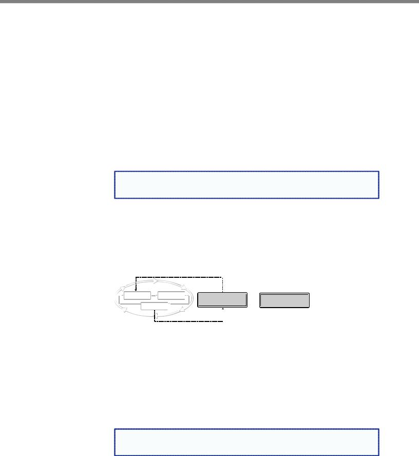
•SDI Genlock (SDI models only) — This locks the output vertical refresh rate to the applied analog genlock input on the SDI models. In the SDI Genlock mode, the output resolution and refresh rate of the DVS 605 must be set to exactly match the applied analog genlock signal to ensure a true genlock to the applied SDI Genlock signal.
If the applied SDI Genlock signal does not exactly match the resolution and refresh rate of the DVS 605 output resolution, the DVS 605 will lock its output vertical refresh to that of the applied SDI reference (frame lock), which may result in more jitter.
If no SDI Genlock signal is detected, or if the detected SDI Genlock signal would result in a >165 MHz pixel clock, a free running pixel clock is generated by the DVS 605.
If either Genlock/AFL mode has been enabled, a conditional “Genlock/AFL Locked” “Genlock/AFL Not Locked” LCD menu will be added to the DVS 605 default menu cycle to indicate the current Genlock/AFL status. The Genlock/AFL status can also be queried via SIS command.
When using the SDI genlock, the output rate of the DVS 605 must be set to match the applied SDI genlock reference signal, for example 1080i at 59.94 Hz
NOTE: When the DVS 605 is set for input signal lock, a glitch in output sync may |
be experienced when switching between inputs as the scaler locks to the input |
reference. |
If either genlock mode is enabled, but no genlock or reference input signal is being applied to the scaler, the DVS 605 defaults to an internally generated vertical refresh rate that matches the current output resolution setting.
Genlock/AFL can be enabled via the front panel menu system by using either of the Adjust knobs ([ {), to turn Genlock/AFL off, set to Input AFL signal, or set to SDI Genlock (where applicable).
When genlock/AFL is enabled a fourth default cycle menu appears.
2 sec.
Default Display Cycle
|
|
|
|
2 |
IN |
31.47 kHz |
|||
|
IN |
|
RGBHV |
|
|
sec. |
|||
|
|
|
|
|
#1 |
59.94 |
Hz |
||
480 |
|
|
|
||||||
|
|
|
|
|
|
|
|||
2 sec. |
OUTPUT |
|
|
2 sec. |
|||||
|
|
|
|
|
720p |
|
|
|
|
GENLOCK/AFL |
OR |
GENLOCK/AFL |
LOCKED |
|
NOT LOCKED |
2 sec.
Figure 16. Fourth Default Display Item — Genlock/AFL Menu
This menu is only visible when genlock is enabled.
Genlock/AFL Offset Description
When used in a genlocked system, the DVS 605 can be adjusted +/- one frame of video on a per pixel basis, for perfect genlock alignment with the remainder of the system. This offset adjustment can help compensate for long cable runs, or delays generated by upstream equipment. The adjustment can be made using SIS commands, or found in the Output Config Menu, and is only available on –D or –AD models with SDI GENLOCK enabled, and locked to a reference signal.
NOTE: Adjustment of the genlock offset may result in a brief loss of genlock as the |
DVS 605 applies the desired pixel/line offset with regard to the applied genlock |
reference. |
DVS 605 • Operation |
21 |
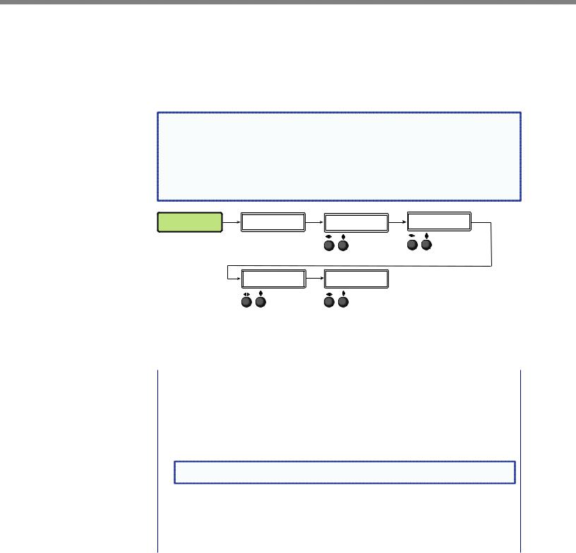
Audio Configuration (All Models)
Audio Configuration allows the user to set volume level (0 dB to -100 dB range), turn audio mute on or off, adjust input gain and attenuation levels (–53 dB to +9 dB range) for the current analog input. It also allows selection of an input audio format (none, analog, 2-channel digital, full digital, 2-channel auto, or full auto), and the audio output type (stereo or dual mono), which can be adjusted for each input.
NOTE: Volume level and input gain and attenuation adjustments are only available on |
|||||||
audio models (DVS 605 A and DVS 605 AD). |
|
|
|
||||
• For analog inputs 1 and 2, the choice of input audio format is analog or none. |
|||||||
• For non-audio models format selection for inputs 3 through 5 is limited to |
|||||||
none, 2-channel digital, or full digital. |
|
|
|
|
|||
• For inputs 3, 4, and 5, when in auto mode, digital audio is used when |
|
||||||
present. If no digital audio is present it defaults to analog audio. |
|
||||||
AUDIO |
Next |
VOLUME |
Next |
AUDIO MUTE |
Next |
IN4 GAIN/ATT |
Next |
CONFIG |
|
-75dB |
|
<OFF> ON |
|
0 dB |
|

 Rotate either to
 set volume level.
Next |
IN4 FORMAT |
Next |
|
DIGITAL |
|
|
Rotate either to |
|
|
select input |
|
|
audio format. |
|
Rotate either to turn audio mute on or off.
AUDIO OUTPUT
STEREO
Rotate either to select audio output format.
Rotate either to set gain and attenuation level.
Figure 17. Audio Configuration Menu
Use the Next button to scroll to the applicable submenu, and user both Adjust knobs ([ {) to change the settings as needed.
Input Audio |
Description |
Format |
|
|
|
None |
All audio for the input is muted: 128 byte EDID (VGA/DVI) is presented to the source. |
|
|
Analog |
5-pole captive screw connector is used for audio input: 128 byte EDID (VGA/DVI) is |
|
presented to the source. |
|
|
2-channel digital |
256 byte EDID (HDMI) is presented to the source requesting 2CH PCM audio. |
|
|
Full digital |
256 byte EDID (HDMI) is presented to the source allowing for all digital audio formats. |
|
|
NOTE: |
DVS 605 anlog audio outputs are active only if analog or PCM audio is detected on HDMI |
inputs 3,4, and 5. |
|
2-channel auto |
256 byte EDID (HDMI) is presented to the source requesting 2CH PCM audio. |
|
If digital audio is not present this automatically defaults to the 5-pole captive screw |
|
analog audio input. |
|
|
Full auto |
256 byte EDID (HDMI) is presented to the source allowing for all digital audio formats. |
|
If digital audio is not present this automatically defaults to the 5-pole captive screw |
|
analog audio input. |
|
|
Audio Delay Setting
The DVS automatically delays all analog and digital audio inputs to compensate for internal video processing delay. Occasionally additional audio delay is required to account for other signal processors, scalers, or display devices in a system. For these situations, the DVS 605 offers an additional 0-255 ms static global audio delay which can be set via SIS command or internal web pages to eliminate audio “lip sync” issues.
DVS 605 • Operation |
22 |
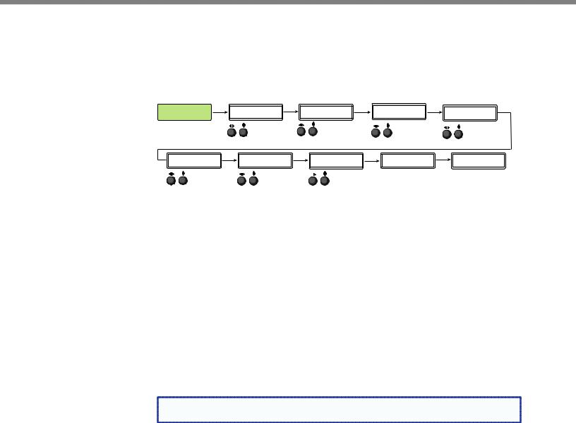
Advanced Configuration
The following flowchart provides an overview of the Advanced Configuration submenu The options are Auto-Image (on or off), aspect ratio (fill or follow), auto memory (on or off), overscan (none, 2.5%, and 5.0%), switch type (dissolve or cut), test patterns (see table on page 25), OSD duration, temperature (device reading only) and factory reset.
ADVANCED |
Next |
AUTO IMAGE |
Next |
CONFIG |
|
IN#x Off |
|
Rotate either to turn Auto Image mode on or off.
ASPECT RATIO |
Next |
AUTO MEMORY |
Next |
OVERSCAN |
Next |
|
IN#x |
FILL |
|
IN#x ON |
|
S-VIDEO 5.0% |
|
|
Rotate either to select |
Rotate either to |
|
Rotate either to set |
||
|
aspect ratio mode. |
turn auto memory |
overscan value. |
|||
|
|
|
on or off. |
|
|
|
SWITCH TYPE |
Next |
TEST PATTERN |
Next |
OSD DURATION |
Next |
TEMPERATURE |
Next |
FACT. RESET |
DISSOLVE |
|
COLOR BARS |
|
125 SEC |
|
96 F 35 C |
|
HOLD AUTO |
Rotate either to |
Rotate either to |
|
Rotate either to |
|
Indicates internal temperature |
Press and hold Auto button |
||
change switch |
change test pattern. |
set OSD duration. |
(not adjustable). |
|
to reset unit to factory settings. |
|||
type.
Figure 18. Advanced Configuration Menu
Aspect Ratio
Use either Adjust knob ([ {) to set the aspect ratio to Fill or Follow.
The aspect ratio setting is per input, and allows the user to select between each input signal filling the entire output raster (Fill - default setting), or for each input rate to be displayed with its native aspect ratio (Follow - 4:3, 5:4, 15:9, 16:9, 16:10) with the correct letter box or pillar box settings visible under the Image Size and Image Position Picture Controls.
When in the Fill mode, if an aspect ratio adjustment for a single input rate is desired, the correct size and center can be set up using Image Size and Image Position under Picture Controls, using one of the aspect ratio test patterns for a template. If auto memory is enabled, then these settings are saved and recalled the next time the signal is detected.
The DVS 605 clears the previous size and position settings whenever the aspect ratio setting for an input is adjusted.
NOTE: Unique SIS commands can set the device to Auto-Image and Fill or |
Auto-Image and Follow, regardless of the current aspect ratio. |
DVS 605 • Operation |
23 |

Auto-Image
Use either Adjust knob ([ {) to turn Auto-Image on or off (default).
When enabled and a new input frequency is detected, the DVS first applies an existing Auto Memory for the signal (if Auto Memory is enabled), or, if no entry exists, performs an automatic Auto-Image on the new signal. This automatically attempts to size/position the image to fill the screen, with respect to the current aspect ratio setting.
With Auto-Image disabled, the DVS 605 will apply default values to a new input if no Auto Memory exists (if Auto Memory is enabled).
Auto-Image threshold settings
By default, the Auto-Image function considers any analog video with a >25% brightness to be active video. Some video sources, such as dark PC backgrounds, or dark borders around a presentation, may require a lower “Auto-Image threshold,” to ensure incoming video is properly sized and centered by the Auto-Image function. Other scenarios, such as upstream analog twisted pair extension products, may require a greater Auto-Image Threshold setting in order to allow the DVS 605 to ignore extraneous sync pulses that may have been embedded in the RGB signals.
A global analog video Auto-Image threshold value can be set via an SIS command or using internal web pages.
The range is 0% (black / ~0.0 VDC) to 100% (white / ~0.7 VDC), with a default value of 25%.
NOTE: The Auto-Image threshold setting only affects analog input signals, and has no |
effect on digital inputs, which are sized and centered automatically. |
Auto Memory
Use either Adjust knob ([ {) to turn Auto Memory on (default) or off.
The DVS 605 stores 32 auto memories per input, with input configuration and picture control data for each input. The default settings enable these memories to automatically recall input and picture controls for signals that have been previously applied. When auto memories are disabled, the DVS treats every newly applied input as a new source. Default for Auto Memory is on.
How Auto Memory and Auto-Image Interact
Auto Memory |
Auto-Image |
Information |
|
|
|
On |
On |
“New” signals/rates that have not been previously detected by the DVS are initially |
|
|
set up using default parameters, then Auto-Image is automatically applied and values |
|
|
stored. The next time that signal is detected, the values stored in the auto memory |
|
|
location are applied. |
|
|
|
On |
Off |
“New” signals/rates that have not been previously detected by the DVS are set up using |
(Default) |
(Default) |
default parameters. If manual input and/or picture settings are made to the input, an |
|
|
auto memory location is created and recalled each successive time the input is detected. |
|
|
|
Off |
On |
Each change in input sync, input switch, or power cycle triggers an automatic Auto- |
|
|
Image. When auto memory is disabled, each change in sync is treated as a new signal |
|
|
and an automatic Auto-Image is triggered. Any manual changes made to the image and |
|
|
picture controls are lost each time a new rate is detected. |
|
|
|
Off |
Off |
Each change in input sync causes default values to be applied to the rate. Any manual |
|
|
changes made to the image and picture controls are lost when a new rate is applied. |
|
|
|
Figure 19. Auto Memory and Auto-Image Details
DVS 605 • Operation |
24 |
Loading...