


DP DA2
Table of contents
 Loading...
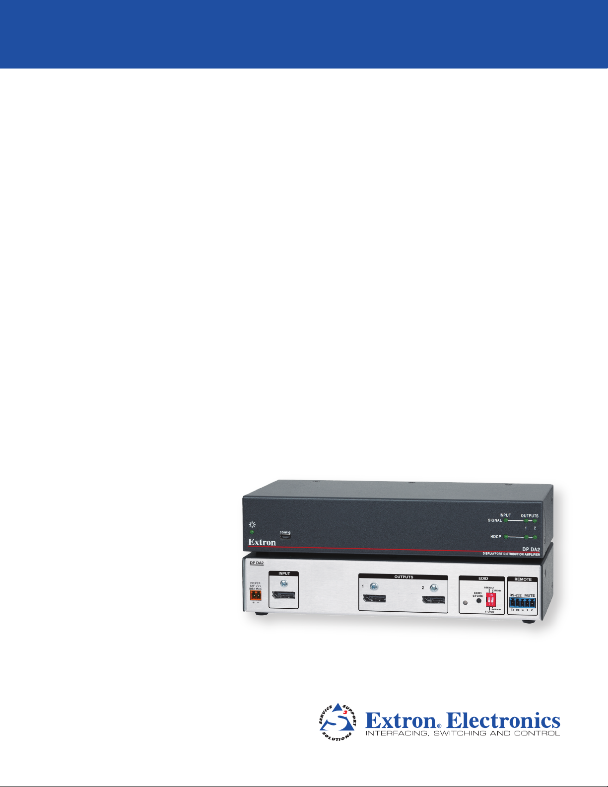
68-2154-01 Rev. B
10 12
DP DA2
User Guide
DisplayPort
Distribution Amplifier
Safety Instructions • English
WARNING: This symbol, D, when used on the product, is intended
to alert the user of the presence of uninsulated dangerous voltage
within the product’s enclosure that may present a risk of electric
shock.
ATTENTION: This symbol, I, when used on the product, is
intended to alert the user of important operating and maintenance
(servicing) instructions in the literature provided with the equipment.
For information on safety guidelines, regulatory compliances, EMI/EMF
compatibility, accessibility, and related topics, see the Extron Safety and
Regulatory Compliance Guide, part number 68-290-01, on the Extron
website, www.extron.com.
Instructions de sécurité • Français
AVERTISSEMENT: Ce pictogramme, D, lorsqu’il est utilisé sur le
produit, signale à l’utilisateur la présence à l’intérieur du boîtier
du produit d’une tension électrique dangereuse susceptible de
provoquer un choc électrique.
ATTENTION: Ce pictogramme, I, lorsqu’il est utilisé sur le produit,
signale à l’utilisateur des instructions d’utilisation ou de maintenance
importantes qui se trouvent dans la documentation fournie avec le
matériel.
Pour en savoir plus sur les règles de sécurité, la conformité à la
réglementation, la compatibilité EMI/EMF, l’accessibilité, et autres sujets
connexes, lisez les informations de sécurité et de conformité Extron,
réf. 68-290-01, sur le site Extron, www.extron.fr.
Sicherheitsanweisungen • Deutsch
WARNUNG: Dieses Symbol D auf dem Produkt soll den Benutzer
darauf aufmerksam machen, dass im Inneren des Gehäuses dieses
Produktes gefährliche Spannungen herrschen, die nicht isoliert sind
und die einen elektrischen Schlag verursachen können.
VORSICHT: Dieses Symbol I auf dem Produkt soll dem Benutzer in
der im Lieferumfang enthaltenen Dokumentation besonders wichtige
Hinweise zur Bedienung und Wartung (Instandhaltung) geben.
Weitere Informationen über die Sicherheitsrichtlinien, Produkthandhabung,
EMI/EMF-Kompatibilität, Zugänglichkeit und verwandte Themen finden Sie
in den Extron-Richtlinien für Sicherheit und Handhabung (Artikelnummer
68-290-01) auf der Extron-Website, www.extron.de.
Instrucciones de seguridad • Español
ADVERTENCIA: Este símbolo, D, cuando se utiliza en el producto,
avisa al usuario de la presencia de voltaje peligroso sin aislar dentro
del producto, lo que puede representar un riesgo de descarga
eléctrica.
ATENCIÓN: Este símbolo, I, cuando se utiliza en el producto, avisa
al usuario de la presencia de importantes instrucciones de uso y
mantenimiento recogidas en la documentación proporcionada con
el equipo.
Para obtener información sobre directrices de seguridad, cumplimiento
de normativas, compatibilidad electromagnética, accesibilidad y
temas relacionados, consulte la Guía de cumplimiento de normativas
y seguridad de Extron, referencia 68-290-01, en el sitio Web de Extron,
www.extron.es.
Chinese Simplified(简体中文)
警告:D产品上的这个标志意在警告用户该产品机壳内有暴露的危险
电 压 ,有 触 电 危 险 。
注意:I 产品上的这个标志意在提示用户设备随附的用户手册中有
重要的操作和维护(维修)说明。
关于我们产品的安全指南、遵循的规范、
EMI/EMF 的兼容性、无障碍
使用的特性等相关内容,敬请访问
Extron 网站 www.extron.com,参见 Extron
安全规范指南,产品编号
68-290-01。
Chinese Traditional(繁體中文)
警告: D若產品上使用此符號,是為了提醒使用者,產品機殼內存在著
可能會導致觸電之風險的未絕緣危險電壓。
注意I 若產品上使用此符號,是為了提醒使用者。
有關安全性指導方針、法規遵守、EMI/EMF 相容性、存取範圍和相關主題的詳細
資訊,請瀏覽 Extron 網站:www.extron.com,然後參閱《Extron 安全性與法
規遵守手冊》,準則編號 68-290-01。
Japanese
警告: この記号 D が製品上に表示されている場合は、筐体内に絶縁されて
いない高電圧が流れ、感電の危険があることを示しています。
注意: この記 号 I が製品上に表 示されている場合は、本機の取扱 説明書に記載されて
いる重要な操 作と保 守( 整備 )の 指示に ついてユーザーの注 意を喚 起するものです。
安全上のご注意、法令遵守、EMI/EMF適合性、その他の関連項目に
つ い て は 、エク スト ロン の ウ ェ ブ サ イト www.extron.comより
『Extron Safety and Regulatory Compliance Guide』 (P/N 68-290-01) をご覧く
ださい。
Korean
경고: 이 기호 D, 가 제품에 사용될 경우, 제품의 인클로저 내에 있는
접지되지 않은 위험한 전류로 인해 사용자가 감전될 위험이 있음을
경고합니다.
주의: 이 기호 I, 가 제품에 사용될 경우, 장비와 함께 제공된 책자에 나와
있는 주요 운영 및 유지보수(정비) 지침을 경고합니다.
안전 가이드라인, 규제 준수, EMI/EMF 호환성, 접근성, 그리고 관련
항목에 대한 자세한 내용은 Extron 웹 사이트(www.extron.com)의
Extron 안전 및 규제 준수 안내서, 68-290-01 조항을 참조하십시오.
Safety Instructions

FCC Class A Notice
This equipment has been tested and found to comply with the limits for a Class A digital
device, pursuant to part 15 of the FCC Rules. Operation is subject to the following two
conditions:
1. This device may not cause harmful interference.
2. This device must accept any interference received, including interference that may
cause undesired operation.
The Class A limits are designed to provide reasonable protection against harmful
interference when the equipment is operated in a commercial environment. This equipment
generates, uses, and can radiate radio frequency energy and, if not installed and used in
accordance with the user guide, may cause harmful interference to radio communications.
Operation of this equipment in a residential area is likely to cause harmful interference, in
which case the user will be required to correct the interference at his own expense.
NOTE: This unit was tested with shielded cables on the peripheral devices. Shielded
cables must be used with theunit to ensure compliance with FCC emissions
limits.
For more information on safety guidelines, regulatory compliances, EMI/EMF
compliance, accessibility, and related topics, click here.
Specifications Availability
Product specifications are available on the Extron website, www.extron.com.
Copyright
© 2012 Extron Electronics. All rights reserved.
Trademarks
All trademarks mentioned in this guide are the properties of their respective owners
Conventions Used in this Guide
Notifications the following are used:
ATTENTION: Attention indicates a situation that may damage or destroy the product
or associated equipment.
NOTE: A note draws attention to important information.
TIP: A tip provides a suggestion to make working with the application easier.
Software Commands
Commands are written in the fonts shown here:
^AR Merge Scene,,Op1 scene 1,1 ^B 51 ^W^C
[01] R 0004 00300 00400 00800 00600 [02] 35 [17] [03]
E X! *X1&* X2)* X2#* X2! CE}
NOTE: For commands and examples of computer or device responses
mentioned in this guide, the character “0” is used for the number zero and
“O” represents the capital letter “o.”
Computer responses and directory paths that do not have variables are written in the
font shown here:
Reply from 208.132.180.48: bytes=32 times=2ms TTL=32
C:\Program Files\Extron
Variables are written in slanted form as shown here:
ping xxx.xxx.xxx.xxx —t
SOH R Data STX Command ETB ETX
Selectable items, such as menu names, menu options, buttons, tabs, and field names
are written in the font shown here:
From the File menu, select New.
Click the OK button.

Contents
Safety Instructions ....................................... ii
Introduction............................................................ 1
About the DP DA2 .............................................. 1
DP DA2 Features ................................................ 1
Application Diagram ........................................... 2
Panel Features ........................................................ 3
Rear Panel .......................................................... 3
Front Panel ......................................................... 3
Rear Panel Features ........................................... 4
Power Supply ................................................. 4
Display Port Connectors ................................. 5
Dual Mode DisplayPort ................................... 6
EDID Minder ................................................... 6
RS-232 Control .............................................. 8
Mute Control................................................... 8
Front Panel Features ........................................... 9
Power LED ..................................................... 9
Config USB Port ............................................. 9
Signal and HDCP LEDs ................................ 11
Setup ...................................................................... 12
SIS Commands ..................................................... 13
Introduction to SIS ........................................... 13
Symbols Used in this Guide .............................. 14
Error Messages ................................................ 14
Command and Response Table for SIS
Commands ..................................................... 15
Updating Firmware ............................................. 16
Downloading and Installing Firmware Loader .... 16
Downloading DP DA2 Firmware ........................ 17
Loading the Firmware to the DP DA2 ................ 18
Resetting Firmware to the
Factory Default Version .................................... 21
Reference Information ....................................... 22
Included Parts .................................................. 22
Optional Parts................................................... 22
Mounting .............................................................. 23
Desktop Placement .......................................... 23
Rack Mounting ................................................. 23
UL Guidelines for Rack Mounting .................. 23
Rack Mounting Procedure ............................ 23
DP DA2 • Contents v

DP DA2 • Contents vi

Introduction
This guide describes the function, installation and operation of the DP DA2 distribution
amplifier. Unless otherwise stated, the terms “DA” and “distribution amplifier” refer to the
DPDA2.
This section contains the following information:
• About the DP DA2
• DP DA2 Features
• Application Diagram
About the DP DA2
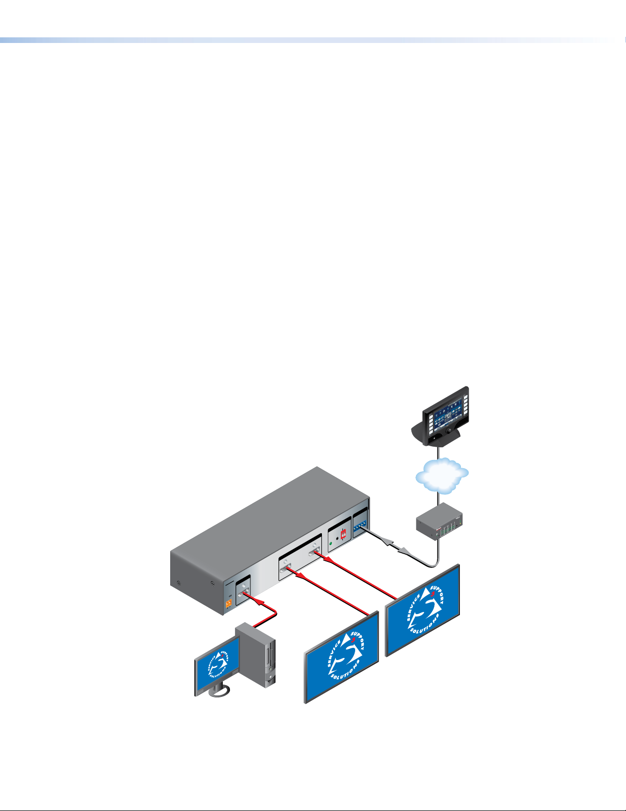
The DP DA2 provides an Extron distribution amplifier for VESA
®
DisplayPort signals. It
accepts a single input with data rates up to 10.8 Gbps and, in normal mode, distributes
two identical outputs with resolutions of up to 2560x1600 @ 60 Hz on each output. Input
and output signals can each be carried a maximum of 25feet (7.62 m).
In Extend mode, the DP DA2 outputs an image with a resolution of up to
3840x1080@60Hz extended over two output displays.
The DP DA2 uses the DisplayPort v1.1a standard and is backwards compatible with
earlier specifications. It has EDID Minder
®
for EDID management, Key Minder
®
for
continuous HDCP verification, and can be controlled by RS-232, using the Extron Simple
Instruction Set (SIS
™
) commands.
DP DA2 Features
DisplayPort — In normal mode provides two identical outputs with PC resolutions
up to 2560x1600 @ 60 Hz, with multi-channel audio and HDTV up to 1080p @ 60 Hz,
distributed with embedded multi-channel digital audio signals.
Thunderbolt
™
source support (input) — Thunderbolt sources are backward
compatible with the DPDA2 input with respect to both audio and video. Thunderbolt
devices are not supported on the DPDA2 outputs.
Signals up to 10.8 Gbps — Supports data rates of either 1.62Gbps (reduced bit rate)or
2.7 Gbps (high bit rate) using one, two, or four lanes.
Dual mode — Allows for interoperability with HDMI, DVI, and VGA display devices.
Provides connectivity between a dual mode DisplayPort-equipped source and HDMI, DVI,
and VGA display devices with an appropriate adapter.
Extend mode — Outputs a single image with a resolution of up to 3840x1080 @ 60 Hz
extended over two output displays.
EDID Minder
®
— Maintains continuous EDID (Extended Display Identification Data)
communication with the attached source. This ensures that the source powers up
correctly and maintains a proper video output, even if the display is off.
Content protection — Supports High-bandwidth Digital Content Protection (HDCP). The
DPDA2 checks the source and output displays for HDCP compliance.
DP DA2 • Introduction 1
HDCP visual confirmation — Provides a green signal when encrypted content is sent to
a non-compliant display. A full-screen green signal is sent when HDCP-encrypted content
is transmitted to a non-HDCP compliant display, providing immediate visual confirmation
that protected content cannot be viewed on the display.
Key Minder
®
— Authenticates and maintains continuous HDCP encryption between all
input and output devices to enable simultaneous distribution of a single source signal to
two or more displays.
Automatic input cable equalization — Up to 25 feet (7.6 meters) at 2560x1600 @ 60
Hz with Extron DisplayPort cables. Conditions incoming digital signals to compensate for
signal loss from long cables, low quality cables, or source devices with poor DisplayPort
signal output.
LED indicators — Provide real-time feedback and monitoring of key performance
parameters by indicating signal presence and HDCP authentication. The tri-color EDID
LED indicator on the back panel shows whether an internal or external EDID is stored.
RS-232 serial control — Allows control by SIS
™
commands either via the controller or
directly from a PC using the front panel USB port or the rear panel 3-pole captive screw
connector.
Output muting control via RS-232 or contact closure — Provides the capability to
mute one or both outputs at any time. This allows content to be viewed on a local monitor
prior to appearing on the main presentation display.
Application Diagram
12V
0.6A MAX
POWER
EDID
STORE
EXTEND
NORMAL
DEFAULT
STORED
1
RS-232 MUTE
RxTx 1G 2
2
INPUT
REMOTE
EDID
OUTPUTS
DP DA2
Flat Panel Displays
with DisplayPort Inputs
Extron
DP DA2
DisplayPort
Distribution
Amplier
PC with DisplayPor t Output
1
3
1
4
2
31
42
3
1
4
2
2
3
100
LINK
ACT
COM
IR
INPUT
RELAY
TX
RX
R
IPL 250
®
ON
OFF
DISPLAY
MUTE
SCREEN
UP
SCREEN
DOWN
VCR
DVD
DOC
CAM
LAPTOP
PC
TCP/IP
TouchLink
Control
System
Figure 1. Typical DP DA2 Application
DP DA2 • Introduction 2
Panel Features
This section describes the panel features and connections of the DP DA2.
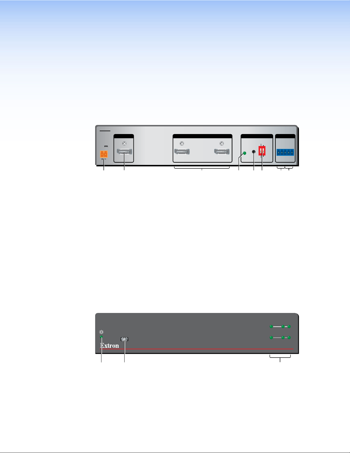
Rear Panel
12V
0.6A MAX
POWER
EDID
STORE
EXTEND
NORMAL
DEFAULT
STORED
1
RS-232 MUTE
RxTx 1G2
2
INPUT REMOTEEDIDOUTPUTS
DP DA2
ab cdef gh
Figure 2. DP DA2 Rear Panel
a
Power — Connect the provided power supply to this 2-pole, 3.5 mm captive screw
connector.
b
Input — Connect the source device to this female DisplayPort connector.
c
Outputs — Connect up to two display devices to these female DisplayPort
connectors.
d
EDID Minder LED — Lights red, amber, or green, showing current EDID Minder
state.
e
EDID Minder Store push button — This recessed button activates EDID store.
f
EDID Minder DIP switches — Used to configure the EDID Minder features.
g
RS-232 control — Connect the transmit (Tx), receive (Rx), and ground (G)
connectors of this 5-pole, 3.5 mm captive screw connector to a control PC.
h
Mute control — Connect the ground (G) and either pin 1 (to mute output1) or pin 2
(to mute channel 2).
Front Panel
DP DA2
DISPLAYPORT DISTRIBUTION AMPLIFIER
INPUT
OUTPUTS
12
SIGNAL
HDCP
CONFIG
i j k
Figure 3. DP DA2 Front Panel
i
Power LED — Lights green when the unit is receiving power.
j
Config USB port — Connect this USB port to a control PC.
k
Signal and HDCP LEDs — Provide information about the signal and HDCP
encryption status of the input and outputs.
DP DA2 • Panel Features 3
Loading...