


 Loading...
User’s Manual
|
|
|
|
|
|
|
|
|
|
|
|
|
DVI 201 Tx/Rx |
|
|
|
|
|
|
|
|
|
|
|
|
|
Digital Video Transmitter and Receiver |
Extron USA - West |
|
Extron USA - East |
|
Extron Europe |
|
Extron Asia |
|
Extron Japan |
|
Extron China |
|
Extron Dubai |
|
|
|
|
|
|
|
|
|||||||
Headquarters |
|
+800.633.9876 |
|
+800.3987.6673 |
|
+800.7339.8766 |
|
+81.3.3511.7655 |
|
+400.883.1568 |
|
+971.4.2991800 |
68-1034-02 Rev. B |
|
|
|
|
|
|
|
|||||||
+800.633.9876 |
|
Inside USA / Canada Only |
|
Inside Europe Only |
|
Inside Asia Only |
|
+81.3.3511.7656 FAX |
|
Inside China Only |
|
+971.4.2991880 FAX |
08 08 |
Inside USA / Canada Only |
|
+1.919.863.1794 |
|
+31.33.453.4040 |
|
+65.6383.4400 |
|
|
|
+86.21.3760.1568 |
|
|
|
|
|
|
|
|
|
|
|
|
|
||||
+1.714.491.1500 |
|
+1.919.863.1797 FAX |
|
+31.33.453.4050 FAX |
|
+65.6383.4664 FAX |
|
|
|
+86.21.3760.1566 FAX |
|
|
|
+1.714.491.1517 FAX |
|
|
|
|
|
|
|
|
|
|
|
|
|
© 2008 Extron Electronics. All rights reserved.

Precautions
Safety Instructions • English
Thissymbolisintendedtoalerttheuserofimportant operatingandmaintenance(servicing)instructionsin the literature provided with the equipment.
This symbol is intended to alert the user of the presence of uninsulated dangerous voltage within the product’s enclosure that may present a risk of electric shock.
Caution
Read Instructions • Read and understand all safety and operating instructions before using the equipment.
Retain Instructions • The safety instructions should be kept for future reference.
Follow Warnings • Follow all warnings and instructions marked on the equipment or in the user information.
Avoid Attachments • Do not use tools or attachments that are not recommended by the equipment manufacturer because they may be hazardous.
Warning
Power sources • This equipment should be operated only from the power source indicated on the product. This equipment is intended to be used with a main power system with a grounded (neutral) conductor. The third (grounding) pin is a safety feature, do not attempt to bypass or disable it.
Power disconnection • To remove power from the equipment safely, remove all power cords from the rear of the equipment, or the desktop power module (if detachable), or from the power source receptacle (wall plug).
Power cord protection • Power cords should be routed so that they are not likely to be stepped on or pinched by items placed upon or against them.
Servicing • Refer all servicing to qualified service personnel. There are no userserviceable parts inside. To prevent the risk of shock, do not attempt to service this equipment yourself because opening or removing covers may expose you to dangerous voltage or other hazards.
Slots and openings • If the equipment has slots or holes in the enclosure, these are provided to prevent overheating of sensitive components inside. These openings must never be blocked by other objects.
Lithium battery • There is a danger of explosion if battery is incorrectly replaced. Replace it only with the same or equivalent type recommended by the manufacturer. Dispose of used batteries according to the manufacturer’s instructions.
Consignes de Sécurité • Français
Ce symbole sert à avertir l’utilisateur que la documentation fournie avec le matériel contient des instructionsimportantesconcernantl’exploitationet la maintenance (réparation).
Ce symbole sert à avertir l’utilisateur de la présence dansleboîtierdel’appareilde tensionsdangereuses non isolées posant des risques d’électrocution.
Attention
Lire les instructions• Prendre connaissance de toutes les consignes de sécurité et d’exploitation avant d’utiliser le matériel.
Conserver les instructions• Ranger les consignes de sécurité afin de pouvoir les consulter à l’avenir.
Respecter les avertissements • Observer tous les avertissements et consignes marqués sur le matériel ou présentés dans la documentation utilisateur.
Eviter les pièces de fixation • Ne pas utiliser de pièces de fixation ni d’outils non recommandés par le fabricant du matériel car cela risquerait de poser certains dangers.
Avertissement
Alimentations• Ne faire fonctionner ce matériel qu’avec la source d’alimentation indiquée sur l’appareil. Ce matériel doit être utilisé avec une alimentation principale comportant un fil de terre (neutre). Le troisième contact (de mise à la terre) constitue un dispositif de sécurité : n’essayez pas de la contourner ni de la désactiver.
Déconnexion de l’alimentation• Pour mettre le matériel hors tension sans danger, déconnectez tous les cordons d’alimentation de l’arrière de l’appareil ou du module d’alimentation de bureau (s’il est amovible) ou encore de la prise secteur.
Protection du cordon d’alimentation • Acheminer les cordons d’alimentation de manière à ce que personne ne risque de marcher dessus et à ce qu’ils ne soient pas écrasés ou pincés par des objets.
Réparation-maintenance • Faire exécuter toutes les interventions de réparationmaintenance par un technicien qualifié. Aucun des éléments internes ne peut être réparé par l’utilisateur. Afin d’éviter tout danger d’électrocution, l’utilisateur ne doit pas essayer de procéder lui-même à ces opérations car l’ouverture ou le retrait des couvercles risquent de l’exposer à de hautes tensions et autres dangers.
Fentes et orifices • Si le boîtier de l’appareil comporte des fentes ou des orifices, ceux-ci servent à empêcher les composants internes sensibles de surchauffer. Ces ouvertures ne doivent jamais être bloquées par des objets.
Lithium Batterie • Il a danger d’explosion s’ll y a remplacment incorrect de la batterie. Remplacer uniquement avec une batterie du meme type ou d’un ype equivalent recommande par le constructeur. Mettre au reut les batteries usagees conformement aux instructions du fabricant.
Sicherheitsanleitungen • Deutsch
Dieses Symbol soll dem Benutzer in der im Lieferumfang enthaltenen Dokumentation besonders wichtige Hinweise zur Bedienung und Wartung (Instandhaltung) geben.
DiesesSymbolsolldenBenutzerdaraufaufmerksam machen, daß im Inneren des Gehäuses dieses ProduktesgefährlicheSpannungen,dienichtisoliert sind und die einen elektrischen Schock verursachen können, herrschen.
Achtung
Lesen der Anleitungen • Bevor Sie das Gerät zum ersten Mal verwenden, sollten Sie alle Sicherheits-und Bedienungsanleitungen genau durchlesen und verstehen.
Aufbewahren der Anleitungen • Die Hinweise zur elektrischen Sicherheit des Produktes sollten Sie aufbewahren, damit Sie im Bedarfsfall darauf zurückgreifen können.
Befolgen der Warnhinweise • Befolgen Sie alle Warnhinweise und Anleitungen auf dem Gerät oder in der Benutzerdokumentation.
Keine Zusatzgeräte • Verwenden Sie keine Werkzeuge oder Zusatzgeräte, die nicht ausdrücklich vom Hersteller empfohlen wurden, da diese eine Gefahrenquelle darstellen können.
Instrucciones de seguridad • Español
Este símbolo se utiliza para advertir al usuario sobre instrucciones importantes de operación y mantenimiento (o cambio de partes) que se desean destacar en el contenido de la documentación suministrada con los equipos.
Este símbolo se utiliza para advertir al usuario sobre la presencia de elementos con voltaje peligroso sin protección aislante, que puedan encontrarse dentro de la caja o alojamiento del producto, y que puedan representar riesgo de electrocución.
Precaucion
Leer las instrucciones • Leer y analizar todas las instrucciones de operación y seguridad, antes de usar el equipo.
Conservar las instrucciones • Conservar las instrucciones de seguridad para futura consulta.
Obedecer las advertencias • Todas las advertencias e instrucciones marcadas en el equipo o en la documentación del usuario, deben ser obedecidas.
Evitar el uso de accesorios • No usar herramientas o accesorios que no sean especificamente recomendados por el fabricante, ya que podrian implicar riesgos.
Vorsicht
Stromquellen • Dieses Gerät sollte nur über die auf dem Produkt angegebene Stromquelle betrieben werden. Dieses Gerät wurde für eine Verwendung mit einer Hauptstromleitung mit einem geerdeten (neutralen) Leiter konzipiert. Der dritte
Kontakt ist für einen Erdanschluß, und stellt eine Sicherheitsfunktion dar. Diese sollte nicht umgangen oder außer Betrieb gesetzt werden.
Stromunterbrechung • Um das Gerät auf sichere Weise vom Netz zu trennen, sollten Sie alle Netzkabel aus der Rückseite des Gerätes, aus der externen Stomversorgung (falls dies möglich ist) oder aus der Wandsteckdose ziehen.
Schutz des Netzkabels • Netzkabel sollten stets so verlegt werden, daß sie nicht im Weg liegen und niemand darauf treten kann oder Objekte daraufoder unmittelbar dagegengestellt werden können.
Wartung • Alle Wartungsmaßnahmen sollten nur von qualifiziertem Servicepersonal durchgeführt werden. Die internen Komponenten des Gerätes sind wartungsfrei. Zur Vermeidung eines elektrischen Schocks versuchen Sie in keinem Fall, dieses Gerät selbst öffnen, da beim Entfernen der Abdeckungen die Gefahr eines elektrischen Schlags und/oder andere Gefahren bestehen.
Schlitze und Öffnungen • Wenn das Gerät Schlitze oder Löcher im Gehäuse aufweist, dienen diese zur Vermeidung einer Überhitzung der empfindlichen Teile im
Inneren. Diese Öffnungen dürfen niemals von anderen Objekten blockiert werden.
Litium-Batterie • Explosionsgefahr, falls die Batterie nicht richtig ersetzt wird. Ersetzen Sie verbrauchte Batterien nur durch den gleichen oder einen
vergleichbaren Batterietyp, der auch vom Hersteller empfohlen wird. Entsorgen Sie verbrauchte Batterien bitte gemäß den Herstelleranweisungen.
Advertencia
Alimentación eléctrica • Este equipo debe conectarse únicamente a la fuente/tipo de alimentación eléctrica indicada en el mismo. La alimentación eléctrica de este equipo debe provenir de un sistema de distribución general con conductor neutro
a tierra. La tercera pata (puesta a tierra) es una medida de seguridad, no puentearia ni eliminaria.
Desconexión de alimentación eléctrica • Para desconectar con seguridad la acometida de alimentación eléctrica al equipo, desenchufar todos los cables de alimentación en el panel trasero del equipo, o desenchufar el módulo de alimentación (si fuera independiente), o desenchufar el cable del receptáculo de la pared.
Protección del cables de alimentación • Los cables de alimentación eléctrica se deben instalar en lugares donde no sean pisados ni apretados por objetos que se puedan apoyar sobre ellos.
Reparaciones/mantenimiento • Solicitar siempre los servicios técnicos de personal calificado. En el interior no hay partes a las que el usuario deba acceder. Para evitar riesgo de electrocución, no intentar personalmente la reparación/mantenimiento de este equipo, ya que al abrir o extraer las tapas puede quedar expuesto a voltajes peligrosos u otros riesgos.
Ranuras y aberturas • Si el equipo posee ranuras o orificios en su caja/alojamiento, es para evitar el sobrecalientamiento de componentes internos sensibles. Estas aberturas nunca se deben obstruir con otros objetos.
Batería de litio • Existe riesgo de explosión si esta batería se coloca en la posición incorrecta. Cambiar esta batería únicamente con el mismo tipo (o su equivalente) recomendado por el fabricante. Desachar las baterías usadas siguiendo las instrucciones del fabricante.
Extron’s Warranty
Extron Electronics warrants this product against defects in materials and workmanship for a period of three years from the date of purchase. In the event of malfunction during the warranty period attributable directly to faulty workmanship and/or materials, Extron Electronics will, at its option, repair or replace said products or components,
to whatever extent it shall deem necessary to restore said product to proper operating condition, provided that it is returned within the warranty period, with proof of purchase and description of malfunction to:
USA, Canada, South America, |
Europe, Africa, and the Middle East: |
and Central America: |
Extron Electronics, Europe |
Extron Electronics |
Beeldschermweg 6C |
1001 East Ball Road |
3821 AH Amersfoort |
Anaheim, CA 92805, USA |
The Netherlands |
Asia: |
Japan: |
Extron Electronics, Asia |
Extron Electronics, Japan |
135 Joo Seng Road, #04-01 |
Kyodo Building |
PM Industrial Bldg. |
16 Ichibancho |
Singapore 368363 |
Chiyoda-ku, Tokyo 102-0082 |
|
Japan |
This Limited Warranty does not apply if the fault has been caused by misuse, improper handling care, electrical or mechanical abuse, abnormal operating conditions or nonExtron authorized modification to the product.
If it has been determined that the product is defective, please call Extron and ask for an Applications Engineer at (714) 491-1500 (USA), 31.33.453.4040 (Europe), 65.6383.4400 (Asia), or 81.3.3511.7655 (Japan) to receive an RA# (Return Authorization number). This will begin the repair process as quickly as possible.
Units must be returned insured, with shipping charges prepaid. If not insured, you assume the risk of loss or damage during shipment. Returned units must include the serial number and a description of the problem, as well as the name of the person to contact in case there are any questions.
Extron Electronics makes no further warranties either expressed or implied with respect to the product and its quality, performance, merchantability, or fitness for any particular use. In no event will Extron Electronics be liable for direct, indirect, or consequential damages resulting from any defect in this product even if Extron Electronics has been advised of such damage.
Please note that laws vary from state to state and country to country, and that some provisions of this warranty may not apply to you.

•
有重要的操作和维护说明。

•
•
•
•
•
•
••
•
•
FCC Class A Notice
This equipment has been tested and found to comply with the limits for a Class A digital device, pursuant to part 15 of the FCC Rules. Operation is subject to the following two conditions: (1) this device may not cause harmful interference, and (2) this device must accept any interference received, including interference that may cause undesired operation. The Class A limits are designed to provide reasonable protection against harmful interference when the equipment is operated in a commercial environment. This equipment generates, uses, and can radiate radio frequency energy and, if not installed and used in accordance with the instruction manual, may cause harmful interference to radio communications. Operation of this equipment in a residential area is likely to cause harmful interference, in which case the user will be required to correct the interference at his own expense.
NThis unit was tested with shielded cables on the peripheral devices. Shielded cables must be used with the unit to ensure compliance with FCC emissions limits.

Table of Contents
Chapter One • Introduction..................................................... |
1-1 |
About this Manual..................................................................... |
1-2 |
About the DVI 201 Transmitters and Receivers................ |
1-2 |
TP cable advantages............................................................... |
1-4 |
Control communications........................................................ |
1-4 |
Transmission distance............................................................ |
1-4 |
Features......................................................................................... |
1-5 |
Chapter Two • Installation and Operation................... |
2-1 |
Mounting the Tx/Rx.................................................................. |
2-2 |
Non-Decora unit mounting.................................................... |
2-2 |
Tabletop placement............................................................ |
2-2 |
Rack mounting................................................................... |
2-2 |
Under-furniture mounting.................................................. |
2-4 |
Through-furniture mounting.............................................. |
2-5 |
Projector mounting............................................................ |
2-6 |
Decora unit mounting.......................................................... |
2-11 |
UL/Safety Requirements................................................... |
2-11 |
Preparing the site and installing the wall box.................. |
2-11 |
Final installation............................................................... |
2-14 |
Connections................................................................................ |
2-15 |
Transmitter connections....................................................... |
2-15 |
Receiver connections............................................................ |
2-19 |
Pin assignments and wiring................................................. |
2-22 |
DVI connector pin assignments........................................ |
2-22 |
TP cable termination......................................................... |
2-23 |
Power supply wiring........................................................ |
2-25 |
RS-232 connector wiring.................................................. |
2-26 |
Operation.................................................................................... |
2-27 |
Transmitter control and indicator........................................ |
2-29 |
Receiver indicator................................................................. |
2-29 |
System operation................................................................. |
2-29 |
Technical Points for Digital Video and Content |
|
Protection Encryption............................................................. |
2-30 |
Troubleshooting........................................................................ |
2-31 |
Application Examples............................................................. |
2-32 |
Audio conversion.................................................................. |
2-32 |
Modulated IR pass through................................................. |
2-33 |
DVI 201 Tx/Rx • Table of Contents |
i |

Table of Contents, cont’d
Appendix A • Reference Information.............................. |
A-1 |
Specifications............................................................................... |
A-2 |
Part Numbers............................................................................... |
A-6 |
Transmitter/receiver pair part numbers................................ |
A-6 |
Included parts......................................................................... |
A-6 |
Mounting accessories............................................................. |
A-7 |
Cables...................................................................................... |
A-8 |
Adapters.................................................................................. |
A-8 |
Decora Template Dimensions................................................. |
A-9 |
68-1034-02 Rev. B
08 08
All trademarks mentioned in this manual are the properties of their respective owners.

 DVI 201 Tx/Rx
Chapter1One
Introduction
About this Manual
About the DVI 201 Transmitters and Receivers
Features
ii DVI 201 Tx/Rx • Table of Contents
Introduction
About this Manual
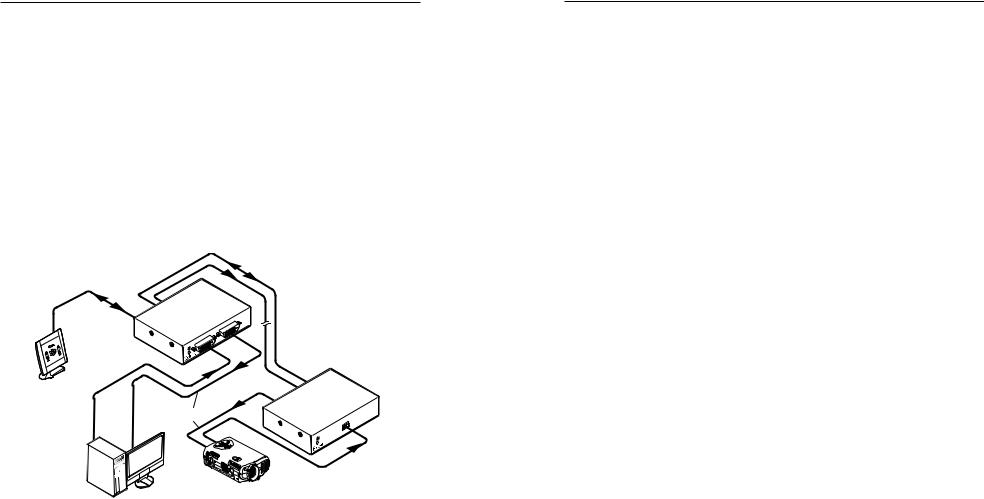
This manual contains information about the Extron DVI 201 family of Digital Visual Interface (DVI) video
transmitters (Tx) and receivers (Rx), including how to install, operate, and configure them.
About the DVI 201 Transmitters and Receivers
The Extron DVI 201 is a family of DVI transmitters and receivers, in enclosures that support different mounting options. A transmitter and receiver pair extends the usable distance of DVI digital video and RS-232 control signals over two Category (CAT) 5/5e/6 unshielded twisted pair (UTP) or shielded twisted pair (STP) cables. The DVI 201 A D transmitter and receiver also route audio, but not on the TP link. The video and control (and audio, if applicable) signals can be transmitted up to 200' (60 m).
Extron
DVI 201 Tx
Transmitter
RS-232
Control
DVI Cable
Multimedia
PC
SER |
IES |
|
Projector
 CAT 5/5e/6/7 UTP up to 200’
Extron
DVI 201 Rx
er
DVI |
20 |
0 |
|
||
|
|
RS-23THRU2
PASS
Tx Rx |
 RS-232
Figure1-1—Typicaltransmitterandreceiverapplication
A DVI 201 system consists of a transmitter (Tx) and a receiver (Rx). The pair can handle a single link of DVI-D digital video and a bi-directional RS-232 link. The DVI 201 A D also converts a computer audio input into balanced or unbalanced stereo audio output.
There are two subsets of transmitters and receivers in two different enclosures or form factors:
•DVI 201 Tx/Rx — These units are housed in quarter rack width metal enclosures. They can be set on a tabletop or mounted in a rack, under or through furniture, or to a projector pole. The transmitter in this form factor has a local monitor output.
NThe non-Decora® models do not input, transmit, receive, or output audio.
•DVI 201 A D Tx/Rx — These units are housed in enclosures that can be mounted in UL standard wall boxes with Decora-style face plates. These units also convert computer level audio to balanced or unbalanced stereo audio.
N• A non-Decora transmitter or receiver is partially compatible with a Decora receiver or transmitter.
•A mixed form factor system can transmit and receive video and RS-232 communications.
•A mixed form factor system cannot handle audio, as the non-Decora models do not input, transmit, receive, or output audio.
|
|
Transmitters |
Receivers |
||||
|
|
DVI 201 Tx |
|
DVI 201 A D Tx |
DVI 201 Rx |
|
DVI 201 A D Rx |
|
|
|
|
||||
|
|
non-Decora |
|
Decora |
non-Decora |
|
Decora |
|
|
|
|
|
|
|
|
Transmitters |
DVI 201 Tx |
|
|
|
DVI video |
|
DVI video |
non-Decora |
|
|
|
Control |
|
Control |
|
|
|
|
|
|
|||
|
|
|
|
|
|
|
|
|
DVI 201 A D Tx |
|
|
|
DVI video |
|
DVI video |
|
non-Decora |
|
|
|
Control |
|
Control |
|
|
|
|
|
|
|
Audio (pass) |
Receivers |
DVI 201 Rx |
DVI video |
|
DVI video |
|
|
|
non-Decora |
Control |
|
Control |
|
|
|
|
|
non-Decora |
Control |
|
Control |
|
|
|
|
DVI 201 A D Rx |
DVI video |
|
DVI video |
|
|
|
|
|
|
|
Audio (pass) |
|
|
|
|
|
|
|
|
|
|
|
The units can be purchased as a pair (of the same form factor) or individually. Each purchased pair and each individual transmitter is shipped with a single external desktop 12 VDC power supply that accepts 100 to 240 VAC, 50 Hz or 60 Hz input. A single power supply connected to either the transmitter or the receiver can power both units through one of the TP cables that link the units.
1-2 |
DVI 201 Tx/Rx • Introduction |
DVI 201 Tx/Rx • Introduction |
1-3 |

Introduction, cont’d
NIn this manual, the terms "DVI 201," "DVI 201 Tx," "DVI 201 Rx," "transmitter," and "receiver" refer to the applicable unit(s) in either form factor, unless otherwise specified.
TP cable advantages
Twisted pair cable is much smaller, lighter, more flexible, and less expensive than coaxial or DVI cable. These transmitter and receiver twisted pair (TP) products make cable runs simpler and less cumbersome. Termination of the cable with RJ-45 connectors is simple, quick, and economical.
NThe transmitter and receiver pair works with unshielded twisted pair (UTP) or shielded twisted pair (STP) cables; but, to ensure FCC Class A and CE compliance, STP cables are recommended.
NDo not use Extron’s UTP23SF-4 Enhanced SkewFree™ A/V UTP cable to link the transmitter and receiver. Skew-free A/V cable was designed for most Extron TP transmitter/receiver applications, but the
DVI 201 Tx/Rx does not work properly with this cable.
Control communications
The RS-232 and/or infrared (IR) communications are via a passive pass-through only; the transmitter and receiver do not generate or respond to these signals.
Transmission distance
The maximum transmission distance is determined by the resolution of the signal and the TP cable that is used.
With CAT 5/5e/6/7 UTP cable, the Tx/Rx pair can transmit and receive 720p and 1080i HDTV or XGA video signals up to 200' (60 m) and 1080p HDTV or UXGA video up to 100' (30 m).
With CAT 5/5e/6/7 STP cable, the Tx/Rx pair can transmit and receive 720p and 1080i HDTV or XGA video signals up to 200' (60 m) and 1080p HDTV or UXGA video up to 125' (38 m).
NThe transmission distance varies greatly, depending on the signal resolution, type of cable used, graphics card, and display used in the system.
Features
Transmits single link DVI-D signals over two CAT 5/5e/6 cables — Standard twisted pair cables provide an economical, easily installed cable solution.
Long distance transmission —
CAT 5/5e/6/7 UTP cable — Accommodates 720p and 1080i HDTV or XGA video over 200' (60 m), and 1080p HDTV or UXGA (1600 x 1200) over 100' (30 m).
CAT 5/5e/6/7 STP cable — Accommodates 720p and 1080i HDTV or XGA video over 200' (60 m), and 1080p HDTV or UXGA (1600 x 1200) over 125' (38 m).
Local monitor output (DVI 201 Tx [non-Decora] only) —
The DVI 201 Tx transmitter features a DVI-D output for connection to a local monitor.
Supports DDC and HDCP copy protection transmission —
The Tx/Rx pairs fully support long distance transmission of the DDC and HDCP signals.
DDC routing to local or remote display — At the DVI 201 Tx [non-Decora], the DDC or HDCP signal is directed to either the local display or the remote display, depending on which is more critical in receiving the signal.
Remote powering of transmitter or receiver — Only one power supply is necessary to power both devices.
Control communications pass-through — Bidirectional RS-232 or IR control signals can be transmitted alongside the DVI or HDMI signal, so that the remote display can be controlled without the need for additional cabling.
Audio routing — The DVI 201 A D Tx/Rx also routes unbalanced stereo audio, when both units are the Decora form factor.
Supports CEC signal transmission
1" high, quarter rack width, metal enclosures (DVI 201 Tx and DVI 201 Rx [non-Decora] only) — With low profile enclosures, the transmitter and receiver can be discreetly installed in locations such as behind a plasma or LCD flat-panel display.
Wall-mountable enclosures (DVI 201 A D Tx and DVI 201 A D Rx [Decora] only)
External 100 VAC to 240 VAC, 50/60 Hz, international power supply (part #70-055-01) — Included with units sold as a paired system and with transmitters.
1-4 |
DVI 201 Tx/Rx • Introduction |
DVI 201 Tx/Rx • Introduction |
1-5 |

Introduction, cont’d

 DVI 201 Tx/Rx
Chapter2Two
Installation and Operation
Mounting the Tx/Rx
Connections
Operation
Technical Points for Digital Video and Content Protection Encryption
Troubleshooting
Application Examples
1-6 DVI 201 Tx/Rx • Introduction

Installation and Operation
Mounting the Tx/Rx
CInstallation and service must be performed by authorized personnel only.
Non-Decora unit mounting
The 1" high, quarter rack width DVI 201 (non-Decora) transmitters and receivers can be placed on a tabletop, mounted on a rack shelf, or mounted under a desk or tabletop. The receiver can be mounted on a projector bracket.
Tabletop placement
Affix the four included rubber feet to the bottom of the unit and place it in any convenient location.
Rack mounting
UL requirements
The following Underwriters Laboratories (UL) requirements pertain to the installation of the transmitter or receiver into or onto a rack (figure 2-1).
1. Elevated operating ambient — If the equipment is installed in a closed or multi-unit rack assembly, the operating ambient temperature of the rack environment may be greater than room ambient. Therefore, consider installing the equipment in an environment compatible with the +122 °F (+50 °C) maximum ambient temperature (Tma) specified by Extron.
2. Reduced air flow — Installation of the equipment in a rack should be such that the amount of air flow required for safe operation of the equipment is not compromised.
3. Mechanical loading — Mounting of the equipment in the rack should be such that a hazardous condition is not achieved due to uneven mechanical loading.
4. Circuit overloading — Consideration should be given to the connection of the equipment to the supply circuit and the effect that overloading of the circuits might have on overcurrent protection and supply wiring. Appropriate consideration of equipment nameplate ratings should be used when addressing this concern.
5. Reliable earthing (grounding) — Reliable earthing of rack-mounted equipment should be maintained.
Particular attention should be given to supply connections other than direct connections to the branch circuit (such as the use of power strips).
VersaTools Rack Shelf
1/4 Rack Width Front 
False Faceplate
Use 2 mounting holes on
opposite corners.
(2) 4-40 x 3/16" Screws
Figure 2-1 — Mounting the transmitter or receiver unit on a VersaTools rack shelf
Rack mounting instructions
For optional rack mounting, mount the transmitter or receiver on any of the following rack shelves:
•RSF 123 3.5" deep 1U VersaTools® rack shelf kit (part #60-190-20) (figure 2-1)
•RSB123 3.5"deep1UVersaToolsrackshelf(part#60-604-20)
•RSU 126 6" deep 1U universal rack shelf kit (part #60-190-10)
•RSB 126 6" deep 1U basic rack shelf (part #60-604-10)
•RSU 129 9.5" deep 1U universal rack shelf kit (part #60-190-01) (figure 2-2 on the next page)
•RSB 129 9.5" deep 1U basic rack shelf (part #60-604-01)
On the non-VersaTools rack shelves, the transmitter or receiver unit can be mounted in the front or the rear of the rack.
1. Remove the feet from the bottom of the transmitter or receiver unit, if they are installed.
2. Mount the transmitter or receiver unit using two 4-40 x 3/16" screws in opposite (diagonal) corners to secure the transmitter or receiver to the shelf.
3. Install false faceplate(s) or other unit(s) to the rack shelf.
2-2 |
DVI 201 Tx/Rx • Installation and Operation |
DVI 201 Tx/Rx • Installationand Operation |
2-3 |
Loading...