


DVS 304
Digital Video Scaler Series DVS 304, DVS 304 D, DVS 304 A , DVS 304 AD
68-1039-01
Rev. B
11 08
Precautions
Safety Instructions • English
This symbol is intended to alert the user of important operating and maintenance (servicing) instructions in the literature provided with the equipment.
This symbol is intended to alert the user of the presence of uninsulated dangerous voltage within the product’s enclosure that may present a risk of electric shock.
Caution
Read Instructions • Read and understand all safety and operating instructions before using the equipment. Retain Instructions • The safety instructions should be kept for future reference.
Follow Warnings • Follow all warnings and instructions marked on the equipment or in the user information.
Avoid Attachments • Do not use tools or attachments that are not recommended by the equipment manufacturer because they may be hazardous.
Consignes de Sécurité • Français
Ce symbole sert à avertir l’utilisateur que la documentation fournie avec le matériel contient des instructions importantes concernant l’exploitation et la maintenance (réparation).
Ce symbole sert à avertir l’utilisateur de la présence dans le boîtier de l’appareil de tensions dangereuses non isolées posant des risques d’électrocution.
Attention
Lire les instructions• Prendre connaissance de toutes les consignes de sécurité et d’exploitation avant d’utiliser le matériel.
Conserver les instructions• Ranger les consignes de sécurité afin de pouvoir les consulter à l’avenir.
Respecter les avertissements • Observer tous les avertissements et consignes marqués sur le matériel ou présentés dans la documentation utilisateur.
Eviter les pièces de fixation • Ne pas utiliser de pièces de fixation ni d’outils non recommandés par le fabricant du matériel car cela risquerait de poser certains dangers.
Sicherheitsanleitungen • Deutsch
Dieses Symbol soll dem Benutzer in der im Lieferumfang enthaltenen Dokumentation besonders wichtige Hinweise zur Bedienung und Wartung (Instandhaltung) geben.
Dieses Symbol soll den Benutzer darauf aufmerksam machen, daß im Inneren des Gehäuses dieses Produktes gefährliche Spannungen, die nicht isoliert sind und die einen elektrischen Schock verursachen können, herrschen.
Achtung
Lesen der Anleitungen • Bevor Sie das Gerät zum ersten Mal verwenden, sollten Sie alle Sicherheits-und Bedienungsanleitungen genau durchlesen und verstehen.
Aufbewahren der Anleitungen • Die Hinweise zur elektrischen Sicherheit des Produktes sollten Sie aufbewahren, damit Sie im Bedarfsfall darauf zurückgreifen können.
Befolgen der Warnhinweise • Befolgen Sie alle Warnhinweise und Anleitungen auf dem Gerät oder in der Benutzerdokumentation.
Keine Zusatzgeräte • Verwenden Sie keine Werkzeuge oder Zusatzgeräte, die nicht ausdrücklich vom Hersteller empfohlen wurden, da diese eine Gefahrenquelle darstellen können.
Instrucciones de seguridad • Español
Este símbolo se utiliza para advertir al usuario sobre instrucciones importantes de operación y mantenimiento (o cambio de partes) que se desean destacar en el contenido de la documentación suministrada con los equipos.
Este símbolo se utiliza para advertir al usuario sobre la presencia de elementos con voltaje peligroso sin protección aislante, que puedan encontrarse dentro de la caja o alojamiento del producto, y que puedan representar riesgo de electrocución.
Precaucion
Leer las instrucciones • Leer y analizar todas las instrucciones de operación y seguridad, antes de usar el equipo.
Conservar las instrucciones • Conservar las instrucciones de seguridad para futura consulta.
Obedecer las advertencias • Todas las advertencias e instrucciones marcadas en el equipo o en la documentación del usuario, deben ser obedecidas.
Evitar el uso de accesorios • No usar herramientas o accesorios que no sean especificamente recomendados por el fabricante, ya que podrian implicar riesgos.
•


••
••
Warning
Power sources • This equipment should be operated only from the power source indicated on the product. This equipment is intended to be used with a main power system with a grounded (neutral) conductor. The third (grounding) pin is a safety feature, do not attempt to bypass or disable it.
Power disconnection • To remove power from the equipment safely, remove all power cords from the rear of the equipment, or the desktop power module (if detachable), or from the power source receptacle (wall plug).
Power cord protection • Power cords should be routed so that they are not likely to be stepped on or pinched by items placed upon or against them.
Servicing • Refer all servicing to qualified service personnel. There are no user-serviceable parts inside. To prevent the risk of shock, do not attempt to service this equipment yourself because opening or removing covers may expose you to dangerous voltage or other hazards.
Slots and openings • If the equipment has slots or holes in the enclosure, these are provided to prevent overheating of sensitive components inside. These openings must never be blocked by other objects.
Lithium battery • There is a danger of explosion if battery is incorrectly replaced. Replace it only with the same or equivalent type recommended by the manufacturer. Dispose of used batteries according to the manufacturer’s instructions.
Avertissement
Alimentations• Ne faire fonctionner ce matériel qu’avec la source d’alimentation indiquée sur l’appareil. Ce matériel doit être utilisé avec une alimentation principale comportant un fil de terre (neutre). Le troisième contact (de mise à la terre) constitue un dispositif de sécurité : n’essayez pas de la contourner ni de la désactiver.
Déconnexion de l’alimentation• Pour mettre le matériel hors tension sans danger, déconnectez tous les cordons d’alimentation de l’arrière de l’appareil ou du module d’alimentation de bureau (s’il est amovible) ou encore de la prise secteur.
Protection du cordon d’alimentation • Acheminer les cordons d’alimentation de manière à ce que personne ne risque de marcher dessus et à ce qu’ils ne soient pas écrasés ou pincés par des objets.
Réparation-maintenance • Faire exécuter toutes les interventions de réparation-maintenance par un technicien qualifié. Aucun des éléments internes ne peut être réparé par l’utilisateur. Afin d’éviter tout danger d’électrocution, l’utilisateur ne doit pas essayer de procéder lui-même à ces opérations car l’ouverture ou le retrait des couvercles risquent de l’exposer à de hautes tensions et autres dangers.
Fentes et orifices • Si le boîtier de l’appareil comporte des fentes ou des orifices, ceux-ci servent à empêcher les composants internes sensibles de surchauffer. Ces ouvertures ne doivent jamais être bloquées par des objets.
Lithium Batterie • Il a danger d’explosion s’ll y a remplacment incorrect de la batterie. Remplacer uniquement avec une batterie du meme type ou d’un ype equivalent recommande par le constructeur. Mettre au reut les batteries usagees conformement aux instructions du fabricant.
Vorsicht
Stromquellen • Dieses Gerät sollte nur über die auf dem Produkt angegebene Stromquelle betrieben werden. Dieses Gerät wurde für eine Verwendung mit einer Hauptstromleitung mit einem geerdeten (neutralen) Leiter konzipiert. Der dritte Kontakt ist für einen Erdanschluß, und stellt eine Sicherheitsfunktion dar. Diese sollte nicht umgangen oder außer Betrieb gesetzt werden.
Stromunterbrechung • Um das Gerät auf sichere Weise vom Netz zu trennen, sollten Sie alle Netzkabel aus der Rückseite des Gerätes, aus der externen Stomversorgung (falls dies möglich ist) oder aus der Wandsteckdose ziehen.
Schutz des Netzkabels • Netzkabel sollten stets so verlegt werden, daß sie nicht im Weg liegen und niemand darauf treten kann oder Objekte daraufoder unmittelbar dagegengestellt werden können.
Wartung • Alle Wartungsmaßnahmen sollten nur von qualifiziertem Servicepersonal durchgeführt werden. Die internen Komponenten des Gerätes sind wartungsfrei. Zur Vermeidung eines elektrischen Schocks versuchen Sie in keinem Fall, dieses Gerät selbst öffnen, da beim Entfernen der Abdeckungen die Gefahr eines elektrischen Schlags und/oder andere Gefahren bestehen.
Schlitze und Öffnungen • Wenn das Gerät Schlitze oder Löcher im Gehäuse aufweist, dienen diese zur Vermeidung einer Überhitzung der empfindlichen Teile im Inneren. Diese Öffnungen dürfen niemals von anderen Objekten blockiert werden.
Litium-Batterie • Explosionsgefahr, falls die Batterie nicht richtig ersetzt wird. Ersetzen Sie verbrauchte Batterien nur durch den gleichen oder einen vergleichbaren Batterietyp, der auch vom Hersteller empfohlen wird. Entsorgen Sie verbrauchte Batterien bitte gemäß den Herstelleranweisungen.
Advertencia
Alimentación eléctrica • Este equipo debe conectarse únicamente a la fuente/tipo de alimentación eléctrica indicada en el mismo. La alimentación eléctrica de este equipo debe provenir de un sistema de distribución general con conductor neutro a tierra. La tercera pata (puesta a tierra) es una medida de seguridad, no puentearia ni eliminaria.
Desconexión de alimentación eléctrica • Para desconectar con seguridad la acometida de alimentación eléctrica al equipo, desenchufar todos los cables de alimentación en el panel trasero del equipo, o desenchufar el módulo de alimentación (si fuera independiente), o desenchufar el cable del receptáculo de la pared.
Protección del cables de alimentación • Los cables de alimentación eléctrica se deben instalar en lugares donde no sean pisados ni apretados por objetos que se puedan apoyar sobre ellos.
Reparaciones/mantenimiento • Solicitar siempre los servicios técnicos de personal calificado. En el interior no hay partes a las que el usuario deba acceder. Para evitar riesgo de electrocución, no intentar personalmente la reparación/mantenimiento de este equipo, ya que al abrir o extraer las tapas puede quedar expuesto a voltajes peligrosos u otros riesgos.
Ranuras y aberturas • Si el equipo posee ranuras o orificios en su caja/alojamiento, es para evitar el sobrecalientamiento de componentes internos sensibles. Estas aberturas nunca se deben obstruir con otros objetos.
Batería de litio • Existe riesgo de explosión si esta batería se coloca en la posición incorrecta. Cambiar esta batería únicamente con el mismo tipo (o su equivalente) recomendado por el fabricante. Desachar las baterías usadas siguiendo las instrucciones del fabricante.
•
•
•
•
•
•
Quick Start — DVS 304
FCC Class A Notice
This equipment has been tested and found to comply with the limits for a Class A digital device, pursuant to part 15 of the FCC Rules. Operation is subject to the following two conditions: (1) this device may not cause harmful interference, and (2) this device must accept any interference received, including interference that may cause undesired operation. The Class A limits are designed to provide reasonable protection against harmful interference when the equipment is operated in a commercial environment. This equipment generates, uses, and can radiate radio frequency energy and, if not installed and used in accordance with the instruction manual, may cause harmful interference to radio communications. Operation of this equipment in a residential area is likely to cause harmful interference, in which case the user will be required to correct the interference at his own expense.
NThis unit was tested with shielded cables on the peripheral devices. Shielded cables must be used with the unit to ensure compliance with FCC emissions limits.
A
Installation
Step 1
Refer to the application examples at the end of this section. If connected to a power source, turn off power to the scaler, the input and output devices, and remove power cords.
Step 2
Install the four rubber feet on the bottom of the DVS 304 scaler, or mount the scaler in a rack (see chapter 2 “Installation and Operation”).
RGsB |
Component Video (Y, R-Y, B-Y) |
|||
G |
|
R |
G |
|
-Y |
-Y |
R-Y |
Y |
B-Y |
V
HV
RGB
Output 15-pin HD connector
NYou can connect both outputs simultaneously to two different displays. The sync format is the same for both outputs.
Step 3
Attach input devices to the scaler (see chapter 2 “Installation and Operation”).
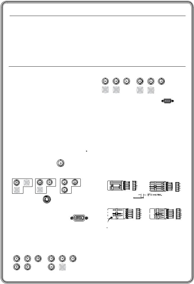
Rear panel video inputs
SDI input (DVS 304 D or AD models only) 
Attach an SDI source to this optional BNC.
Input 1: Composite video |
VID |
|
||
Input 2: Composite/S-video/YUVi/YUVp |
||||
Composite Video |
S-video (YC) |
Component Video (Y, R-Y, B-Y) |
||
-Y |
|
B-Y |
Y |
-Y |
/VID |
/VID |
/C |
/VID |
/C |
-Y |
-Y |
|
R-Y |
|
Input 3: S-video |
3 |
YC |
|
|
Input 4: Composite/S-video/YUVi/YUVp/RGBcvS/
RGB/R-Y,Y,B-Y/YC/VID
RGB scaled/RGB pass through
4
Step 4
Attach output devices to the scaler.
Rear panel video outputs
Output BNC connectors
RGBHV |
|
|
RGBS |
|
G |
R |
|
G |
B |
|
/B-Y |
|||
-Y |
-Y |
-Y |
|
|
|
|
Step 5 (for DVS 304 A or DVS 304 AD only)
Connect up to four balanced or unbalanced stereo audio input devices to the DVS 304 as shown below. Each audio input has a 3.5 mm, 5-pole captive screw connector.
For detailed wiring instructions, see chapter 2 “Installation and Operation”.
Balanced and unbalanced audio input
Unbalanced Input |
Balanced Input |
(high impedance) |
(high impedance) |
Tip |
R L |
|
|
Tip |
|
|
Sleeve |
AUDIO |
|
|
|
||
|
Tip |
R L |
AUDIO |
|||
Sleeve |
|
|||||
|
|
|
|
Ring |
|
|
Tip |
|
|
Sleeves |
|
|
|
|
|
|
|
Ring |
|
|
|
|
|
|
Do not tin the wires! |
|
|
Balanced and unbalanced audio output |
|
|||||
See Caution Tip |
|
RL |
AUDIO |
Tip |
RL |
|
|
|
Ring |
|
|||
|
|
|
|
|
|
|
Sleeve (s) |
|
|
|
Sleeve (s) |
|
|
Tip |
|
|
|
Tip |
|
|
See Caution |
|
|
|
Ring |
|
|
Unbalanced Stereo Output Balanced Stereo Output
 CAUTION
For unbalanced audio, connect the sleeve(s) to the center contact ground. DO NOT connect the sleeve(s) to the negative (-) contacts.
Step 6
Plug the DVS 304, and the input and output devices into a grounded AC source, then turn on the input and output devices.
/ |
V |
H/ |
HV |
|
HV |
DVS 304 • Quick Start QS-1

Quick Start — DVS 304, cont’d
Step 7
Use the front panel controls and LCD menu screens (shown in Appendix A) or RS-232 programming to configure the scaler.
See chapter 2, “Installation and Operation” for more detailed operating procedures, chapter 3,
“Serial Communication” for programming information, and chapter 4, “Ethernet Control” for details on the default Web pages.
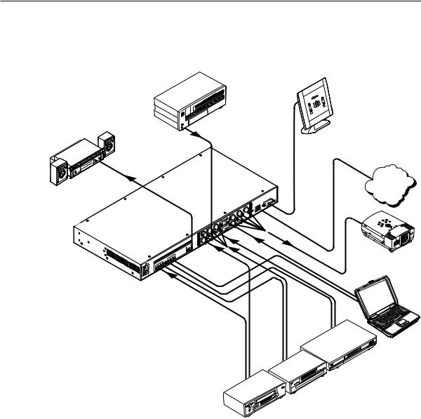
DVD Player
DVS 304 |
Laptop Computer |
|
100-240V |
.3A |
SDI |
Y |
R-Y |
RGB/R-Y,Y,B-Y/YC/VID |
R |
G |
B |
|
RS-232 |
|
|
|
|
|
|
|||||||
|
I |
|
/VID |
|
|
/R-Y |
/Y |
/B-Y |
O |
|
|
|
|
|
|
|
|
|
|
U |
|
|
|
|
N |
|
|
|
|
|
|
|
|
|
|
|
|
|
|
4 |
|
|
|
T |
|
|
|
|
P |
|
|
|
|
|
|
LAN |
|
||
|
|
|
|
|
|
|
|
P |
|
||
|
U |
|
|
|
|
|
|
|
RESET |
|
|
|
|
|
|
|
|
|
|
U |
|
||
|
T |
|
|
|
|
|
|
|
|
|
|
|
|
|
|
|
|
|
|
T |
|
|
|
|
|
|
Y |
YC |
|
H/ |
|
|
|
|
|
50/60 Hz |
1 |
2 |
RGB/R-Y,Y,B-Y |
HV |
|
|
|
|
|
||
3 |
|
|
|
|
ACT |
LINK |
RS-232 Control
VCR
LCD Projector |
Plasma Display |
Document Camera
DVS 304 Application example
Sound System |
DVD Player |
|
DVS 304A |
Laptop Computer |
100-240V |
.3A |
|
|
|
|
|
|
SDI |
Y |
R-Y |
RGB/R-Y,Y,B-Y/YC/VID |
R |
G |
B |
|
|
|
|
|
|
|
|
|
|
|
|
|
|
|||||||
|
|
|
|
|
|
|
I |
|
/VID |
|
|
/R-Y |
/Y |
/B-Y |
O |
|
|
|
|
|
|
|
|
|
|
|
|
|
|
|
|
U |
|
|
|
|
|
|
|
AUDIO |
|
|
N |
|
|
|
|
|
|
|
|
|
|
|
|
|
|
|
|
|
P |
|
|
|
4 |
|
|
|
T |
LAN |
|
|
|
|
|
|
|
|
|
|
|
|
|
|
|
P |
RS-232 |
||
|
|
INPUTS |
|
OUTPUT |
U |
|
|
|
|
|
|
|
RESET |
||||
|
L 1 R |
L 4 R |
|
|
|
|
|
|
|
U |
|
||||||
|
L 2 R |
L 3 R |
L |
R |
T |
|
|
|
|
|
|
|
|
|
|||
|
|
|
|
|
|
|
|
|
|
|
|
|
|
T |
|
|
|
50/60 Hz |
|
|
|
|
|
|
|
|
Y |
YC |
|
H/ |
|
|
|
|
|
|
|
|
|
|
|
1 |
2 |
RGB/R-Y,Y,B-Y |
HV |
|
|
|
ACT |
LINK |
|||
|
|
|
|
|
|
|
3 |
|
|
|
|
||||||
RS-232 Control
VCR
LCD Projector
DSS Receiver |
Plasma Display |
DVS 304 A Application example
QS-2 DVS 304 • Quick Start

Table of Contents
Chapter One • Introduction ...................................................................................................... |
1-1 |
About this Manual..................................................................................................................... |
1-2 |
About the DVS 304, DVS 304 A, DVS 304 D, and DVS 304 AD......................... |
1-2 |
Controlling the DVS 304 video and RGB scaler..................................................................... |
1-2 |
Features....................................................................................................................................... |
1-2 |
Options and accessories............................................................................................................ |
1-4 |
Chapter Two • Installation and Operation .................................................................... |
2-1 |
Mounting the Scaler................................................................................................................. |
2-2 |
Tabletop/desktop placement................................................................................................... |
2-2 |
UL guidelines for rack mounted devices........................................................................... |
2-2 |
Rack mounting the DVS 304 ................................................................................................... |
2-3 |
Rack mounting the DVS 304 A ................................................................................................. |
2-4 |
A pplication diagram................................................................................................................. |
2-5 |
Rear Panel Features................................................................................................................... |
2-6 |
Front Panel Features................................................................................................................. |
2-9 |
Input selection buttons............................................................................................................. |
2-9 |
Menu navigation buttons......................................................................................................... |
2-9 |
LCD menu display and controls............................................................................................... |
2-9 |
Menus, Configuration, and Adjustments.................................................................. |
2-10 |
Moving through menus by using front panel controls...................................................... |
2-10 |
Menu overview ........................................................................................................................ |
2-10 |
Start auto image...................................................................................................................... |
2-12 |
Input configuration................................................................................................................. |
2-12 |
Input 1 video type.............................................................................................................. |
2-13 |
Input 2 video type.............................................................................................................. |
2-13 |
Input 3 video type.............................................................................................................. |
2-13 |
Input 4 video type.............................................................................................................. |
2-13 |
SDI input (SDI IN) ................................................................................................................ |
2-13 |
SDI de-interlacer options................................................................................................... |
2-13 |
Picture control.......................................................................................................................... |
2-14 |
Output configuration.............................................................................................................. |
2-14 |
Resolution and refresh rates............................................................................................. |
2-15 |
Output Signal..................................................................................................................... |
2-15 |
Sync Polarity....................................................................................................................... |
2-15 |
A udio configuration (DVS 304 A and DVS 304 A D only) ................................................... |
2-16 |
Memory preset......................................................................................................................... |
2-16 |
Save memory preset........................................................................................................... |
2-16 |
Clear (CLR) memory preset................................................................................................ |
2-17 |
Recalling a preset............................................................................................................... |
2-17 |
Input preset.............................................................................................................................. |
2-17 |
IP configuration ...................................................................................................................... |
2-17 |
A dvanced configuration......................................................................................................... |
2-18 |
A uto Image......................................................................................................................... |
2-18 |
Blue mode........................................................................................................................... |
2-18 |
A uto sw itch mode.............................................................................................................. |
2-18 |
PRELIMINARY
DVS 304 • Table of Contents TOC-i

PRELIMINARY
Table of Contents, cont’d
RGB Delay........................................................................................................................... |
2-19 |
OSD label............................................................................................................................ |
2-19 |
Test pattern........................................................................................................................ |
2-19 |
Enhance mode.................................................................................................................... |
2-19 |
Refresh Lock....................................................................................................................... |
2-19 |
A uto Memory..................................................................................................................... |
2-19 |
Picture-in-picture mode.......................................................................................................... |
2-20 |
Changing the input............................................................................................................ |
2-20 |
Using the sw ap feature...................................................................................................... |
2-21 |
Exit menu.................................................................................................................................. |
2-21 |
Resetting an Input................................................................................................................... |
2-21 |
Resetting the Unit.................................................................................................................... |
2-22 |
System Reset............................................................................................................................... |
2-22 |
Front Panel Lockout (Executive mode) ....................................................................... |
2-23 |
IR 902 Infrared Remote Control....................................................................................... |
2-24 |
Setting up the DVS to work with a Matrix switcher.......................................... |
2-25 |
Using the DVS and matrix sw itcher after the DVS is |
|
synchronized to the matrix sw itcher.................................................................................... |
2-27 |
Removing the Sync to Matrix Script.................................................................................. |
2-28 |
Minimize synchronization problems w ithout using |
|
the Sync to Matrix feature................................................................................................. |
2-28 |
Chapter Three • Serial Communication ......................................................................... |
3-1 |
SIS™ Programmer’s Guide...................................................................................................... |
3-2 |
Host-to-scaler and scaler to host communications............................................................... |
3-2 |
Scaler-initiated messages..................................................................................................... |
3-2 |
Using the command/response tables...................................................................................... |
3-2 |
Copyright information......................................................................................................... |
3-3 |
Passw ord information.......................................................................................................... |
3-3 |
Error responses..................................................................................................................... |
3-4 |
References to errors (at command descriptions on the follow ing pages) ........................ |
3-4 |
Symbol definitions..................................................................................................................... |
3-5 |
Command/response table for SIS commands ....................................................................... |
3-8 |
Command/response table for IP control port commands.................................................. |
3-15 |
Control Software for Windows®...................................................................................... |
3-23 |
Dow nloading the softw are .................................................................................................. |
3-23 |
Installing the softw are from a CD......................................................................................... |
3-23 |
Using the control program..................................................................................................... |
3-23 |
Using the help program.......................................................................................................... |
3-25 |
TOC-ii DVS 304 • Table of Contents

Chapter Four • Ethernet Control ......................................................................................... |
4-1 |
Accessing and Using the Web Server............................................................................. |
4-2 |
Navigating the Default Web Pages................................................................................. |
4-3 |
Status .......................................................................................................................................... |
4-3 |
System Status page.............................................................................................................. |
4-3 |
Configuration............................................................................................................................. |
4-4 |
System Settings page........................................................................................................... |
4-4 |
IP settings fields.............................................................................................................. |
4-4 |
Scaler Settings page............................................................................................................. |
4-6 |
Passw ords.............................................................................................................................. |
4-7 |
Firmw are upgrade page...................................................................................................... |
4-8 |
File Management ...................................................................................................................... |
4-9 |
Control...................................................................................................................................... |
4-10 |
User Control page.............................................................................................................. |
4-10 |
Video/A udio breakaw ay (DVS 304 A or DVS 304 A D only) ........................................ |
4-10 |
Presets page........................................................................................................................ |
4-11 |
Memory presets............................................................................................................ |
4-11 |
Input presets (input 4 only) ......................................................................................... |
4-11 |
PIP Setup page.................................................................................................................... |
4-12 |
A udio (DVS 304 A only) ................................................................................................ |
4-12 |
Appendix A • Menu System...................................................................................................... |
A -1 |
DVS 304 Menu System............................................................................................................ |
A -2 |
Default cycle menu .................................................................................................................. |
A -2 |
Main menu ............................................................................................................................... |
A -2 |
Start A uto Image menu .......................................................................................................... |
A -3 |
Input Configuration menu ..................................................................................................... |
A -3 |
Picture Control menu .............................................................................................................. |
A -3 |
Output Configuration menu .................................................................................................. |
A -4 |
A udio Configuration menu .................................................................................................... |
A -4 |
Memory Preset menu .............................................................................................................. |
A -4 |
IP Configuration menu ........................................................................................................... |
A -5 |
A dvanced Configuration menu ............................................................................................. |
A -5 |
Exit menu .................................................................................................................................. |
A -5 |
Executive Mode menu ............................................................................................................ |
A -6 |
Appendix B • Reference Material.......................................................................................... |
B-1 |
Specifications................................................................................................................................ |
B-2 |
Part Numbers and Accessories........................................................................................... |
B-5 |
Included parts............................................................................................................................. |
B-5 |
A ccessories.................................................................................................................................. |
B-5 |
Serial Digital Interface (SDI) Card Installation......................................................... |
B-6 |
All trademarks mentioned in this manual are the properties of their respective owners.
68-1039-01
Rev. B
11 08
DVS 304 • Table of Contents TOC-iii
PRELIMINARY

Table of Contents, cont’d
PRELIMINARY
TOC-iv DVS 304 • Table of Contents

DVS 304 Chapter1One
Introduction
A bout this Manual
A bout the DVS 304, DVS 304 D, DVS 304 A , DVS 304 A D

Introduction
About this Manual
This manual discusses how to install, configure, and operate the Extron DVS 304 video and RGB scaler and how to operate the optional IR 902 infrared remote control (part #70-495-01).
Throughout this manual the terms “DVS”, “digital video scaler”, and “scaler” are used interchangeably to refer to the same product. All instances refer to all models in the series unless noted otherwise.
About the DVS 304, DVS 304 A, DVS 304 D, and DVS 304 AD
The DVS 304 series (DVS 304, DVS 304 A, DVS 304 D, and DVS 304 AD ) are 4-input, 1-output high performance RGB and video scalers offering 62 output rates, including HDTV. These products provide scaling solutions for boardrooms, conference rooms, and home theaters, as well as rental and staging applications.
The two DVS 304 scalers come in a half rack model (DVS 304) with an SDI option, and a full rack model (DVS 304 A) with an SDI option and balanced/unbalanced audio.
All versions of the DVS 304 can be controlled remotely using Extron’s Simple Instruction Set (SIS™) commands via RS-232, or through an Ethernet LAN connection using embedded Web pages.
The DVS 304 scales from composite video, S-video, component (Y, R-Y, B-Y) video, and RGB video to computer-video (RGBHV/RGBS/RGsB) or HD component.
It can also output to two separate display devices via individually buffered BNC and 15-pin HD connectors.
Controlling the DVS 304 video and RGB scaler
The DVS 304 can be controlled using one or more of the following methods:
•The front panel controls.
•A computer, a touch screen panel, or any other device that can send and receive the serial communications through the RS-232 port. The Extron Simple Instruction Set (SIS) is a set of simple keystroke commands that can be used with any such devices, and Extron’s control software for Windows® provides a graphical interface for controlling the scaler from a computer.
•The optional IR 902 remote control, replicating most of the front panel controls.
•Ethernet control via IP Link, enabling the DVS 304 to be controlled and pro-actively monitored over a LAN, WAN, or the Internet.
Features
Four inputs:
SDI video input (optional) — One BNC connector on the rear panel accepts SDI video. During setup, the SDI input is assigned to input 1, 2, 3, or 4 (the default is none).
Input 1 — One BNC connector on the rear panel accepts composite video.
Input 2 — Three BNC connectors on the rear panel accept composite video, S-video, or component video.
Input 3 — A 4-pin mini-DIN connector accepts an S-video signal. Input 4 — A 15-pin HD connector accepts an RGB, component video,
1-2 DVS 304 • Introduction
S-video or composite video signal.
RGB and video scaling — Provides a high performance scaling engine with the capacity to scale standard definition video, high definition video, and computer-video signals up or down in resolution.
Picture Control — Allows size, position, brightness, contrast, color, tint, detail, zoom and pan adjustments for each input.
Picture-In-Picture — Allows for a low resolution (YUVi, S-video, and composite video) input or a high resolution (VGA and YUVp) input for the primary or secondary picture.
Memory and input presets — Memory presets save sizing, positioning, and picture control settings.
Input presets (on input 4 only) save input configuration, picture control, and OSD (on-screen display) text.
Auto image™ — Auto image automatically sizes, centers, and optimizes the image to that of the scaled output rate, filling the window with the image.
IP Link® — IP Link-enabled products offer an integrated Web server with high performance architecture, global compatibility with industry standard Ethernet communication protocols, multi-user support, and a Web-based asset management application specifically designed to work with products that include IP Link technology.
Buffered video outputs — Five rear-panel BNC connectors and one VGA-type 15-pin HD connector provide connections for RGB or Y, R-Y, B-Y output. Both outputs (the BNCs and 15-pin HD connector) are active at all times for simultaneous output.
Device control — The scaler has four methods of control; by the scaler’s front panel, via a computer or other RS-232 control device, using the optional IR 902 remote control, or via Signal Enhancements Windows Control Program.
Scaled outputs — The DVS 304 offers 62 different output rates.
RS-232 configuration — The DVS 304 can be configured by using the Extron control software for Windows or by using a third party control system.
Front panel security lockout (executive mode) — To prevent accidental changes to the unit’s settings, the DVS 304 provides front panel lockout of all controls except input switching.
3:2 pull down detection for NTSC and 2:2 film detection for PAL video sources
— These patented, advanced film mode processing features, help maximize image detail and sharpness for video sources that originated from film. When film is converted to NTSC video, the film frame rate has to be matched to the video frame rate in a process called 3:2 pull down. “Jaggies” and other image artifacts can result if conventional de-interlacing techniques are used on
film-source video. The DVS 304’s advanced film mode processing recognizes signals that originated from film. The DVS 304 then applies video processing algorithms that optimize the conversion of video that was made with the
3:2 pull down process. This results in richly detailed images with sharply defined lines. A similar process is used for PAL film-source video.
Versatile mounting options — The DVS 304 and DVS 304 D are 1U high, half rack wide rack mountable devices. Alternatively, they can be placed on a table or other furniture. Rubber feet and rack mounting hardware are included.
The 1U high and full rack DVS 304 A and DVS 304 AD (audio models) can be rack mounted using included rack/through-desk mounting brackets.
DVS 304 • Introduction |
1-3 |

Introduction, cont’d
Options and accessories
The DVS 304’s optional equipment includes:
•IR 902 remote control — Extron’s IR 902 (part #70-495-01) is an infrared remote control which replicates most of the front panel controls of the DVS 304 (except the Menu and Next buttons).
•SDI input card — Serial digital interface (SDI) input can be added to the DVS 304 model by the installation of an SDI input card (part #70-168-01).
1-4 DVS 304 • Introduction

DVS 304 Chapter2Two
Installation and Operation
Mounting the Scaler
Rear Panel Features
Front Panel Features
Menus, Configuration, and A djustments
Resetting an Input
Resetting the Unit
System Reset
Front Panel Lockout (Executive Mode)
IR 902 Infrared Remote Control
Setting up the DVS to w ork w ith a Matrix Sw itcher

Installation and Operation
Mounting the Scaler
The DVS 304 is 1U high, half rack wide, and is rack mountable. Alternatively, it can be placed on a table or other furniture. Rubber feet and rack mounting hardware are included.
The 1U high and full rack DVS 304 A (audio model) can be rack mounted using included rack/through-desk mounting brackets.
Tabletop/desktop placement
Four self-adhesive rubber feet are included with the DVS 304. For tabletop use, attach one foot to each corner of the bottom side of the unit and place the unit in the desired location.
UL guidelines for rack mounted devices
The following Underwriters Laboratories (UL) guidelines pertain to the safe installation of the DVS in a rack.
1. Elevated operating ambient temperature — If installed in a closed or multi-unit rack assembly, the operating ambient temperature of the rack environment may be greater than room ambient temperature. Therefore, install the DVS 304 in an environment compatible with the maximum ambient temperature
(Tma = +122 °F, +50 °C) specified by Extron.
2. Reduced air flow — Install the equipment in a rack so that the amount of air flow required for safe operation of the equipment is not compromised.
3. Mechanical loading — Mount the equipment in the rack so that a hazardous condition is not achieved due to uneven mechanical loading.
4. Circuit overloading — Connect the equipment to the supply circuit and consider the effect that circuit overloading might have on overcurrent protection and supply wiring. Appropriate consideration of equipment nameplate ratings should be used when addressing this concern.
5. Reliable earthing (grounding) — Maintain reliable grounding of rackmounted equipment. Pay particular attention to supply connections other than direct connections to the branch circuit (e.g. use of power strips).
2-2 DVS 304 • Installation and Operation
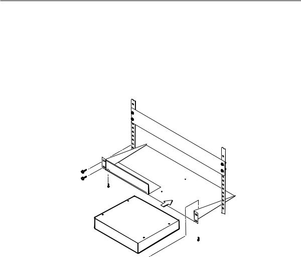
Rack mounting the DVS 304
1. |
If feet were installed on the bottom of the DVS 304, remove them. |
2. |
Place the DVS 304 on one half of the 1U (one unit high, one unit wide) rack |
|
shelf (part #60-190-01). Align the front of the DVS 304 with the front of the |
|
shelf, and align the threaded holes on the bottom of the DVS 304 with the |
|
holes in the rack shelf. |
3. |
Attach the DVS 304 to the rack shelf with the two provided 4-40 x 1/16" |
|
machine screws. Insert the screws from the underside of the shelf, and |
|
securely fasten them into diagonally-opposite corners (figure 2-1). |
False front panel uses 2 front holes.
|
|
|
(2) 4-40 x 3/16" Screws |
|
|
|
|
|
|
mounting holes on |
|
|
|
||
|
|
opposite corners. |
|
Figure 2-1 — Rack mounting a half rack device |
|||
4. |
Attach the false front panel (provided with the universal rack shelf) to the |
||
|
unoccupied side of the rack (as shown above), or install a second half-rack- |
||
|
width device in that side by repeating steps 1 – 3. |
||
5. |
Attach the rack shelf to the rack using four 10-32 x 3/4" bolts (provided). |
||
|
Insert the bolts through #10 beveled washers, then through the holes in the |
||
|
rack ears and rack (figure 2-1). |
||
DVS 304 • Installation and Operation |
2-3 |
Installation and Operation, cont’d
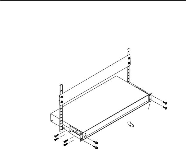
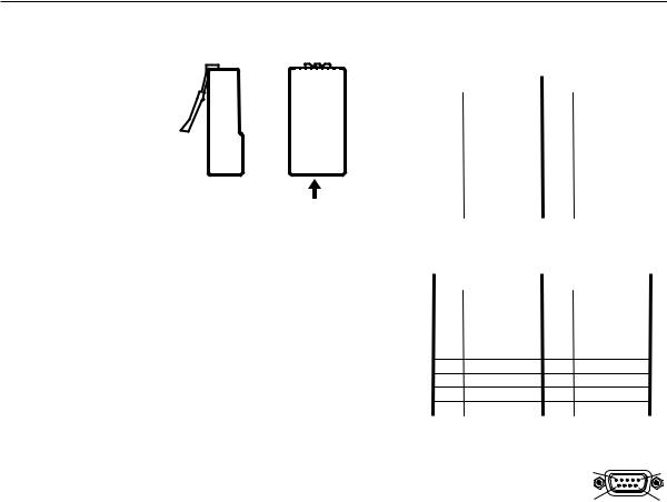
Rack mounting the DVS 304 A
To mount the DVS 304 A in a rack, do the following:
1. If feet were installed on the bottom of the DVS 304, remove them.
2.Attach the included rack/through-desk mounting brackets
(part #70-077-03) to the unit using eight machine screws supplied with the mounting kit.
Rack Mount
Bracket
Figure 2-2 — Attach the mounting brackets and install in rack
3.Insert the unit into the rack and align the holes in the mounting brackets with the holes in the rack. Use four machine screws to attach the brackets to the rack.
2-4 DVS 304 • Installation and Operation
Application diagram
The diagram shown below is an example of a typical DVS 304 AD application with cable connections.
Tape Deck
Output
D
Digital Video Scaler w/ Audio
RS-23 |
2 |
|
B |
O |
/B-Y |
U |
G |
T |
/Y |
P |
|
U |
R |
T |
/R-Y |
|
,B-Y/YC/ |
VID |
|
|
/R-Y,Y |
V |
RGB |
|
R-Y |
H/ |
/C |
HV |
|
|
|
Y |
4 |
|
|
|
|
/VID |
|
,B-Y |
|
|
I |
|
|
|
|
SD |
|
|
RGB |
/R-Y,Y |
|
|
|
|
YC |
|
II |
|
|
B-Y |
3 |
|
N |
|
|
|
||
P |
VID |
|
2 |
|
|
U |
|
|
|
||
T |
|
|
|
|
|
1
AUD |
IO |
Audio

232 Control
TCP/IP
Network
Projector (RGB)
(RGB)
Receiver (S-video)
(Component)
(Video)
Figure 2-3 — Application diagram example of the DVS 304 AD
DVS 304 • Installation and Operation |
2-5 |
Installation and Operation, cont’d
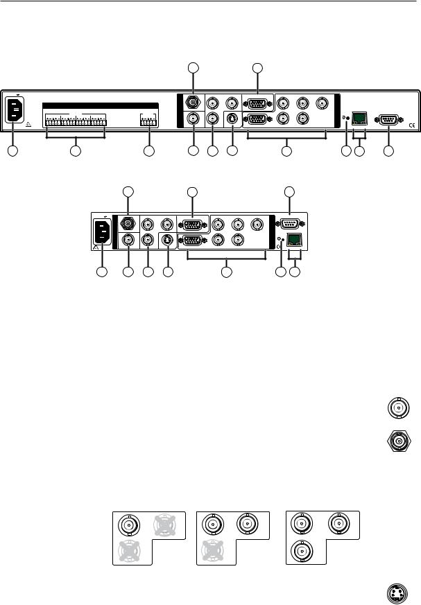
Rear Panel Features
The rear panels of the DVS 304 D and DVS 304 AD models (figures 2-4 and 2-5) contain all of the possible connectors available on the DVS 304 series of scalers.
|
|
|
|
|
|
|
|
4a |
|
|
|
7 |
|
|
|
|
|
|
|
|
100-240V .3A |
|
|
|
|
|
|
|
SDI |
Y |
B-Y |
RGB/R-Y,Y,B-Y/YC/VID |
|
|
R |
G |
B |
|
|
|
|
|
|
|
|
|
|
|
|
|
|
|
|
|
||||||||
|
|
|
|
|
|
|
I |
|
/VID |
|
|
|
|
|
/R-Y |
/Y |
/B-Y O |
|
|
|
|
|
|
|
|
|
|
|
|
|
|
|
|
|
|
|
U |
|
|
|
|
|
AUDIO |
|
|
|
|
|
N |
|
|
|
|
|
|
|
|
|
|
|
|
|
|
|
|
|
|
|
|
|
4 |
|
|
|
|
|
|
T |
|
|
|
||
|
|
|
|
|
|
|
P |
|
|
|
|
|
|
|
|
|
LAN |
|
||
|
INPUTS |
|
|
OUTPUT |
|
|
|
|
|
|
|
|
|
|
P |
|
RS-232 |
|||
|
|
|
|
U |
|
|
|
|
|
|
|
|
|
RESET |
|
|||||
L 1 R |
L 2 R L 3 R L 4 R |
|
|
L |
R |
|
|
|
|
|
|
|
|
|
|
U |
|
|
||
|
|
|
T |
|
|
|
|
|
|
|
|
|
|
|
|
|||||
|
|
|
|
|
|
|
|
|
|
|
|
|
|
|
|
T |
|
|
|
|
50/60 Hz |
|
|
|
|
|
|
|
D 2 |
Y 3 |
YC |
|
|
|
|
H/ |
|
|
|
|
|
|
|
|
|
|
|
1 |
|
RGB/R-Y,Y,B-Y |
|
|
HV |
|
|
|
ACT LINK |
|
||||
1 |
2 |
|
|
|
3 |
|
|
4 |
5 |
6 |
|
|
|
|
8 |
|
|
9 |
10 |
11 |
|
Figure 2-4 — DVS 304 AD rear panel connectors |
|
|
|
|
|||||||||||||||
|
|
|
4a |
|
|
|
|
7 |
|
|
|
|
|
|
11 |
|
|
|
|
|
|
100-240V |
.3A |
SDI |
|
Y |
B-Y |
RGB/R-Y,Y,B-Y/YC/VID |
R |
|
G |
B |
|
|
RS-232 |
|
|
|
|
|
|
|
|
|
|
|
|
|
|
|
|
|
|
|
||||||||
|
|
I |
|
|
/VID |
|
|
|
/R-Y |
|
/Y |
/B-Y |
O |
|
|
|
|
|
|
|
|
|
|
|
|
|
|
|
|
|
|
|
U |
|
|
|
|
|
|
|
|
|
|
N |
|
|
|
|
|
|
|
|
|
|
|
|
|
|
|
|
|
|
|
|
|
|
|
|
4 |
|
|
|
|
|
T |
|
|
|
|
|
|
|
|
|
|
P |
|
|
|
|
|
|
|
|
|
|
LAN |
|
|
|
|
|
||
|
|
|
|
|
|
|
|
|
|
|
|
P |
|
|
|
|
|
|
||
|
|
U |
|
|
|
|
|
|
|
|
|
|
RESET |
|
|
|
|
|
||
|
|
|
|
|
|
|
|
|
|
|
|
U |
|
|
|
|
|
|||
|
|
T |
|
|
|
|
|
|
|
|
|
|
|
|
|
|
|
|
|
|
|
|
|
|
|
|
|
|
|
|
|
|
T |
|
|
|
|
|
|
|
|
|
|
|
D |
|
Y 3 |
YC |
|
|
H/ |
|
|
|
|
|
|
|
|
|
|
|
|
50/60 Hz |
1 |
2 |
RGB/R-Y,Y,B-Y |
HV |
|
|
|
|
|
ACT |
LINK |
|
|
|
|
||||
|
1 |
|
4 |
|
5 |
6 |
|
|
8 |
|
|
|
|
9 |
10 |
|
|
|
|
|
Figure 2-5 — DVS 304 D rear panel power connector
A AC power connector — Plug a standard IEC power cord into this connector to connect the scaler to a 100 to 240 V AC, 50 Hz or 60 Hz power source. The front panel control and input selection buttons light in sequence during power-up.
B C D
Audio input — Plug up to four, 3.5 mm, female, five-pole, captive screw connectors for balanced/unbalanced variable audio input.
Audio output — Plug one, 3.5 mm, female, five-pole captive screw connector for balanced/unbalanced variable audio output.
Video input 1: Composite video — Connect a composite video |
|
signal to this female, BNC connector. |
VID |
|
Ü |
Optional SDI (serial digital interface) input connector — Connect |
||||
|
an SDI signal to this female BNC connector. During setup, the SDI |
||||
|
input can be assigned to one of the other unused inputs. |
|
|||
E |
Video input 2: Composite/S-video/Component — Connect composite video, |
||||
|
S-video, and component video signals. Connect cables for the appropriate |
||||
|
signal type, as shown here. |
|
|
|
|
|
Composite Video |
S-video (YC) |
|
Component Video (Y, R-Y, B-Y) |
|
|
-Y |
Y |
B-Y |
Y |
-Y |
|
/VID |
/VID |
/C |
/VID |
/C |
|
R-Y |
-Y |
|
R-Y |
|
F |
Video input 3: S-video — Connect an S-video signal to this |
|
4-pin, mini-DIN female connector. |
3 YC
2-6 DVS 304 • Installation and Operation
G |
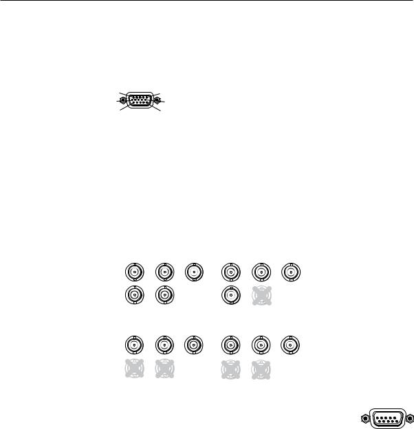
Video input 4: RGB/R-Y, Y, B-Y/YC/VID — Connect RGBHV, RGBS, RGsB, |
|
RGBcvS, YUVi, YUVp, S-video and composite video through this 15-pin HD |
|
connector. See pin configurations below. |
5 |
RGB/R-Y,Y,B-Y/YC/VID |
1 |
|
||
10 |
|
6 |
15 |
4 |
11 |
|
Signal |
Input 4 Pin Configuraton |
||||
|
|
|
|
|
|
|
Pin 1 |
Pin 2 |
Pin 3 |
Pin 13 |
Pin 14 |
RGBHV |
R |
G |
B |
H |
V |
RGBS |
R |
G |
B |
S |
|
RGsB |
R |
G |
B |
|
|
YUV |
R-Y |
Y |
B-Y |
|
|
S-video |
|
Y |
C |
|
|
Video |
|
Vid |
|
|
|
NEquipment following the SCART interconnection standard may be connected to the RGBcvS input cabling configuration.
H |
RGB (RGBHV, RGBS, RGsB) or HD component (R-Y, Y, B-Y) video BNC |
|
outputs — Connect coaxial cables from a display device to these BNCs for a |
|
scaled or pass-through RGB or a scaled component video output. The output |
|
can be scaled to 62 different output rates (see table on page 2-15). |
|
RGBHV |
|
|
RGBS |
|
|
R |
G |
B |
R |
G |
B |
|
/B-Y |
||||||
-Y |
|
-Y |
-Y |
|
||
|
|
|
||||
/ |
V |
|
H/ |
|
|
|
HV |
|
|
HV |
|
|
|
|
RGsB |
Component Video (Y, R-Y, B-Y) |
||||
R |
G |
|
R |
G |
|
|
-Y |
|
-Y |
R-Y |
Y |
B-Y |
|
V
HV
RGB or HD component (R-Y, Y, B-Y) 15-pin HD video output —
Connect an RGB video display or HD component video display RGB/R-Y,Y,B-Y/YC/VID to this HD 15-pin connector. 


N Both Houtputs are buffered and can be connected |
4 |
|
|
simultaneously to two different displays. The sync and video formats will |
|
be the same for both outputs. |
|
I Reset button and LED — A recessed button that allows for manual resets |
|
using an Extron Tweeker, pointed stylus or ballpoint pen. The unit can be reset to four modes (see “Resetting the Unit” later in this chapter for additional information).
|
The green LED flashes to show the reset mode indicators and that power is |
|
on. |
J |
LAN connector — Plug an RJ-45 jack into this socket to connect the unit to a |
|
computer network. Use a patch cable to connect to a switch, hub, or router. |
|
See the following page for wiring information. |
|
LAN Activity LED — A blinking yellow LED indicates LAN activity. |
|
Link LED — The green LED lights to indicate a good LAN connection. |
DVS 304 • Installation and Operation |
2-7 |
Installation and Operation, cont’d
|
|
Pins: |
|
Straight-through Cable |
|||||
12345678 |
|
|
|
||||||
|
|
|
|
|
(for connection to a switch, hub, or router) |
||||
|
|
|
|
|
|
|
|
|
|
|
|
|
|
|
|
End 1 |
|
End 2 |
|
|
|
|
|
|
Pin |
Wire Color |
Pin |
Wire Color |
|
|
|
|
|
|
|||||
|
|
|
|
|
1 |
white-orange |
1 |
white-orange |
|
|
|
|
|
|
2 |
orange |
2 |
orange |
|
|
|
|
|
|
|||||
|
|
|
|
|
|
|
|
|
|
|
|
|
|
|
3 |
white-green |
3 |
white-green |
|
|
|
|
|
|
4 |
blue |
4 |
blue |
|
|
|
|
|
|
5 |
white-blue |
5 |
white-blue |
|
Side View |
6 |
green |
6 |
green |
|||||
7 |
white-brown |
7 |
white-brown |
||||||
|
|
Insert |
|||||||
|
|
8 |
brown |
8 |
brown |
||||
|
|
Twisted |
|||||||
|
|
|
|
|
|
||||
Pair Wires |
|
|
|
|
|||||
RJ-45 Connector |
|
Crossover Cable |
|||||||
|
|
|
|
|
|
(for direct connection to a PC) |
|||
|
|
|
|
|
|
|
|
|
|
|
|
|
|
|
|
End 1 |
|
End 2 |
|
|
|
|
|
|
Pin |
Wire Color |
Pin |
Wire Color |
|
|
|
|
|
|
1 |
white-orange |
1 |
white-green |
|
|
|
|
|
|
2 |
orange |
2 |
green |
|
|
|
|
|
|
3 |
white-green |
3 |
white-orange |
|
|
|
|
|
|
4 |
blue |
4 |
blue |
|
|
|
|
|
|
5 |
white-blue |
5 |
white-blue |
|
|
|
|
|
|
6 |
green |
6 |
orange |
|
|
|
|
|
|
7 |
white-brown |
7 |
white-brown |
|
|
|
|
|
|
8 |
brown |
8 |
brown |
|
Figure 2-6 — Wiring the RJ-45
K |
Remote (RS-232/contact closure) 9-pin port — This connector |
|
provides for two-way RS-232 communication. See chapter 3, |
|
“Serial Communication”, for information on how to install and |
|
use the control software and SIS commands. |
5 |
RS-232 |
1 |
|
9 |
6 |
The default protocol is 9600 baud, 1 stop bit, no parity, and no flow control.
The rear panel RS-232 9-pin D female connector has the following pin assignments:
Pin |
RS-232 function |
Description |
1 |
Input #1 |
Contact closure |
2 |
Tx |
Transmit data |
3 |
Rx |
Receive data |
|
|
|
4 |
Input #2 |
Contact closure |
5 |
Gnd |
Signal ground |
|
|
|
6 |
Input #3 |
Contact closure |
7 |
Input #4 |
Contact closure |
8 |
– |
No connection |
9 |
– |
Reserved |
The Remote connector also provides a way to select an input using a remote contact closure device. Contact closure control uses pins on the RS-232 connector that are not used by the RS-232 interface (see preceding table).
To select a different input number using a contact closure device, short the pin for the desired input number to logic ground (pin 5).
2-8 DVS 304 • Installation and Operation
Front Panel Features
The front panel buttons, controls, LCD, and infrared sensor are found on all models of the DVS 304 scaler series. The LEDs beside each input button will light green when the button is pressed.
DVS 304
DIGITAL VIDEO SCALER
|
|
|
|
|
ADJUST |
1 |
2 |
3 |
4 |
MENU |
NEXT |
|
|
|
|
|
IR |
1 2 3 4 5 6 7
Figure 2-7 — DVS 304 and DVS 304 A front panel
Input selection buttons
A |
Input LEDs — The LED of the selected input lights when pressed. A blinking |
|
LED indicates an audio breakaway input (audio models only). |
|
Composite input button — Input 1 selects composite video input. |
|
Composite/YC/component input button — Input 2 selects composite video, |
|
YC, or component video input. |
|
S-video input button — Input 3 selects the S-video input. |
|
Universal input button — Input 4 selects the RGB scaled (RGBHV, RGBS, |
|
RGsB), RGB pass-through, YUVi, YUVp, S-video and composite video. |
Menu navigation buttons
B |
Menu button — Use this button to enter and move through the main menu |
|
system in the DVS 304. See the “Menus, Configuration, and Adjustments” |
|
section in this chapter for details. |
C |
Next button — Use this button to step through the submenus in the |
|
DVS 304 menu system. See the “Menus, Configuration, and Adjustments” |
|
section in this chapter for details. |
LCD menu display and controls
D E
LCD — Displays configuration menus and status information. See the “Menus, Configuration, and Adjustments” section in this chapter for details.
Infrared sensor — This sensor is used to receive infrared (IR) signals from the IR 902 remote control. See the “IR 902 Infrared Remote Control” section in this chapter for details.
F |
Adjust horizontal ([) knob — In the menu system, rotate this knob to scroll |
|
through menu options and make adjustments. |
G |
Adjust vertical ({) knob — In the menu system, rotate this knob to scroll |
|
through menu options and make adjustments. |
2-9

Installation and Operation, cont’d
Menus, Configuration, and Adjustments
Scaler configuration and adjustments can be performed by using the embedded Web pages and the Windows-based control program (see chapter 3, “Serial Communication” for details) or by using the front panel controls and the menus that are displayed on the DVS 304’s LCD screen. These menus are used primarily when the scaler is first set up.
Moving through menus by using front panel controls
Menu button — Press the Menu button to activate menus and scroll through the eight main menus.
Next button — Press the Next button to move between the submenus of a selected main menu. Pressing the Next button during input configuration causes the current input’s number and format type to be displayed on the LCD
Adjust ([,{) knobs — In configuration mode, rotate the Adjust horizontal ([) knob and Adjust vertical ({) knob to scroll through submenu options and to make adjustment selections. Refer to the flowcharts in this chapter and to specific sections for explanations on knob adjustments.
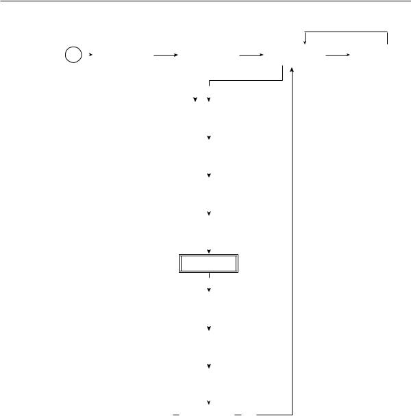
Menu overview
Power
on
The default menus appear on the LCD when no adjustments are actively being made. They cycle between the screen showing the model of the scaler (DVS 304 or DVS 304 A) and the screen that shows the active input’s number and video format, as shown below.
|
|
|
|
|
Default Cycle |
|
|
|
|
|
|
|
|
|
2 sec. |
|
|
|
|
|
|
|
|
EXTRON |
|
60-736-01 |
|
INPUT 1 |
|
|
OUTPUT |
DVS 304 |
2 sec. |
FW ver. 1.xx |
2 sec. |
COMPOSITE |
2 sec. |
|
1024 x 768@60 |
|
|
|
|
|
|
|
|
Figure 2-8 — Default menus
NFrom any menu or submenu, after 20 seconds of inactivity the DVS 304 will save all adjustment settings and time-out to the default menus.
The main menus are shown on the following pages. Use the Menu button to scroll between them.
NIf no signal is present on the currently selected input, NO SIGNAL appears in place of a signal value, e.g. INPUT 4 NO SIGNAL.
2-10 DVS 304 • Installation and Operation
|
|
|
|
|
|
|
|
|
|
|
Power |
|
|
EXTRON |
|
|
|
60-736-01 |
|
||
on |
|
|
DVS 304 |
|
|
2 sec. |
FW version 1.00 |
|
||
|
|
|
|
|
|
|
|
|
|
|
|
|
|
|
|
|
|
|
MENU |
|
|
|
|
|
|
|
|
|
|
|
|
|
|
|
|
|
|
|
|
|
|
|
|
|
|
|
|
|
|
|
START AUTO |
|
||
|
|
|
|
|
|
|
IMAGE ON IN1 |
|
||
|
|
|
|
|
|
|
|
|
|
|
|
|
|
|
|
|
|
|
|
|
|
|
|
|
|
|
|
|
|
MENU |
|
|
|
|
|
|
|
|
|
|
|
|
|
|
|
|
|
|
|
|
|
|
|
|
|
|
|
|
|
|
|
|
|
|
|
|
|
|
|
|
|
|
|
INPUT |
|
|
|
|
|
|
|
|
|
|
CONFIG |
|
|
|
|
|
|
|
|
|
|
|
|
|
|
|
|
|
|
|
|
|
|
|
|
|
|
|
|
|
|
|
|
MENU |
|
|
|
|
|
|
|
|
|
|
|
|
|
|
|
|
|
|
|
|
|
|
|
|
|
|
|
|
|
|
|
|
PICTURE |
|
|
|
|
|
|
|
|
|
|
CONTROL |
|
|
|
|
|
|
|
|
|
|
|
|
|
|
|
|
|
|
|
|
|
|
|
|
|
|
|
|
|
|
|
|
MENU |
|
|
|
|
|
|
|
|
|
|
|
|
|
|
|
|
|
|
|
|
|
|
|
|
|
|
|
|
|
|
|
|
OUTPUT |
|
|
|
|
|
|
|
|
|
|
CONFIG |
|
|
|
|
|
|
|
|
|
|
|
|
|
|
|
|
|
|
|
|
|
|
|
|
|
|
|
|
|
|
|
|
MENU |
|
|
|
|
|
|
|
|
|
|
|
|
|
|
|
|
|
|
|
|
|
AUDIO |
|
|
|
|
|
|
|
|
|
|
CONFIG |
|
|
|
|
|
|
|
|
|
|
MENU |
|
|
|
|
|
|
|
|
|
|
|
|
|
|
|
|
|
|
|
|
|
|
|
|
|
|
|
|
|
|
|
|
MEMORY |
|
|
|
|
|
|
|
|
|
|
PRESETS |
|
|
|
|
|
|
|
|
|
|
|
|
|
|
|
|
|
|
|
|
|
|
|
|
|
|
|
|
|
|
|
|
MENU |
|
|
|
|
|
|
|
|
|
|
|
|
|
|
|
|
|
|
|
|
|
|
|
|
|
|
|
|
|
|
|
|
IP |
|
|
|
|
|
|
|
|
|
|
CONFIG |
|
|
|
|
|
|
|
|
|
|
|
|
|
|
|
|
|
|
|
|
|
|
|
|
|
|
|
|
|
|
|
|
MENU |
|
|
|
|
|
|
|
|
|
|
|
|
|
|
|
|
|
|
|
|
|
|
|
|
|
|
|
|
|
|
|
ADVANCED |
|
||
|
|
|
|
|
|
|
|
CONFIG |
|
|
|
|
|
|
|
|
|
|
|
|
|
|
|
|
|
|
|
|
|
|
|
|
|
|
|
|
|
|
|
|
MENU |
|
|
|
|
|
|
|
|
|
|
|
|
|
|
|
|
|
|
|
|
|
|
||
|
|
|
|
|
|
MENU |
TO EXIT MENU |
|
||
|
|
|
|
|
|
PRESS NEXT |
|
|||
|
|
|
|
|
|
|
|
|||
|
|
|
|
|
|
|
|
|
|
|
|
|
Default Cycle |
|
|
|
|
|
|
2 sec. |
|
|
|
|
|
|
INPUT 1 |
|
|
OUTPUT |
2 sec. |
COMPOSITE |
2 sec. |
|
1024 x 768@60 |
|
|
|
|
|
|
|
|
|
|
(Audio models only)
NEXT
Figure 2-9 — Main menus
NTo return to the default screens, allow the DVS 304 to time-out (after 20 seconds). Alternatively, press the Menu button repeatedly until the Exit menu appears, then press the Next button.
NSubmenus are accessed from a main menu by pressing the Next button.
When in a submenu, press the Menu button to go out of the submenu and back to the active main menu.
DVS 304 • Installation and Operation 2-11
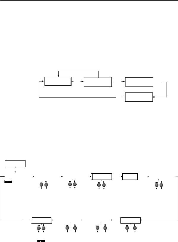
Installation and Operation, cont’d
Start auto image
Auto imaging allows you to “auto size” and “auto center” the selected image to fill the screen. The processor measures the sync frequencies of an incoming video source and uses an internal table to set the active image area, total image area, and the sampling frequency.
If an unknown input is connected to the DVS 304, the processor measures and estimates the resolution of the incoming video.
To turn on this feature, select the Advanced Config menu and choose “On”.
Start auto imaging on a selected input by pressing “Next” after the Start Auto Image menu.
Default Cycle
2 sec.
INPUT 1 |
2 sec. |
OUTPUT |
MENU |
|
COMPOSITE |
1024 x 768@60 |
|||
|
|
|||
|
|
|
NEXT |
START AUTO |
|
NEXT |
IMAGE ON IN1 |
|
|
|
|
|
|
|
|
PRESS NEXT
TO START
Figure 2-10 — Start auto image menu
NAn input with a vertical refresh rate less than 40 Hz will have to be manually centered and sized, using H/V Start and H/V Active under the Input Config menu. When a rate with a low vertical refresh rate (e.g. 720p 29.9 Hz) is applied and an Auto Image command is issued, the DVS 304 will refer to default values instead of performing a true Auto Image.
Input configuration
The following flowchart provides an overview of the Input Configuration submenus and the options for each setting.
START AUTO
IMAGE ON IN1
MENU
INPUT |
|
NEXT |
|
|
INPUT 2 |
|
CONFIG |
|
|
|
YUVi |
|
|
|
|
|
|
|
||
|
|
|
|
|
|
|
 Input 1 can only accept composite video. Input 3 can only accept S-video. Only Inputs 2 and 4 can be configured for different video types, although an SDI input can be assigned to any input.
 NEXT
NEXT
Select video format
•Composite
•S-video
•YUVi
•YUVp
•YUV Auto
Displays only when applicable
FILM MODE <OFF> ON
|
|
|
|
|
|
|
Displays only when applicable |
|
|
Displays only when applicable |
|
|
|
|
|
|
||
|
|
|
|
|
|
|
SDI INPUT |
|
|
|
SDI DE-INTER |
|
|
|
|
|
|
|
NEXT |
|
|
INPUT 4 |
|
NEXT |
|
|
NEXT |
|
NEXT |
|
|
ASPECT RATIO |
|
NEXT |
|||
|
|
RGB SCALED |
|
<*> 1 2 3 4 |
|
|
FIELD STNDRD |
|
|
4x3 |
|
|||||||
|
|
|
|
|
|
|
|
|
|
|
|
|
||||||
|
|
Select video format |
|
|
|
Assign SDI to Input # |
|
|
|
|
|
||||||
|
|
• |
Composite |
|
|
|
• |
1, 2, 3, 4, * (none) |
|
|
|
|
|
||||
|
|
• |
S-video |
|
|
|
N The SDI input signal can be |
NSDI De-interlacing options: |
|||||||||
|
|
• |
RGBcvS |
|
|
|
assigned to any input. Once |
|
• |
Field Standard |
|||||||
|
|
• YUVi |
|
|
|
|
|
assigned to a specific input, |
|
• |
Field Flip |
||||||
|
|
• YUVp |
|
|
|
|
|
only an SDI signal can be |
|
|
|
|
|
||||
|
|
• |
RGB scaled |
|
|
|
accepted on that input. SDI |
|
|
|
|
||||||
|
|
• RGB pass |
|
|
|
can be disabled by |
|
|
|
|
|
||||||
|
|
• |
Auto detect |
|
|
|
selecting the *. |
|
|
|
|
|
|||||
|
|
|
|
|
|
|
|
|
|
|
|
|
|
Displays only when applicable |
|||
|
|
|
|
|
|
|
|
|
|
|
|
|
|
||||
NEXT |
|
H |
ACTIVE V |
|
|
NEXT |
|
H |
START V |
|
|
NEXT |
|
TTLPIX PHASE |
|||
|
XXX |
XXX |
|
|
|
50 |
33 |
|
|
|
XXXX |
08 |
|||||
|
|
|
|
|
|
|
|
|
|
||||||||
|
|
|
|
|
|
|
|
|
|
|
|
|
|
|
|
|
|
Aspect ratio options
•4 x 3
•16 x 9
For YUVp or RGB input only
Film mode
Turn On or Off for low resolution devices.
 Not for use with YUVp or RGB inputs.
Horizontal |
Vertical active |
Horizontal start |
Vertical start |
active pixels |
lines |
Select for the |
Select for the |
Specify the |
Specify the |
left edge of the |
top edge of the |
width in pixels |
height in lines of |
active video. |
active video. |
of the active |
the active image |
|
|
image area |
area sampled. |
|
|
sampled. |
|
|
|
Total pixels |
Pixel phase |
Specify the |
Adjust the pixel |
width in pixels of |
sampling point |
the total image |
for a selected |
area sampled. |
input. |
Figure 2-11— Input Configuration menus
2-12 DVS 304 • Installation and Operation

NOnly inputs 2 and 4 offer selectable video types. From the Input Configuration menu, pressing the Next key successively displays submenus with the input video types for Inputs 2 and 4. The SDI input (where applicable) can be assigned to any input from the Input Configuration menu.
Input 1 video type
Input 1 can only input composite video, no other video types are selectable for this input.
Input 2 video type
Rotate either the Adjust horizontal ([) knob or Adjust vertical ({) knob while in the Input 2 submenu to select the appropriate video format (composite, S-video, YUV, YUVp, YUV Auto) for input 2.
When input 2 is set to YUV Auto, the scaler will detect if YUVi or YUVp is applied and will set the input accordingly. The default is YUVi video.
Input 3 video type
Input 3 can only input S-video, no other video types are selectable for this input. The SDI input (if any) can be assigned to any input from the Input Configuration menu.
Input 4 video type
Rotate the Adjust horizontal ([) knob while in the Input 4 submenu to select the appropriate video format (Composite, S-video, RGBcvS, YUV, YUVp, RGB scaled, RGB pass-through, Auto detect).
When input 4 is set as “auto detect”, the scaler will switch to the new configuration whenever it detects an input type change. The default is RGB scaled.
SDI input (SDI IN)
Rotate either the Adjust horizontal ([) knob or Adjust vertical ({) knob while in the SDI Input submenu to select the input # for the SDI input. The SDI input can be assigned to inputs 1, 2, 3, 4, or none (*). The default is none.
NAfter the SDI input is no longer assigned to an input, either because it has been assigned to a new input or is set to none, the input reverts back to the last video type that was assigned to it.
SDI de-interlacer options
Rotate either the Adjust horizontal ([) knob or Adjust vertical ({) knob while in the SDI Deinter submenu to set the appropriate de-interlacing method (Standard or Flip). If the SDI input is displayed with a significant amount of jaggies, use this setting to flip the odd and even fields when de-interlacing the incoming SDI signal. The default is Standard.
DVS 304 • Installation and Operation 2-13
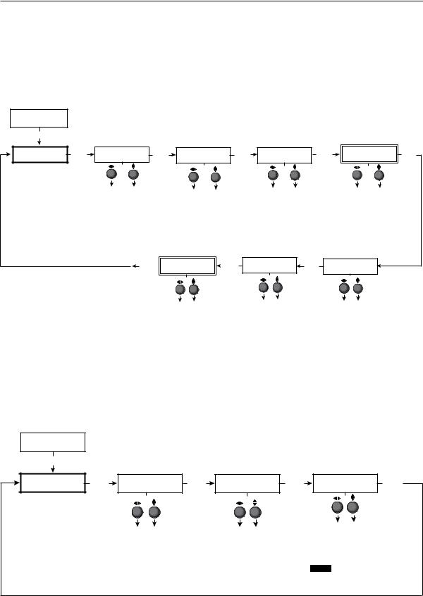
Installation and Operation, cont’d
Picture control
The Picture Control menu includes all of the picture settings for the scaler including positioning, sizing (horizontal and vertical control), brightness and contrast, color saturation, tint, detail (sharpness of the picture), and zooming (see figure 2-12).
The pan feature is only available when zoom is over 100%.
Color, tint and pan controls are available to applicable signals only.
INPUT
CONFIG
MENU |
|
|
|
|
|
|
|
|
|
|
|
Tint adjustment applicable only for |
|
||
|
|
|
|
|
|
|
|
|
|
|
|
|
|||
|
|
|
|
|
|
|
|
|
|
|
|
NTSC composite or S-Video inputs |
|
||
PICTURE |
NEXT |
H POS |
V |
NEXT |
H SIZE |
V |
NEXT |
BRIGHT CONT |
NEXT |
COLOR |
TINT |
NEXT |
|||
CONTROL |
000 |
000 |
1024 |
768 |
064 |
064 |
064 |
064 |
|||||||
|
|
|
|
|
|||||||||||
|
|
Horizontal |
Vertical |
|
Horizontal |
|
Vertical |
|
Brightness |
Contrast |
|
Color |
Tint |
|
|
|
|
position |
position |
|
|
|
Adjust image Adjust image |
|
Adjust color Adjust tint |
|
|||||
|
|
|
sizing |
|
sizing |
|
|
|
|||||||
|
|
Adjust |
Adjust |
|
|
|
|
|
|||||||
|
|
|
Adjust |
|
Adjust |
|
brightness. |
contrast. |
|
of image. |
of image. |
|
|||
|
|
horizontal |
vertical |
|
|
|
|
|
|
||||||
|
|
|
horizontal |
|
vertical |
|
|
|
|
|
|
|
|||
|
|
image |
image |
|
|
|
|
|
|
|
|
|
|||
|
|
|
image |
|
image |
|
|
|
|
|
|
|
|||
|
|
position. |
position. |
|
|
|
|
|
|
|
|
|
|||
|
|
|
sizing. |
|
sizing. |
|
|
|
|
|
|
|
|||
|
|
|
|
|
|
|
|
|
|
|
|
|
|||
Only applicable when zoom is over 100 %
NEXT |
|
H |
PAN V |
|
NEXT |
000 |
000 |
|
|||
|
|
|
|||
Pan
Move the “zoomed” image horizontally or vertically. Available only when zoom is set over 100%.
ZOOM
100% NEXT
Zoom
Allows for 100-200% zoom while the aspect ratio remains unchanged.
DETAIL 064
Detail
Adjust sharpness of the image.
Figure 2-12— Picture control menu
Output configuration
PICTURE CONTROL
MENU
OUTPUT CONFIG
The output configuration menu allows you to select the scaler output rate from different resolutions, refresh rates, sync types (RGBHV, RGBS, RGsB and
Y, B-Y, R-Y), and sync polarity.
NEXT |
RESOLUTION |
NEXT |
|
FORMAT |
NEXT |
|
H SYNC V |
NEXT |
|
1024x768@60 |
|
RGBHV |
|
NEG |
NEG |
||||
|
|
|
|
|
|
||||
Resolution refresh rate |
|
Output type |
|
Sync polarity combinations |
|||||
|
|
• |
H Neg |
V Neg (default) |
|||||
• |
See the scaler output table on next page |
• RGBHV (default) |
|
• |
H Neg |
V Pos |
|
||
|
for available combinations of resolutions |
• |
RGBS |
|
• |
H Pos |
V Neg |
|
|
|
and refresh rates. |
|
• |
RGsB |
|
• H Pos |
V Pos |
|
|
Default: 1024 x 768@60 Hz |
|
• Y, R-Y, B-Y |
|
|
|||||
|
|
|
|
|
|
||||
NOTE This information only appears when the sync polarity is applicable and is based on the selected output format.
Figure 2-13— Output Configuration menu
2-14 DVS 304 • Installation and Operation
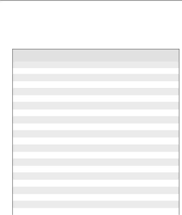
Resolution and refresh rates
Rotate the Adjust horizontal ([) knob while in this submenu to select one of the available combinations of output resolutions and refresh (vertical scanning) rates.
Rotate the Adjust vertical ({) knob while in this submenu to select one of the available refresh rates.
The default resolution and rate for the DVS 304 is 1024 x 768 @ 60Hz.
Available Scaler Output Resolutions and Rates
Resolution |
24 Hz |
50 Hz |
60 Hz |
72 Hz |
75 Hz |
96 Hz |
100 Hz |
120 Hz |
|
|
|
|
|
|
|
|
|
640 x 480 |
|
X |
X |
X |
|
X |
X |
X |
800 x 600 |
|
X |
X |
X |
|
X |
X |
X |
852 x 480 |
|
X |
X |
|
|
|
|
|
|
|
|
|
|
|
|
|
|
1024 x 768 |
|
X |
X |
X |
|
X |
|
|
|
|
|
|
|
|
|
|
|
1024 x 852 |
|
X |
X |
X |
|
X |
|
|
|
|
|
|
|
|
|
|
|
1024 x 1024 |
|
X |
X |
X |
|
|
|
|
|
|
|
|
|
|
|
|
|
1280 x 768 |
|
X |
X |
X |
|
X |
|
|
|
|
|
|
|
|
|
|
|
1280 x 1024 |
|
X |
X |
X |
|
|
|
|
|
|
|
|
|
|
|
|
|
1360 x 765 |
|
X |
X |
X |
|
|
|
|
|
|
|
|
|
|
|
|
|
1365 x 768 |
|
X |
X |
X |
|
|
|
|
|
|
|
|
|
|
|
|
|
1365 x 1024 |
|
X |
X |
|
|
|
|
|
|
|
|
|
|
|
|
|
|
1366 x 768 |
|
X |
X |
X |
|
|
|
|
|
|
|
|
|
|
|
|
|
1400 x1050 |
|
X |
X |
|
|
|
|
|
|
|
|
|
|
|
|
|
|
1600 x 1200 |
|
X |
X |
|
|
|
|
|
|
|
|
|
|
|
|
|
|
480p |
|
|
X |
|
|
|
|
|
|
|
|
|
|
|
|
|
|
576p |
|
X |
|
|
|
|
X |
|
|
|
|
|
|
|
|
|
|
720p |
|
X |
X |
|
|
|
|
|
|
|
|
|
|
|
|
|
|
1080i |
|
X |
X |
|
|
|
|
|
|
|
|
|
|
|
|
|
|
1080p |
X |
X |
X |
|
|
|
|
|
|
|
|
|
|
|
|
|
|
1440 x 900 |
|
|
X |
|
X |
|
|
|
|
|
|
|
|
|
|
|
|
1680 x 1050 |
|
|
X |
|
|
|
|
|
|
|
|
|
|
|
|
|
|
1280 x 800 |
|
X |
X |
|
|
|
|
|
|
|
|
|
|
|
|
|
|
Output Signal
Using either the Adjust horizontal ([) or Adjust vertical ({) knob, select the output video format required by the display: RGBHV (default); RGBS; RGsB; Y, R-Y, B-Y.
Sync Polarity
The display or projector may require a particular combination of horizontal (H) and vertical (V) sync signal polarities.
Select the appropriate combination of positive or negative H and V sync by rotating either the Adjust horizontal ([) or Adjust vertical ({) knob.
NIf the previous output signal was specified as RGsB or Y, R-Y, B-Y, or RGBS, this submenu will not be displayed because this menu is only active for RGBHV.
DVS 304 • Installation and Operation 2-15
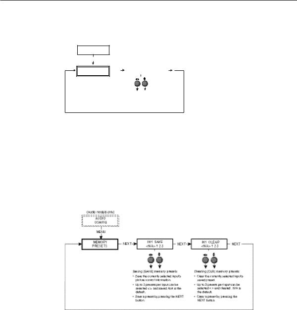
Installation and Operation, cont’d
Audio configuration (DVS 304 A and DVS 304 AD only)
Audio Configuration allows the input level to be adjusted between –15 dB to +9 dB for each audio input.
OUTPUT
CONFIG
MENU
AUDIO |
|
NEXT |
IN1 LEVEL |
|
NEXT |
CONFIG |
|
0dB |
|
||
|
|
|
|
(audio models only)
Input level
Adjust the input gain/attenuation from -15dB to +9dB of the selected input.
Figure 2-14 — Audio configuration menu
Volume control is available through SIS commands or IR remote control.
Memory preset
The memory preset feature saves the current values for image parameters such as color, tint, contrast, brightness, detail, aspect ratio, horizontal start, vertical start, horizontal active, vertical active, phase, total pixels, horizontal position, vertical position, horizontal size, vertical size and zoom.
The following flowchart provides an overview of the Memory Preset submenus and the options for each setting.
Figure 2-15 — Memory present menu
N The presets will only save the sizing, centering, and picture control information.
Save memory preset
From this submenu, the picture control information for the currently selected input can be saved to memory. Up to three memory presets can be saved per input.
1. |
Using either the Adjust horizontal ([) or Adjust vertical ({) knob, select (< >) |
|
either N/A, 1, 2, or 3 to select a preset. The default is <N/A>. |
2. |
To save the preset, press the Next button. |
NThe presets are saved in nonvolatile memory, so powering down the DVS 304 will not lose the presets. Saving a preset by pressing the Next button will also advance to the next submenu (Clear memory preset).
To exit the Save memory preset function without saving a preset, press Menu.
2-16 DVS 304 • Installation and Operation

Clear (CLR) memory preset
From this submenu, up to three saved presets for the currently selected input can be cleared from memory.
1. Using either the Adjust horizontal ([) or Adjust vertical ({) knob, select (< >) either N/A, 1, 2, or 3 to select a preset. The default is <N/A>.
2. To clear the preset, press the Next button.
NClearing a preset by pressing the Next button will also cause a return to the Memory Preset menu.
To exit the Clear memory preset function without clearing a preset, press Menu.
Recalling a preset
Recalling a saved preset requires that the desired input be currently selected and that the input button be pressed successively to activate each saved preset (up to three). Each saved preset will display the message “Input #X Memory Y”, where “X” refers to the input (1 to 4) and “Y” refers to the preset (1 to 3).
In the absence of any saved presets, the “Input #X Memory Y” message will not be displayed for those presets.
NThe presets are specific to a selected output rate. If the output rate is subsequently changed, the previously saved preset will have no effect on the video output. However, if the original output rate is later restored for a saved preset, the preset will re-apply to that output rate.
Input preset
Input preset saves current values for parameters such as input type, color, tint, contrast, brightness, detail, aspect ratio, horizontal start, vertical start, horizontal active, vertical active, phase, total pixels, horizontal position, vertical position, horizontal size, vertical size, zoom, and OSD text.
IP configuration
The IP Configuration menu displays the IP address of the unit, the Subnet mask, and Gateway IP address.
MEMORY
PRESETS
MENU |
|
|
|
|
|
|
|
|
|
|
|
|
|
|
|
|
|
|
|
|
|
|
|
|
|
|
|
|
|
|
|
|
|
|
|
|
|
|
|
|
|
|
|
|
|
|
|
|
|
|
|
|
|
|
|
|
|
|
|
|
|
|
|
|
|
|
|
|
|
|
|
|
|
|
|
IP |
|
NEXT |
|
|
I 196.168 |
|
NEXT |
|
|
S 255.255 |
|
NEXT |
|
|
G 000.000 |
|
NEXT |
|
CONFIG |
|
|
|
|
P 254.254 |
|
|
|
|
M 000.000 |
|
|
|
|
M 000.000 |
|
|
|
|
|
|
|
|
|
View IP address |
|
|
|
|
View the subnet mask |
|
|
|
|
View gateway IP address |
||
|
|
|
|
|
|
of the unit. |
|
|
|
|
of the unit. |
|
|
|
|
of the unit. |
|
|
Figure 2-16— IP Configuration menu
To change an IP address, do the following:
1.Press and hold the Input 4 and Next buttons simultaneously for 2 seconds. This introduces the Setup mode.
2.Change the flashing octet selection by using the Adjust vertical ({) knob. Change the selection numbers by using Adjust horizontal ([) knob.
3.Press the Menu button to return to the IP address setup and the Next button to select another address setup.
4.Press the Menu button to save and exit.
The IP configuration menu “times out” if there is no activity for over 10 seconds.
DVS 304 • Installation and Operation 2-17
 Loading...