


 Loading...
User Guide
Speakers
CS 26T and CS 120P
CS 1226T SpeedMount Ceiling Speaker System
68-2161-01 Rev. A
08 13

Safety Instructions
Safety Instructions • English
WARNING: This symbol,  , when used on the product, is intended to alert the user of the presence of uninsulated dangerous voltage within the product’s enclosure that may present a risk of electric shock.
ATTENTION: This symbol,  , when used on the product, is intended to alert the user of important operating and maintenance (servicing) instructions in the literature provided with the equipment.
For information on safety guidelines, regulatory compliances, EMI/EMF compatibility, accessibility, and related topics, see the Extron Safety and Regulatory Compliance Guide, part number 68-290-01, on the Extron website, www.extron.com.
Chinese Simplified

 (
(
EMI/EMFExtron www.extron.cn Extron68-290-01
Instructions de sécurité • Français
AVERTISSEMENT: Ce pictogramme,  , lorsqu’il est utilisé sur le produit, signale à l’utilisateur la présence à l’intérieur du boîtier du produit d’une tension électrique dangereuse susceptible de provoquer un choc électrique.
ATTENTION: Ce pictogramme,  , lorsqu’il est utilisé sur le produit, signale à l’utilisateur des instructions d’utilisation ou de maintenance importantes qui se trouvent dans la documentation fournie avec le matériel.
Pour en savoir plus sur les règles de sécurité, la conformité à la réglementation, la compatibilité EMI/EMF, l’accessibilité, et autres sujets connexes, lisez les informations de sécurité et de conformité Extron, réf. 68- 290-01, sur le site Extron, www.extron.fr.
Sicherheitsanweisungen • Deutsch
WARNUNG: Dieses Symbol  auf dem Produkt soll den Benutzer darauf aufmerksam machen, dass im Inneren des Gehäuses dieses Produktes gefährliche Spannungen herrschen, die nicht isoliert sind und die einen elektrischen Schlag verursachen können.
VORSICHT: Dieses Symbol  auf dem Produkt soll dem Benutzer in der im Lieferumfang enthaltenen Dokumentation besonders wichtige Hinweise zur Bedienung und Wartung (Instandhaltung) geben.
Weitere Informationen über die Sicherheitsrichtlinien, Produkthandhabung, EMI/EMF-Kompatibilität, Zugänglichkeit und verwandte Themen finden Sie in den Extron-Richtlinien für Sicherheit und Handhabung (Artikelnummer 68- 290-01) auf der Extron-Website, www.extron.de.
Instrucciones de seguridad • Español
ADVERTENCIA: Este símbolo,  , cuando se utiliza en el producto, avisa al usuario de la presencia de voltaje peligroso sin aislar dentro del producto, lo que puede representar un riesgo de descarga eléctrica.
ATENCIÓN: Este símbolo,  , cuando se utiliza en el producto, avisa al usuario de la presencia de importantes instrucciones de uso
y mantenimiento recogidas en la documentación proporcionada con el equipo.
Para obtener información sobre directrices de seguridad, cumplimiento de normativas, compatibilidad electromagnética, accesibilidad y temas
relacionados, consulte la Guía de cumplimiento de normativas y seguridad de Extron, referencia 68-290-01, en el sitio Web de Extron, www.extron.es.
Chinese Traditional
: 

EMI/EMFExtron www.extron.cn Extron
68-290-01
Japanese
: 
:  ( )
( )
EMI/EMFwww.extron.jp
Extron Safety and Regulatory Compliance Guide (P/N 68-290-01)
Korean
:  , ,.
, ,.
:  , ,( ) .
, , EMI/EMF , ,Extron (www.extron.co.kr) Extron , 68-290-01 .
FCC Class A Notice
This equipment has been tested and found to comply with the limits for a Class A digital device, pursuant to part 15 of the FCC rules. The Class A limits provide reasonable protection against harmful interference when the equipment is operated in a commercial environment. This equipment generates, uses, and can radiate radio frequency energy and, if not installed and used in accordance with the instruction manual, may cause harmful interference to radio communications. Operation of this equipment in a residential area is likely to cause interference; the user must correct the interference at his own expense.
NOTE: For more information on safety guidelines, regulatory compliances, EMI/EMF compatibility, accessibility, and related topics, see the “Extron Safety and Regulatory Compliance
Guide” on the Extron website.
Copyright
© 2013 Extron Electronics. All rights reserved.
Trademarks
All trademarks mentioned in this guide are the properties of their respective owners.
The following registered trademarks®, registered service marks(SM), and trademarks(TM) are the property of RGB Systems, Inc. or Extron Electronics:
Registered Trademarks(®)
AVTrac, Cable Cubby, CrossPoint, eBUS, EDID Manager, EDID Minder, Extron, Flat Field, GlobalViewer, Hideaway, Inline, IP Intercom, IP Link, Key Minder, LockIt, MediaLink, PlenumVault, PoleVault, PowerCage, PURE3, Quantum, SoundField, SpeedMount, SpeedSwitch, System Integrator, TeamWork, TouchLink, V Lock, VersaTools, VN Matrix, VoiceLift, WallVault, WindoWall, XTP and XTP Systems
Registered Service Mark(SM) : S3 Service Support Solutions
Trademarks (™)
AAP, AFL (Accu Rate Frame Lock), ADSP (Advanced Digital Sync Processing), AIS (Advanced Instruction Set), Auto Image, CDRS (Class D Ripple Suppression), DDSP (Digital Display Sync Processing), DMI (Dynamic Motion Interpolation), Driver Configurator, DSP Configurator, DSVP (Digital Sync Validation Processing), FastBite, FOXBOX, IP Intercom HelpDesk, MAAP, MicroDigital, ProDSP, QS-FPC (QuickSwitch Front Panel Controller), Scope Trigger, SIS, Simple Instruction Set, Skew Free, SpeedNav, Triple Action Switching, XTRA, ZipCaddy, ZipClip
Conventions Used in this Guide
Notifications
The following notifications are used in this guide:
WARNING: A warning indicates a situation that has the potential to result in death or severe injury.
ATTENTION: Attention indicates a situation that may damage or destroy the product or associated equipment.
NOTE: A note draws attention to important information.
Specifications Availability
Product specifications are available on the Extron website, www.extron.com.

Contents
Introduction............................................................ |
1 |
About this Guide................................................. |
1 |
Overview............................................................. |
1 |
Features.............................................................. |
1 |
Application Example............................................ |
2 |
Installation.............................................................. |
3 |
Installation Considerations................................... |
3 |
Installation Configurations................................... |
3 |
Installing the CS 1226T System — Single |
|
Installer.............................................................. |
4 |
Installing the CS 120P in a Suspended |
|
Ceiling — Division of Labor.............................. |
15 |
Installing the CS 26T in a Suspended |
|
Ceiling — Division of Labor.............................. |
20 |
Installing the CS 120P in a Hard Ceiling............. |
26 |
CS 26T and CS 120P User Guide • Contents |
v |

CS 26T and CS 120P User Guide • Contents vi

Introduction
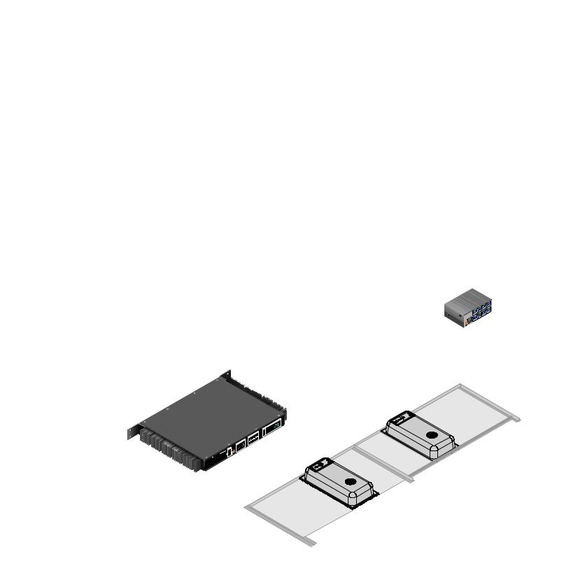
This section gives an overview of the Extron CS 1226T SpeedMount Ceiling Speaker System, consisting of the CS 26T speakers and CS 120P enclosure. It also provides a list of system features and an application diagram. Topics include:
•About this Guide
•Overview
•Features
•Application Example
About this Guide
This guide describes the Extron CS 1226T Speaker System, the CS 26T speaker pair and the CS 120P enclosure and provides instructions for installing all components of the system in different types of ceilings.
Overview
The CS 1226T system features a low profile design that houses a 6.5-inch woofer and a 0.75-inch tweeter (CS 26T) contained in a UL 2043 rated enclosure (CS 120P) designed for use in plenum rated ceiling spaces.
This unique speaker system splits installation into two phases, rough-in and finish, allowing the installer to “reserve” space for the speaker system by installing the CS 120P back can and then later installing the CS 26T speaker. This two-step process (division of labor) is especially useful when multiple installers are involved. The CS 120P can be installed by the low voltage contractor while the CS 26T can be installed by the AV systems contractor.
Features
•US and metric ceiling grids — The CS 120P enclosure can be installed in both U.S. and metric ceiling grid systems (for metric systems, the CS 120P end tabs are cut off).
•UL 2043 listed — The CS 1226T is UL 2043 listed (only when the CS 26T is used with the CS 120P).
NOTE: The use of any other back can other than the CS 120P or those provided by
Extron voids the UL 2043 rating.
•Optional open back configuration — The CS 26T can be used without the CS 120P by reconfiguring the attached bass port plate (allowing the CS 26T to function as an open back speaker).
NOTE: When the CS 26T is used without the CS 120P, it is not suitable for air handling spaces and is not UL 2043 rated.
•New dog-leg design — The new dog-leg design eliminates jamming during installation.
•Low profile enclosure — The low profile enclosure is compatible with plenum environments where overhead space may be limited.
CS 26T and CS 120P User Guide • Introduction |
1 |
•Selectable taps — The rotary tap selector switch, located behind the grille, sets the speaker to operate in either 8-ohm direct or 70 volt /100 volt operation with 16, 8, 4, 2, and 1 watt taps.
•Magnetic grille — Magnets spaced around the grille edge enable it to be easily attached and to remain firmly in place.
Application Example
The illustration below is one example of configuring a system using the CS 1226T.
Desk Microphones
OUTPUT
INPUT
AUDIO
OUTPUT
I
N
P
U
T
IN1508
Scaling Presentation
Switcher
 PC
PC
Extron |
|
|
TLP 700TV |
Ethernet |
|
7" TouchLink |
||
|
||
Tabletop |
|
|
Touchpanel |
|
|
|
TCP/IP |
|
|
Network |
|
Extron |
|
|
IPL 250 |
|
|
IP Link Control |
|
|
Processor |
|
|
64 |
|
|
DMP |
|
|
LAN RESET |
|
|
I/O |
|
RS-232 |
INPUTS |
U |
MIC/LINE |
O |
P |
|
|
T |
|
U |
|
T |
|
S |
POWER
Digital Matrix
Processor

 ∞
∞  ∞ ∞
∞ ∞
Extron
XPA 2003C 70V
Combo Power Ampli er
Extron
CS 1226T
SpeedMount Ceiling
Speaker System
Extron
SI 26
Surface-Mount
Speakers
Figure 1. Application Diagram of a CS 1226T Installation
CS 26T and CS 120P User Guide • Introduction |
2 |
Installation
This section provides instructions for installing the CS 26T speakers and the CS 120P enclosure. Topics include:
•Installation Considerations
•Installation Configurations
•Installing the CS 1226T — Single Installer
•Installing the CS 120P in a Suspended Ceiling — Division of Labor
•Installing the CS 26T in a Suspended Ceiling — Division of Labor
•Installing CS 120P in a Hard Ceiling
Installation Considerations
WARNING: Risk of severe bodily injury from falling or sharp equipment. |
Installation and service must be performed by authorized personnel only. |
•All wiring and electrical connections must conform to all applicable building codes and local ordinances.
•Installation in a plenum-rated environment requires plenum rated cable or conduit.
•If using secondary support cables, the installer provides the cables.
Installation Configurations
The CS 26T can be configured in the following ways:
•Open-back: For configurations in which the CS 120P is not used, use the C-ring accessory, available at www.extron.com. The C-ring spreads out the clamping force of the dog-legs when used in drop ceilings and gypsum ceilings.
•Using the CS 120P: When used with the CS 120P, the CS 26T can be placed in plenum environments. This is the only configuration that is UL 2043 rated.
NOTE: The CS 120P can be ordered separately or as part of the CS 1226T kit.
For hard ceiling installations, see Installing the CS 120P in a Hard Ceiling on page 26.
CS 26T and CS 120P User Guide • Installation |
3 |
Installing the CS 1226T System — Single Installer
If a single installer is installing the CS 1226T system, follow this procedure for the entire system:
 NOTE: The ceiling grid must be installed before the installation of the CS 1226T begins.
• Verify if fiberglass ceiling tiles are being used (see step 2 below and step 11 on
page 7 for details).
• The grid face must be at least 15/16 inch (24 mm) for proper installation of the
CS 120P (see step 20 on page 13 for details on suspending the enclosure on a
smaller grid face).
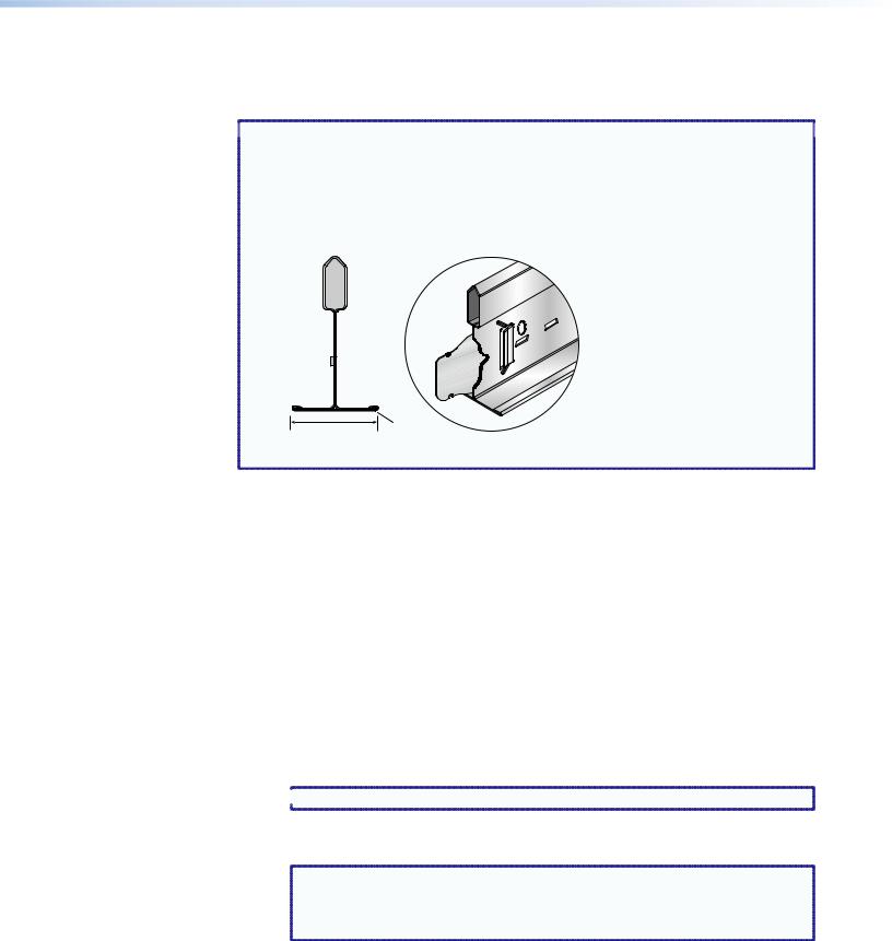
Side View
Grid Face
15/16" (24 mm)
Figure 2. Grid Face Example
1.Disconnect power — Power down all attached devices before proceeding.
2.Verify the space where the system will be installed — Ensure that there is sufficient clearance above the ceiling tile for the unit to be installed.
3.Cut a hole for the CS 26T speaker — Use the provided cutout template to outline the hole to be cut in the ceiling tile as described below.
a.Remove the ceiling tile.
b.To find the center of the tile, use a tape measure to measure the space between two opposite corners, and mark the half-way point.
c.Position the center hole of the cutout template directly over the center of the tile that you marked in step 3b.
d.Using the provided cutout template, trace a circle on the ceiling tile as follows:
For installations in ceiling tiles that are NOT fiberglass or when installing the speakers in an open back configuration: Trace a circle around the CS 26T cutout template.
 NOTE: The fiberglass tile adapters are not needed and can be discarded.
For installations in 1-inch (0.25 cm) thick fiberglass ceiling tiles with the
CS 120P:
NOTE: A set of fiberglass tile adapters is provided with both the CS 26T and |
the CS 120P. Only one set is needed to install the CS 26T with the CS 120P |
kit in a 1-inch (0.25 cm) thick fiberglass tile. The adapter works only with |
1-inch (0.25 cm) thick fiberglass tile. |
i.Place the fiberglass tile adapter around the outer diameter of the template that was positioned in step 3c.
ii.Trace a circle around the outer diameter of the adapter.
CS 26T and CS 120P User Guide • Installation |
4 |
Loading...