


 Loading...
Setup Guide
Matrix Switchers
DXP DVI Pro
DXP HDMI
DVI and HDMI
Matrix Switchers
68-1370-50 Rev. C
03 12
Safety Instructions • English
This symbol is intended to alert the user of important operating and maintenance (servicing) instructions in the literature provided with the equipment.
This symbol is intended to alert the user of the presence of uninsulated dangerous voltage within the product’s enclosure that may present a risk of electric shock.
Caution
Read Instructions • Read and understand all safety and operating instructions before using the equipment.
Retain Instructions • The safety instructions should be kept for future reference.
Follow Warnings • Follow all warnings and instructions marked on the equipment or in the user information.
Avoid Attachments • Do not use tools or attachments that are not recommended by the equipment manufacturer because they may be hazardous.
Consignes de Sécurité •Français
Ce symbole sert à avertir l’utilisateur que la documentation fournie avec le matériel contient des instructions importantes concernant l’exploitation et la maintenance (réparation).
Ce symbole sert à avertir l’utilisateur de la présence dans le boîtier de l’appareil de tensions dangereuses non isolées posant des risques d’électrocution.
Attention
Lire les instructions• Prendre connaissance de toutes les consignes de sécurité et d’exploitation avant d’utiliser le matériel.
Conserver les instructions• Ranger les consignes de sécurité afin de pouvoir les consulter à l’avenir.
Respecter les avertissements • Observer tous les avertissements et consignes marqués sur le matériel ou présentés dans la documentation utilisateur.
Eviter les pièces de fixation • Ne pas utiliser de pièces de fixation ni d’outils non recommandés par le fabricant du matériel car cela risquerait de poser certains dangers.
Sicherheitsanleitungen • Deutsch
Dieses Symbol soll dem Benutzer in der im Lieferumfang enthaltenen Dokumentation besonders wichtige Hinweise zur Bedienung und Wartung (Instandhaltung) geben.
Dieses Symbol soll den Benutzer darauf aufmerksam machen, daß im Inneren des Gehäuses dieses Produktes gefährliche Spannungen, die nicht isoliert sind und
die einen elektrischen Schock verursachen können, herrschen.
Achtung
Lesen der Anleitungen • Bevor Sie das Gerät zum ersten Mal verwenden, sollten Sie alle Sicherheits-und Bedienungsanleitungen genau durchlesen und verstehen.
Aufbewahren der Anleitungen • Die Hinweise zur elektrischen Sicherheit des Produktes sollten Sie aufbewahren, damit Sie im Bedarfsfall darauf zurückgreifen können.
Befolgen der Warnhinweise • Befolgen Sie alle Warnhinweise und Anleitungen auf dem Gerät oder in der Benutzerdokumentation.
Keine Zusatzgeräte • Verwenden Sie keine Werkzeuge oder Zusatzgeräte, die nicht ausdrücklich vom Hersteller empfohlen wurden, da diese eine Gefahrenquelle darstellen können.
Warning
Power sources • This equipment should be operated only from the power source indicated on the product. This equipment is intended to be used with a main power system with a grounded (neutral) conductor. The third (grounding) pin is a safety feature, do not attempt to bypass or disable it.
Power disconnection • To remove power from the equipment safely, remove all power cords from the rear of the equipment, or the desktop power module (if detachable), or from the power source receptacle (wall plug).
Power cord protection • Power cords should be routed so that they are not likely to be stepped on or pinched by items placed upon or against them.
Servicing • Refer all servicing to qualified service personnel. There are no user-serviceable parts inside. To prevent the risk of shock, do not attempt to service this equipment yourself
because opening or removing covers may expose you to dangerous voltage or other hazards.
Slots and openings • If the equipment has slots or holes in the enclosure, these are provided to prevent overheating of sensitive components inside. These openings must never be blocked by other objects.
Lithium battery • There is a danger of explosion if battery is incorrectly replaced. Replace it only with the same or equivalent type recommended by the manufacturer. Dispose of used batteries according to the manufacturer’s instructions.
Avertissement
Alimentations • Ne faire fonctionner ce matériel qu’avec la source d’alimentation indiquée sur l’appareil. Ce matériel doit être utilisé avec une alimentation principale comportant un fil de terre (neutre). Le troisième contact (de mise à la terre) constitue un dispositif de sécurité : n’essayez pas de la contourner ni de la désactiver.
Déconnexion de l’alimentation• Pour mettre le matériel hors tension sans danger, déconnectez tous les cordons d’alimentation de l’arrière de l’appareil ou du module d’alimentation de bureau (s’il est amovible) ou encore de la prise secteur.
Protection du cordon d’alimentation • Acheminer les cordons d’alimentation de manière à ce que personne ne risque de marcher dessus et à ce qu’ils ne soient pas écrasés ou pincés par des objets.
Réparation-maintenance • Faire exécuter toutes les interventions de réparation-maintenance par un technicien qualifié. Aucun des éléments internes ne peut être réparé par l’utilisateur. Afin d’éviter tout danger d’électrocution, l’utilisateur ne doit pas essayer de procéder luimême à ces opérations car l’ouverture ou le retrait des couvercles risquent de l’exposer à de hautes tensions et autres dangers.
Fentes et orifices • Si le boîtier de l’appareil comporte des fentes ou des orifices, ceux-ci servent à empêcher les composants internes sensibles de surchauffer. Ces ouvertures ne doivent jamais être bloquées par des objets.
Lithium Batterie • Il a danger d’explosion s’ll y a remplacment incorrect de la batterie. Remplacer uniquement avec une batterie du meme type ou d’un ype equivalent recommande par le constructeur. Mettre au reut les batteries usagees conformement aux instructions du fabricant.
Vorsicht
Stromquellen • Dieses Gerät sollte nur über die auf dem Produkt angegebene Stromquelle betrieben werden. Dieses Gerät wurde für eine Verwendung mit einer Hauptstromleitung mit einem geerdeten (neutralen) Leiter konzipiert. Der dritte Kontakt ist für einen Erdanschluß, und stellt eine Sicherheitsfunktion dar. Diese sollte nicht umgangen oder außer
Betrieb gesetzt werden.
Stromunterbrechung • Um das Gerät auf sichere Weise vom Netz zu trennen, sollten Sie alle Netzkabel aus der Rückseite des Gerätes, aus der externen Stomversorgung (falls dies möglich ist) oder aus der Wandsteckdose ziehen.
Schutz des Netzkabels • Netzkabel sollten stets so verlegt werden, daß sie nicht im
Weg liegen und niemand darauf treten kann oder Objekte daraufoder unmittelbar dagegengestellt werden können.
Wartung • Alle Wartungsmaßnahmen sollten nur von qualifiziertem Servicepersonal durchgeführt werden. Die internen Komponenten des Gerätes sind wartungsfrei. Zur Vermeidung eines elektrischen Schocks versuchen Sie in keinem Fall, dieses Gerät selbst öffnen, da beim Entfernen der Abdeckungen die Gefahr eines elektrischen Schlags und/oder andere Gefahren bestehen.
Schlitze und Öffnungen • Wenn das Gerät Schlitze oder Löcher im Gehäuse aufweist, dienen diese zur Vermeidung einer Überhitzung der empfindlichen Teile im Inneren. Diese
Öffnungen dürfen niemals von anderen Objekten blockiert werden.
Litium-Batterie • Explosionsgefahr, falls die Batterie nicht richtig ersetzt wird. Ersetzen Sie verbrauchte Batterien nur durch den gleichen oder einen vergleichbaren Batterietyp, der auch vom Hersteller empfohlen wird. Entsorgen Sie verbrauchte Batterien bitte gemäß den Herstelleranweisungen.
Instrucciones de seguridad • Español
Este símbolo se utiliza para advertir al usuario sobre instrucciones importantes de operación y mantenimiento (o cambio de partes) que se desean destacar en el contenido de la documentación suministrada con los equipos.
Este símbolo se utiliza para advertir al usuario sobre la presencia de elementos con voltaje peligroso sin protección aislante, que puedan encontrarse dentro de la caja o alojamiento del producto, y que puedan representar riesgo de electrocución.
Precaucion
Leer las instrucciones • Leer y analizar todas las instrucciones de operación y seguridad, antes de usar el equipo.
Conservar las instrucciones • Conservar las instrucciones de seguridad para futura consulta.
Obedecer las advertencias • Todas las advertencias e instrucciones marcadas en el equipo o en la documentación del usuario, deben ser obedecidas.
Evitar el uso de accesorios •No usar herramientas o accesorios que no sean especificamente recomendados por el fabricante, ya que podrian implicar riesgos.
Advertencia
Alimentación eléctrica • Este equipo debe conectarse únicamente a la fuente/tipo de alimentación eléctrica indicada en el mismo. La alimentación eléctrica de este equipo debe provenir de un sistema de distribución general con conductor neutro a tierra. La tercera pata (puesta a tierra) es una medida de seguridad, no puentearia ni eliminaria.
Desconexión de alimentación eléctrica • Para desconectar con seguridad la acometida de alimentación eléctrica al equipo, desenchufar todos los cables de alimentación en el panel trasero del equipo, o desenchufar el módulo de alimentación (si fuera independiente), o desenchufar el cable del receptáculo de la pared.
Protección del cables de alimentación • Los cables de alimentación eléctrica se deben instalar en lugares donde no sean pisados ni apretados por objetos que se puedan apoyar sobre ellos.
Reparaciones/mantenimiento • Solicitar siempre los servicios técnicos de personal calificado. En el interior no hay partes a las que el usuario deba acceder. Para evitar riesgo de electrocución, no intentar personalmente la reparación/mantenimiento de este equipo, ya que al abrir o extraer las tapas puede quedar expuesto a voltajes peligrosos u otros riesgos.
Ranuras y aberturas • Si el equipo posee ranuras o orificios en su caja/alojamiento, es para evitar el sobrecalientamiento de componentes internos sensibles. Estas aberturas nunca se deben obstruir con otros objetos.
Batería de litio • Existe riesgo de explosión si esta batería se coloca en la posición incorrecta. Cambiar esta batería únicamente con el mismo tipo (o su equivalente) recomendado por el fabricante. Desachar las baterías usadas siguiendo las instrucciones del fabricante.
•
•
•
•
•
•
•
••
•
•
FCC Class A Notice
This equipment has been tested and found to comply with the limits for a Class A digital device, pursuant to part 15 of the FCC Rules. Operation is subject to the following two conditions:
1.This device may not cause harmful interference.
2.This device must accept any interference received, including interference that may cause undesired operation.
The Class A limits are designed to provide reasonable protection against harmful interference when the equipment is operated in a commercial environment. This equipment generates, uses, and can radiate radio frequency energy and, if not installed and used in accordance with the instruction manual, may cause harmful interference to radio communications. Operation of this equipment in a residential area is likely to cause harmful interference, in which case the user will be required to correct the interference at his own expense.
 NOTE: This unit was tested with shielded cables on the peripheral devices. Shielded cables
  must be used with the unit to ensure compliance with FCC emissions limits.
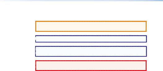
Conventions Used in this Guide
In this user guide, the following are used:
CAUTION: A caution indicates a potential hazard to equipment or data.
 NOTE: A note draws attention to important information.
 TIP: A tip provides a suggestion to make working with the
  application easier.
 WARNING: A warning warns of things or actions that might
  cause injury, death, or other severe consequences.
Copyright
© 2012 Extron Electronics. All rights reserved.
Trademarks
All trademarks mentioned in this guide are the properties of their respective owners.

Contents
Introduction........................................ |
1 |
About this Guide................................ |
1 |
About the DXP DVI Pro and DXP |
|
HDMI Series Matrix Switchers.......... |
1 |
Application Diagram Examples......... |
2 |
Setup.................................................... |
5 |
Setup Procedure................................. |
5 |
Rear Panels and Connections............. |
6 |
Front Panel Config Port................... |
10 |
Operation.......................................... |
13 |
Front Panel Features........................ |
13 |
Operations........................................ |
15 |
Creating a Tie............................... |
15 |
Saving or Recalling a Preset......... |
16 |
Locking and Unlocking the |
|
Front Panel (Executive |
|
Modes) ......................................... |
16 |
Viewing Ties (and Muting |
|
Outputs) ....................................... |
18 |
Selecting the RS-232/RS-422 Port |
|
Protocol and Baud Rate (Rear |
|
Panel) ........................................... |
19 |
Remote Control................................ |
21 |
Establishing a Network |
|
(Ethernet) Connection.................... |
21 |
Connection Timeouts................... |
22 |
Number of Connections............... |
22 |
Verbose Mode.............................. |
22 |
SIS Commands................................... |
22 |
Host-to-switcher Instructions....... |
22 |
EDID (Extended Display |
|
Identification Data) ..................... |
23 |
Command and Response Table |
|
for SIS Commands........................... |
25 |
Installing and Starting the Matrix |
|
Switchers Control Program............ |
33 |
Installing the Program................. |
33 |
Starting the Program................... |
34 |
Accessing the HTML Pages............... |
36 |
Loading the Start-up Page........... |
36 |
Using the Web Pages to |
|
Configure the DXP...................... |
38 |
DXP DVI Pro and DXP HDMI Series • Contents v

vi DXP DVI Pro and DXP HDMI Series • Contents

Introduction
This section gives an overview of the Extron DXP 44/48/84/88 DVI Pro and DXP 44/48/84/88 HDMI Series Digital Matrix Switchers and provides application examples. The following topics are covered:
•• About this Guide
•• About the DXP DVI Pro and DXP HDMI Series Matrix Switchers
•• Application Diagram Examples
 NOTE: For more information on any subject in this guide, see the
DXP DVI Pro and DXP HDMI Series Digital Matrix Switchers 
User Guide, available on the Extron Product Software DVD  or at www.extron.com.
About this Guide
This setup guide allows you to easily and quickly set up and configure your DXP matrix switcher. Step by step instructions show you how to connect the hardware and to perform basic operations using both the front panel controls and selected Simple Instruction Set (SIS™) commands. The guide also shows you how to load and start up the Matrix Switchers Control Program and how to connect to the built-in HTML pages, which you can use to operate the switcher.
The terms “DXP,“ “switcher,” and “DXP switcher” are used interchangeably in this guide to refer to all DXP models.
“DXP DVI Pro” refers to the four DVI models and “DXP HDMI” refers to the four HDMI® models.
About the DXP DVI Pro and DXP HDMI Series Matrix Switchers
The Extron DXP DVI Pro and DXP HDMI series are digital matrix switchers that route single link DVI-D signals or HDMI signals from multiple sources to any or all of up to eight DVIor HDMI-equipped display devices. All DXP matrix switchers support resolutions of up to 1920x1200 and HDTV 1080p/60, and are HDCP-compliant, enabling simultaneous distribution of a single source signal to one or more compliant displays.
The following matrix sizes are available:
•• DXP 44 DVI Pro and DXP 44 HDMI: 4 inputs by 4 outputs
•• DXP 48 DVI Pro and DXP 48 HDMI: 4 inputs by 8 outputs
•• DXP 84 DVI Pro and DXP 84 HDMI: 8 inputs by 4 outputs
•• DXP 88 DVI Pro and DXP 88 HDMI: 8 inputs by 8 outputs
DXP DVI Pro and DXP HDMI Series • Introduction |
1 |
The DXP DVI Pro and DXP HDMI series all provide easy integration in applications that require reliable DVI or HDMI signal routing. (A "DVI Pro" signal is HDCP-compliant; a standard DVI signal is not.)
They include several convenience features common to Extron matrix switchers such as the QuickSwitch Front Panel Controller (QS-FPC™) , global presets, IP Link®, and Ethernet control.
 NOTES: • The DXP DVI Pro fully supports HDMI video and
embedded audio signals when optional Extron
DVI-to-HDMI adapters are used.
• The DXP HDMI fully supports single-link DVI video and embedded audio signals when the optional Extron HDMI-to-DVI adapters are used.
Application Diagram Examples
DVI 201xi Tx
|
|
Display 1 |
|
Display 2 |
|
|
Display 3 |
|
PC |
|
|
|
|
|
|
|
|
Extron |
DVI 201 Rx |
|
|
|
|
|
|
|
|
|
|
|
|
|
|
|
|
DXP DVI Pro Series |
|
|
|
|
|
|
|
|
HDCP-compliant DVI |
|
|
|
|
|
|
|
|
Matrix Switcher |
|
|
|
DVI PRO - HDCP COMPLIANT |
|
|
|
|
|
1 |
2 DVI-D INPUTS |
3 |
4 |
1 |
2 |
DVI-D OUTPUTS 3 |
4 |
|
5 |
6 |
7 |
8 |
5 |
6 |
7 |
8 |
|
C US |
|
|
|
|
|
|
|
Document Camera
DVS 304 DVI
HD Satellite Receiver
Laptop Laptop
|
|
|
|
|
|
DVD Player |
HDMI-DVI Adapters |
|
Blu-ray Player |
||
Figure 1. Typical DXP DVI Pro Application
Display 4
TouchLink™
Control
System
LAN |
RESET |
|
LINK |
TCP/IP |
|
|
ACT |
REMOTE |
RS232/RS422 |
Displays 5 - 8
2 DXP DVI Pro and DXP HDMI Series • Introduction

Display 1 |
Display 3 |
Display 5 |
Display 7 |
|||||||||||
|
|
|
|
|
|
|
|
|
|
|
|
|
|
|
|
|
|
|
|
|
|
|
|
|
|
|
|
|
|
|
|
Display 2 |
|
|
Display 4 |
|
|
Display 6 |
|
|
Display 8 |
|||
|
|
|
|
|
|
|
|
|
|
|
|
|
|
|
|
Extron |
|
|
|
|
|
|
|
|
|
|
|
|
|
|
|
|
|
|
|
|||||||
|
HDMI 201 Tx |
|
|
|
|
|
|
|
|
|
|
|
Extron |
||||||||||||||
|
HDMI Twisted |
|
|
|
|
|
|
|
|
|
|
|
IPL 250 |
||||||||||||||
|
Pair Extender |
|
|
|
|
|
|
|
|
|
|
|
IP Link Ethernet |
||||||||||||||
|
|
|
|
|
|
|
|
|
Extron |
|
|
|
|
Control Processor |
|||||||||||||
|
|
|
|
|
|
|
|
|
|
|
|
|
|
|
|
|
|
|
|
|
|||||||
|
|
|
|
|
|
|
Extron |
DXP HDMI Series |
|
|
|
|
|
|
|
|
|
|
|
|
|||||||
|
|
|
|
|
|
|
|
|
|
|
|
|
|
|
|
|
|
|
|||||||||
|
|
|
|
|
|
|
HDMI 201 Rx |
HDMI Matrix Switchers |
|
|
|
|
|
|
|
|
|
|
|
|
|||||||
Laptop |
|
|
|
|
|
|
HDMI Twisted |
|
|
|
|
|
|
|
|
|
|
|
|
|
|
|
|
|
|
|
|
|
|
|
|
|
|
Pair Extender |
|
|
|
|
|
|
|
|
|
|
|
|
|
|
|
|
|
|
|
||
|
|
|
|
|
|
|
|
|
|
|
|
|
|
|
|
TCP/IP |
|||||||||||
|
|
|
|
|
|
|
|
|
|
|
|
|
|
|
|
||||||||||||
|
|
|
|
|
|
|
|
|
|
|
|
|
|
|
|
||||||||||||
|
|
|
|
|
|
|
|
|
|
|
HD-VTC |
||||||||||||||||
|
|
|
|
|
|
|
|
|
|
|
Network |
||||||||||||||||
|
|
|
|
|
|
|
|
|
|
|
|
|
|
|
|
||||||||||||
|
|
|
|
|
|
|
|
|
|
|
|
|
|
|
|
|
|
|
|
|
Remote User |
||||||
|
|
|
|
|
|
|
|
|
|
|
|
|
|
|
|
|
|
|
|
|
and Administration |
||||||
|
|
|
|
|
|
|
|
|
|
|
|
|
|
|
|
|
|
|
|
|
Control |
||||||
Document Camera |
|
Game Console |
|
|
|
|
|
|
|
|
|
|
|
|
|||||||||||||
|
|
|
|
|
|
|
|
|
|
|
|
|
|
|
|
|
|
|
|
|
|
|
|
||||
|
|
|
|
|
|
|
|
|
|
|
|
|
|
|
|
|
|
|
|
|
|
|
|
||||
Media PC Server |
HD Satellite Receiver |
|
|
|
|
|
|
|
|
|
|
|
|
||||||||||||||
|
|
|
|
|
|
|
|
|
|
|
|
|
|
|
|
PC |
|||||||||||
HD-DVD Player |
Blu-ray Player |
|
|
|
|
|
|
|
|
|
|
|
|
||||||||||||||
Figure 2. Typical DXP HDMI Application
DXP DVI Pro and DXP HDMI Series • Introduction |
3 |

4 DXP DVI Pro and DXP HDMI Series • Introduction
Setup
This section describes the rear panels of the DXP switchers and provides instructions for cabling. It covers the following topics:
•• Setup Procedure
•• Rear Panels and Connections
•• Front Panel Config Port
Setup Procedure
Follow these steps to set up and start operating the DXP switcher. See the "Operation" section for additional configuration procedures you may want to perform to set up the switcher.
1.Turn off power to the input and output devices and disconnect their power cords.
2.Connect DVI or HDMI input devices to the rear panel input connectors (see "B Input connectors" on page 7) .
3.Connect DVI or HDMI output devices to the rear panel output connectors (see "C Output connectors" on page 8) .
4.Change any required button labels (optional) (see "Replacing Button Labels" in the "Reference Information" section of the
DXP DVI Pro and DXP HDMI Series User Guide) .
5.If desired, connect a computer or control system to the Remote RS-232/RS-422 port or to the front panel Config RS-232 port (see "G Remote RS232/RS422 connector" on page 10) .
6.If desired, connect a network WAN or LAN hub, a control system, or a computer to the rear panel Ethernet RJ-45 port (see "D Ethernet port" on page 8) .
7.Plug the DXP switcher into a grounded AC source, and connect power to the input and output devices.
8.Select EDID files to apply to inputs as desired, using SIS commands, the Matrix Switchers Control Program, or the DXP web pages. See "EDID (Extended Display Identification Data)" in the "Remote Control" section, or see the control program help file and the
DXP DVI Pro and DXP HDMI User Guide for details.
9.Create ties as desired (see "Creating a Tie" in the "Operations" section) .
DXP DVI Pro and DXP HDMI Series • Setup |
5 |

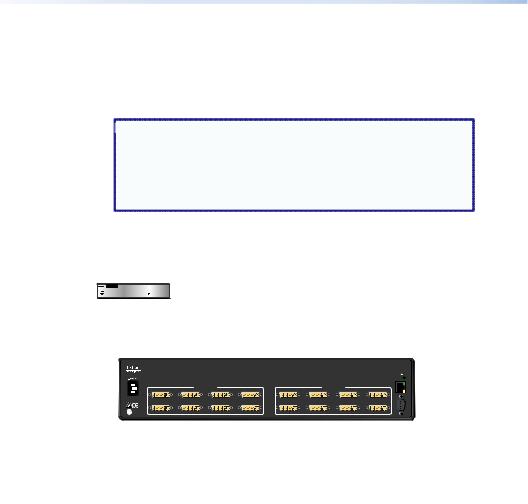
Rear Panels and Connections
Most of the connectors are on the rear panels of the DXP switchers. The following figures show the rear panels of the four DVI models and the four HDMI models.
 NOTE: The illustrations below show DXP 88 DVI Pro and
DXP 88 HDMI models, with 8 input and 8 output connectors. 
The rear panels of the other DXP models are identical to
these models except for the number of inputs and outputs
(see "About the DXP DVI Pro and DXP HDMI Series Matrix
Switchers" in the "Introduction" section for the available matrix sizes) .
1 |
2 |
3 |
|
|
DVI PRO - HDCP COMPLIANT |
1 |
2 |
DVI-D INPUTS 3 |
4 |
1 |
2 |
DVI-D OUTPUTS 3 |
4 |
5 |
6 |
7 |
8 |
5 |
6 |
7 |
8 |
LISTED
C  US1T23I.T.E.
|
|
Figure 3. DXP DVI Pro Rear Panel |
|
|
|
||||
|
1 |
|
2 |
|
|
|
|
3 |
|
|
|
|
|
|
|
HDMI - HDCP COMPLIANT |
|
|
|
|
1 |
2 |
HDMI INPUTS |
3 |
4 |
1 |
2 |
HDMI OUTPUTS 3 |
4 |
|
5 |
6 |
|
7 |
8 |
5 |
6 |
7 |
8 |
|
LISTED |
|
|
|
|
|
|
|
|
C |
USI.T.E.1T23 |
|
|
|
|
|
|
|
|
4 |
|
LAN |
RESET |
|
|
|
LINK |
|
ACT |
REMOTE |
RS232/RS422 |
4 |
|
LAN |
RESET |
|
|
|
LINK |
|
ACT |
REMOTE |
RS232/RS422 |
5
6
7
5
6
7
Figure 4. DXP HDMI Rear Panel
 WARNING: Remove power from the system before making any
  connections.
CAUTION: Use electrostatic discharge precautions (be electrically grounded) when making connections. Electrostatic discharge (ESD) can damage equipment, although you may not feel, see, or hear it.
AAC power connector — Plug a standard IEC power cord into this connector to connect the switcher to a 100 VAC to 240 VAC, 50 or 60 Hz power source.
6 DXP DVI Pro and DXP HDMI Series • Setup
BInput connectors —
•• DVI Pro series: Connect DVI-D source devices to these female 29-pin DVI-I input connectors. Only single-link DVI-D signals are supported.
•• HDMI series: Connect HDMI source devices to these female 19-pin type A HDMI input connectors.
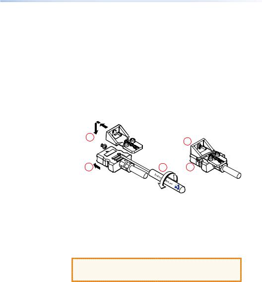
LockIt™ cable lacing brackets, one for each HDMI input and output connector, are provided with the DXP HDMI. These brackets can be used to secure the HDMI cables to the DXP connectors to reduce stress on the HDMI connectors and prevent signal loss due to loose cable connections.
To securely fasten an HDMI cable to the DXP using LockIt brackets:
1. Plug the HDMI cable into the panel connection.
3 |
|
4 |
|
|
|
1 |
2 |
5 |
Figure 5. Installing the LockIt Lacing Bracket
2.Loosen the HDMI connection mounting screw from the panel enough to allow the LockIt lacing bracket to be placed over it. The screw does not have to be removed.
3.Place the LockIt lacing bracket on the screw and against the HDMI connector, then tighten the screw to secure the bracket.
CAUTION: Do not overtighten the HDMI connector mounting screw. The shield to which it fastens is very thin and can easily be stripped.
4.Loosely place the included tie wrap around the HDMI connector and the LockIt lacing bracket as shown.
5.While holding the connector securely against the lacing bracket, use pliers or similar tools to tighten the tie wrap, then remove any excess length.
DXP DVI Pro and DXP HDMI Series • Setup |
7 |
Pins:
1 2 3 4 5 6 7 8
Insert Twisted
Pair Wires
RJ-45
Connector
C Output connectors —
 NOTE: The switchers do not alter the video signal in any way.
The signal that is output by the switcher is in the same format as the input signal.
•• DVI Pro series: Connect DVI output devices to these female 29-pin DVI-I output connectors.
•• HDMI series: Connect HDMI output devices to these female 19-pin type A HDMI output connectors.
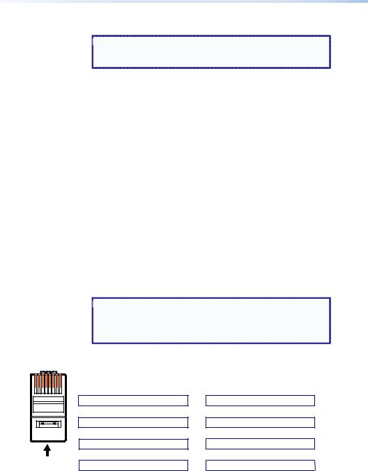
DEthernet port — If desired, connect the DXP switcher to a computer, a network WAN or LAN hub, or a control system via this RJ-45 connector. With the Ethernet connection, you can use a computer to control the networked switcher with SIS commands, the Matrix Switchers Control Program, or the embedded HTML pages on the switcher.
Ethernet connection indicators — The Link and Act LEDs indicate the status of the Ethernet connection.
•• Link: Indicates that the switcher is properly connected to an Ethernet LAN. This green LED should light steadily.
•• Act (Activity): Indicates transmission of data on the RJ-45 connector. This yellow LED should flicker as the switcher communicates.
Ethernet links use Category (CAT) 3, 5e, or 6 unshielded twisted pair (UTP) or shielded twisted pair (STP) cables, terminated with RJ-45 connectors. Ethernet cables are limited to 328 feet (100 m) .
 NOTES: • Do not use standard telephone cables. Telephone
cables do not support Ethernet or Fast Ethernet.
• Do not stretch or bend the cables because this can cause transmission errors.
Crossover Cable
|
End 1 |
End 2 |
Pin |
Wire Color |
Wire Color |
|
|
|
1 |
White-green |
White-orange |
2 |
Green |
Orange |
3 |
White-orange |
White-green |
4 |
Blue |
Blue |
5 |
White-blue |
White-blue |
6 |
Orange |
Green |
7 |
White-brown |
White-brown |
8 |
Brown |
Brown |
|
|
|
|
T568A |
T568B |
Straight-through Cable
Pin |
End 1 |
End 2 |
Wire Color |
Wire Color |
|
|
|
|
1 |
White-orange |
White-orange |
2 |
Orange |
Orange |
3 |
White-green |
White-green |
4 |
Blue |
Blue |
5 |
White-blue |
White-blue |
6 |
Green |
Green |
7 |
White-brown |
White-brown |
8 |
Brown |
Brown |
|
|
|
|
T568B |
T568B |
A cable that is wired as T568A at one end |
A cable that is wired the same at both ends |
and T568B at the other (Tx and Rx pairs |
is called a "straight-through" cable, because |
reversed) is a "crossover" cable. |
no pin or pair assignments are swapped. |
Figure 6. RJ-45 Connector and Pinout Tables
8 DXP DVI Pro and DXP HDMI Series • Setup

The cable you use depends on your network speed. The switcher supports both 10 Mbps (10Base-T — Ethernet) and 100 Mbps (100Base-T — Fast Ethernet) , half-duplex and full-duplex, Ethernet connections.
•• 10Base-T Ethernet requires CAT 3 or higher UTP or STP cable.
•• 100Base-T Fast Ethernet requires CAT 5e or higher UTP or STP cable.
Terminate the Ethernet cable as required:
•• Network connection — Wire as a patch (straight-through) cable.
•• Computer or control system connection — Wire as a crossover cable.
 NOTE: The factory default IP address is 192.168.254.254.
EReset LED — When the unit is being reset, this LED blinks the appropriate number of times to indicate the level of reset that has been performed.
FReset button — This recessed button initiates four levels (modes) of reset. Use a pointed object such as a small Phillips screwdriver or a stylus to press and hold the Reset button while the switcher is running or being powered up.
•• Hard reset (mode 1) — Hold the Reset button while powering up the switcher to restore the DXP to the default factory conditions. This reset restores the factory-installed firmware.
 NOTE: This type of reset does not clear the current
  configuration.
•• Events reset (mode 3) — Press and hold the Reset button for 3 seconds, then release and press it again momentarily to toggle events monitoring on and off.
•• IP settings reset (mode 4) — Press and hold the Reset button for 6 seconds, then release it and press it again momentarily to reset the switcher IP functions.
 NOTE: IP settings reset does not replace any user-installed
  firmware.
•• Absolute reset (mode 5) — Press and hold the Reset button for 9 seconds, then release it and press it again momentarily to restore the switcher to the default factory conditions.
For more details on these reset modes, see the DXP DVI Pro and DXP HDMI User Guide, available on the provided Extron Product Software DVD or the Extron website at www.extron.com.
DXP DVI Pro and DXP HDMI Series • Setup |
9 |
Loading...