


 Loading...
User Guide
Fiber Optic Matrix Switchers
FOX Matrix 3200,
FOX Matrix 7200
Configurable Fiber Optic Digital Matrix Switchers
68-1740-02 Rev. A
03 14

Safety Instructions
Safety Instructions • English
WARNING: |
This symbol, |
, when used on the product, is intended to |
alert the user of the presence of uninsulated dangerous voltage within the |
||
product’s enclosure that may present a risk of electric shock. |
||
ATTENTION: This symbol,  , when used on the product, is intended to alert the user of important operating and maintenance (servicing) instructions in the literature provided with the equipment.
For information on safety guidelines, regulatory compliances, EMI/EMF compatibility, accessibility, and related topics, see the Extron Safety and Regulatory Compliance Guide, part number 68-290-01, on the Extron website, www.extron.com.
Instructions de sécurité • Français |
|
|
AVERTISSEMENT: |
Ce pictogramme, |
, lorsqu’il est utilisé sur le |
produit, signale à l’utilisateur la présence à l’intérieur du boîtier du produit |
||
d’une tension électrique dangereuse susceptible de provoquer un choc |
||
électrique. |
|
|
ATTENTION: Ce pictogramme,  , lorsqu’il est utilisé sur le produit, signale à l’utilisateur des instructions d’utilisation ou de maintenance importantes qui se trouvent dans la documentation fournie avec le matériel.
Pour en savoir plus sur les règles de sécurité, la conformité à la réglementation, la compatibilité EMI/EMF, l’accessibilité, et autres sujets connexes, lisez les informations de sécurité et de conformité Extron, réf. 68- 290-01, sur le site Extron, www.extron.com.
Sicherheitsanweisungen • Deutsch
WARNUNG: Dieses Symbol |
auf dem Produkt soll den Benutzer darauf |
aufmerksam machen, dass im Inneren des Gehäuses dieses Produktes |
|
gefährliche Spannungen herrschen, die nicht isoliert sind und die einen |
|
elektrischen Schlag verursachen können. |
|
VORSICHT: Dieses Symbol  auf dem Produkt soll dem Benutzer in der im Lieferumfang enthaltenen Dokumentation besonders wichtige Hinweise zur Bedienung und Wartung (Instandhaltung) geben.
Weitere Informationen über die Sicherheitsrichtlinien, Produkthandhabung, EMI/EMF-Kompatibilität, Zugänglichkeit und verwandte Themen finden Sie in den Extron-Richtlinien für Sicherheit und Handhabung (Artikelnummer 68-290-01) auf der Extron-Website, www.extron.com.
Instrucciones de seguridad • Español
ADVERTENCIA: |
Este símbolo, |
, cuando se utiliza en el producto, |
avisa al usuario de la presencia de voltaje peligroso sin aislar dentro del |
||
producto, lo que puede representar un riesgo de descarga eléctrica. |
||
ATENCIÓN: Este símbolo,  , cuando se utiliza en el producto, avisa al usuario de la presencia de importantes instrucciones de uso y mantenimiento recogidas en la documentación proporcionada con el equipo.
Para obtener información sobre directrices de seguridad, cumplimiento de normativas, compatibilidad electromagnética, accesibilidad y temas relacionados, consulte la Guía de cumplimiento de normativas y seguridad de Extron, referencia 68-290-01, en el sitio Web de Extron, www.extron.com.
Инструкция по технике безопасности • Русский |
|||
ПРЕДУПРЕЖДЕНИЕ: |
Данный символ, |
, если указан |
|
на продукте, предупреждает пользователя о наличии |
|||
неизолированного опасного напряжения внутри корпуса |
|||
продукта, которое может привести к поражению |
|||
электрическим током. |
|
|
|
ВНИМАНИЕ: Данный символ, |
, если указан на продукте, |
||
предупреждает пользователя о наличии важных инструкций |
|||
по эксплуатации и обслуживанию в руководстве, |
|||
прилагаемом к данному оборудованию. |
|
||
Для получения информации о правилах техники безопасности, соблюдении нормативных требований, электромагнитной совместимости (ЭМП/ЭДС), возможности доступа и других вопросах см. руководство по безопасности и соблюдению нормативных требований Extron на сайте Extron: www.extron.com, номер по каталогу - 68-290-01.
Chinese Simplified |
|
|
 (
(
EMI/EMFExtron www.extron.com
Extron 68-290-01
Chinese Traditional |
) |
|
: |
|
|
|
||
|
|
|
|
|
|
EMI/EMF |
||
Extron www.extron.com Extron |
||
68-290-01 |
|
|
Japanese
: |
|
|
|
:  ( )
( )
EMI/EMF
www.extron.com Extron Safety and Regulatory Compliance Guide P/N( 68-290-01)
Korean |
|
: |
, |
|
|
. |
|
:  ,( ) .
, , EMI/EMF , ,Extron (www.extron.com) Extron, 68-290-01 .

FCC Class A Notice
This equipment has been tested and found to comply with the limits for a Class A digital device, pursuant to part 15 of the FCC rules. The Class A limits provide reasonable protection against harmful interference when the equipment is operated in a commercial environment. This equipment generates, uses, and can radiate radio frequency energy and, if not installed and used in accordance with the instruction manual, may cause harmful interference to radio communications. Operation of this equipment in a residential area is likely to cause interference. This interference must be corrected at the expense of the user.
Copyright
© 2014 Extron Electronics. All rights reserved.
Trademarks
All trademarks mentioned in this guide are the properties of their respective owners.
The following registered trademarks, registered service marks, and trademarks are the property of RGB Systems, Inc. or Extron Electronics:
Registered Trademarks (®)
AVTrac, Cable Cubby, CrossPoint, eBUS, EDID Manager, EDID Minder, Extron, Flat Field, GlobalViewer, Hideaway, Inline, IP Intercom,
IP Link, Key Minder, LockIt, MediaLink, PlenumVault, PoleVault, PowerCage, PURE3, Quantum, SoundField, SpeedMount, SpeedSwitch, System INTEGRATOR, TeamWork, TouchLink, V Lock, VersaTools, VN Matrix, VoiceLift, WallVault, WindoWall, XTP, and XTP Systems
Registered Service Mark(SM) : S3 Service Support Solutions
Trademarks (™)
AAP, AFL (Accu Rate Frame Lock), ADSP (Advanced Digital Sync Processing), Auto Image, CDRS (Class D Ripple Suppression), DDSP (Digital Display Sync Processing), DMI (Dynamic Motion Interpolation), Driver Configurator, DSP Configurator, DSVP (Digital Sync Validation Processing), FastBite, FOXBOX, IP Intercom HelpDesk, MAAP, MicroDigital, ProDSP, QS-FPC (QuickSwitch Front Panel Controller), Scope Trigger, SIS, Simple Instruction Set, Skew Free, SpeedNav, Triple Action Switching, XTRA, ZipCaddy, ZipClip
FDA/IEC 60825-1 Requirements
CLASS 1 LASER PRODUCT
Complies with FDA performance standards for laser products except for deviations pursuant to Laser Notice No. 5, dated June 24, 2007.
The product is intended to be used with the fiber optic cables fully installed.
This product meets the applicable requirements of IEC 60825-1, Edition 1 (2007).
Any service to this product must be carried out by Extron Electronics and its qualified service personnel.
NOTE: For more information on safety guidelines, regulatory compliances, EMI/EMF compatibility, accessibility, and related topics, see the “Extron Safety and Regulatory Compliance Guide” on the Extron website.
FDA/IEC 60825-1 Prérequis
Produit laser de classe 1
Conforme aux standards de performance FDA pour les produits laser, sauf pour d’éventuelles modifications, conformément à la « Laser Notice » numéro 5, datant du 24 juin 2007.
Le produit est conçu pour être utilisé avec les câbles fibre optique entièrement installés. Ce produit répond aux prérequis applicables de l’IEC 60825-1, 1ère Édition (2007).
Si ce produit a besoin d’un quelconque entretient, celui-ci doit être fait par Extron Electronics et son personnel qualifié.
Remarque: Pour plus d'informations sur les directives de sécurité, les conformités de régulation, la compatibilité EMI/EMF, l'accessibilité, et les sujets en lien, consultez le « Informations de sécurité et de conformité Extron » sur le site internet d'Extron.

Conventions Used in this Guide
Notifications
The following notifications are used:
WARNING: A warning indicates a situation that has the potential to result in death or |
severe injury. |
ATTENTION: Attention indicates a situation that may damage or destroy the product or associated equipment.
NOTE: A note draws attention to important information.
TIP: A tip provides a suggestion to make working with the application easier.
Software Commands
Commands are written in the fonts shown here:
^AR Merge Scene,,Op1 scene 1,1 ^B 51 ^W^C [01]R000400300004000080000600[02]35[17][03]
E X1# *X1** X2%* X2** X2^ CE}
NOTE: For commands and examples of computer or device responses mentioned in this guide, the character “0” is used for the number zero and “O” represents the capital letter “o.”
Computer responses and directory paths that do not have variables are written in the font shown here:
Reply from 208.132.180.48: bytes=32 times=2ms TTL=32 C:\Program Files\Extron
Variables are written in slanted form as shown here: ping xxx.xxx.xxx.xxx —t
SOH R Data STX Command ETB ETX
Selectable items, such as menu names, menu options, buttons, tabs, and field names are written in the font shown here:
From the File menu, select New. Click the OK button.
Specifications Availability
Product specification are available on the Extron website, www.extron.com.


Contents
Introduction............................................................ |
1 |
About this Guide................................................. |
1 |
About the FOX Matrix Switchers.......................... |
1 |
Fiber Cable Transmission Modes..................... |
4 |
Features.............................................................. |
4 |
Installation.............................................................. |
7 |
Setup and Installation Checklist........................... |
7 |
Get Ready....................................................... |
7 |
Configure the Matrix Switcher.......................... |
7 |
Perform Physical Installation............................ |
7 |
Ancillary Operations......................................... |
7 |
Rear Panel Boards, Cabling, and Features.......... |
8 |
I/O Boards.................................................... |
10 |
Remote Port.................................................. |
13 |
Ethernet Connection..................................... |
13 |
Reset Button and LED................................... |
14 |
Switch Reference Connections...................... |
15 |
Power Supply Modules and Indicator |
|
LEDs............................................................ |
16 |
Cooling Fan assemblies................................. |
16 |
Front Panel Configuration Port.......................... |
17 |
Operation.............................................................. |
18 |
Front Panel Controls and Indicators................... |
18 |
Input and Output Buttons.............................. |
20 |
Control Buttons............................................. |
22 |
Power Indicators........................................... |
23 |
Button Icons.................................................. |
24 |
Rear Panel Power Indicators............................. |
24 |
Front Panel Operations...................................... |
25 |
Definitions..................................................... |
25 |
Power........................................................... |
26 |
Creating a Configuration................................ |
26 |
Viewing the Configuration.............................. |
31 |
I/O Grouping................................................. |
33 |
Using Presets................................................ |
37 |
Muting and Unmuting Outputs...................... |
39 |
Locking the Front Panel (Executive Mode)..... |
41 |
Performing a System Reset from |
|
the Front Panel............................................. |
41 |
Background Illumination................................ |
42 |
Selecting the Rear Panel Remote Port |
|
Protocol and Baud Rate............................... |
42 |
Reset Operations.............................................. |
43 |
Performing Soft System Resets |
|
(Resets 3, 4, and 5)...................................... |
45 |
Performing a Hard Reset (Reset 1)................ |
46 |
Troubleshooting................................................. |
46 |
Configuration Worksheets................................. |
47 |
Worksheet Example 1: System equipment.... |
47 |
Worksheet Example 2: Daily Configuration.... |
48 |
Worksheet Example 3: Test configuration...... |
49 |
Programming Guide........................................... |
52 |
Serial Ports....................................................... |
53 |
Ethernet (LAN) Port........................................... |
54 |
Default IP addresses..................................... |
54 |
Establishing a Connection............................. |
54 |
Connection Timeouts.................................... |
55 |
Number of Connections................................ |
55 |
Using Verbose Mode..................................... |
55 |
Host-to-Switcher Instructions............................ |
55 |
Switcher-initiated Messages.............................. |
56 |
Switcher Error Responses................................. |
57 |
Using the Command and Response Tables....... |
57 |
Command and Response Table for SIS |
|
Commands.................................................. |
58 |
Command and Response Table for IPand |
|
SNMP-Specific SIS Commands................... |
67 |
Special Characters............................................ |
70 |
FOX Matrix 3200 and 7200 Switchers • Contents |
vii |

...................................................Matrix Software |
71 |
Matrix Switchers Control Program..................... |
71 |
Software Operation via Ethernet.................... |
71 |
Software Operation via a Serial Port.............. |
72 |
Installing the Software................................... |
72 |
Using the Matrix Switcher Control |
|
Software...................................................... |
73 |
Updating the Firmware.................................. |
80 |
Uploading HTML Files................................... |
84 |
Windows Buttons, Drop Boxes, and Trash Can. |
|
85 |
|
Using Emulation Mode.................................. |
89 |
Using the Help System.................................. |
90 |
Button Label Generator Program...................... |
91 |
Installing the Button Label Generator Software91 |
|
Using the Button Label Generator Software... |
92 |
|
|
HTML Operation.................................................. |
93 |
Opening the Embedded Web Pages................. |
94 |
Status Tab......................................................... |
95 |
System Status Page...................................... |
95 |
Input Link page............................................. |
96 |
Configuration Tab.............................................. |
97 |
System Settings Page................................... |
97 |
Passwords Page......................................... |
100 |
Email Settings Page.................................... |
101 |
SNMP Settings Page................................... |
103 |
Firmware Upgrade Page.............................. |
105 |
File Management Tab...................................... |
106 |
File Management Page................................ |
106 |
Control Tab..................................................... |
107 |
Set and View Ties Page.............................. |
107 |
Maintenance and Modifications.................... |
109 |
Mounting the Switcher.................................... |
109 |
UL Guidelines.............................................. |
109 |
Mounting Instructions.................................. |
110 |
Battery and Power Precautions....................... |
110 |
Removing and Installing the I/O Board |
|
or Blank Panel................................................ |
110 |
Removing the I/O Board or Blank Panel...... |
112 |
Installing the I/O board or blank panel......... |
112 |
Removing and Installing the Power Supply |
|
Module........................................................... |
113 |
Removing the Power Supply Module........... |
113 |
Installing the Power Supply Module............. |
113 |
Removing and Installing a Fan Module............ |
114 |
Removing a Fan Module.............................. |
114 |
Installing a Fan Module................................ |
114 |
Removing and Installing Button Labels............ |
115 |
Installing Labels in the Buttons.................... |
115 |
Ethernet Connection........................................ |
117 |
Ethernet Link................................................... |
117 |
Ethernet Connection................................... |
117 |
Default IP Address....................................... |
117 |
Pinging to Determine the |
|
Extron IP Address...................................... |
118 |
Pinging to Determine the |
|
Web IP Address.......................................... |
118 |
Configuring the Switcher for Network Use |
|
via the ARP Command............................... |
119 |
Connecting as a Telnet Client...................... |
120 |
Telnet Tips................................................... |
120 |
Subnetting — A Primer................................... |
122 |
Gateways.................................................... |
122 |
Local and Remote Devices.......................... |
122 |
IP Addresses and Octets............................. |
122 |
Subnet Masks and Octets........................... |
122 |
Determining Whether Devices Are |
|
on the Same Subnet.................................. |
123 |
FOX Matrix 3200 and 7200 Switchers • Contents |
viii |

Introduction
 WARNING: Risk of serious physical injury — The FOX matrix switchers fiber optic
I/O boards output continuous invisible light, which may be harmful to the eyes. Use
with caution.
• Do not look into the fiber optic cable connectors or into the fiber optic cables
themselves.
• Plug the attached dust caps into the optical transceivers when the fiber cable is unplugged.
•About this Guide
•About the FOX Matrix Switchers
•Features
About this Guide
This guide contains installation, configuration, and operating information for the Extron FOX Matrix 3200 Switcher and FOX Matrix 7200 Switcher. These customizable matrix switchers support up to 32 (FOX Matrix 3200) or 72 (FOX Matrix 7200) inputs and outputs.
NOTE: In this guide, “FOX matrix switcher” and “switcher” refer to either switcher model unless otherwise specified.
About the FOX Matrix Switchers
The FOX matrix switchers (see figure 1 on the next page) distribute optical and electronic input signals to one or more optical and electronic outputs. The matrix switchers can route multiple input/output configurations simultaneously. The switchers are configurable, assembled from individual input/output (I/O) boards, each of which supports 8 inputs by 8 outputs in a combination of the following types of board:
•Singlemode and multimode fiber optic I/O 88 reclocking boards — These non-pathologically-compliant fiber optic boards route signals that are compatible with all Extron FOX 500, FOXBOX, FOX II, and PowerCage FOX fiber optic product lines.
•FOX 3G I/O 88 SM P board — This pathologically-compliant fiber optic board passes digital signals in broadcasting applications, while addressing the compatibility issues of passing pathological signals generated from 3G-SDI, HD-SDI, and SDI signals over fiber optic systems.
•BNC 3G/HD/SD-SDI 88 I/O board — This pathologically-compliant board supports and passes 3G-SDI, HD-SDI, and SD-SDI signals in their native (electronic) format.
FOX Matrix 3200 and 7200 Switchers • Introduction |
1 |
POWER |
FOX HDSDI |
|
|
OPTICAL |
|
||
12V |
MODE |
|
|
0.3A MAX |
|
|
|
|
Tx |
Rx |
BUFFERED OUTPUTS |
FOX 3G HD-SDI
Singlemode
HDCAM
00:00:00:00 |
|
HD Camera |
|
POWER |
FOX HDSDI |
|
OPTICAL |
|
|
12V |
MODE |
|
0.3A MAX |
|
|
|
Tx Rx |
BUFFERED OUTPUTS |
FOX 3G HD-SDI
Multimode
|
|
OUT |
IN |
OUT |
IN |
OUT |
OUT |
IN |
OUT |
IN |
|
OUT |
IN |
OUT |
IN |
|
OUT |
IN |
OUT |
IN |
|
1 - 8 |
M |
|
|
|
|
|
|
|
|
|
|
|
|
|
|
|
|
|
|
ANAHEIM, CA |
|
|
A |
B |
|
|
|
C |
D |
|
|
E |
|
|
F |
|
|
G |
|
H |
|
|
|
|
|
|
|
|
|
|
|
|
|
|
|
|
|
|
|
|
|
|
9- 16 |
OUT |
IN |
OUT |
IN |
OUT |
OUT |
IN |
OUT |
IN |
|
OUT |
IN |
OUT |
IN |
|
OUT |
IN |
OUT |
IN |
|
S |
|
|
|
|
|
|
|
|
|
|
|
|
|
|
|
|
|
|
|
|
|
|
A |
B |
|
|
|
C |
D |
|
|
E |
|
|
F |
|
|
G |
|
H |
|
17 - 24 |
A |
B |
C |
|
D |
E |
F |
G |
H |
A |
B |
C |
D |
|
E |
F |
G |
H |
|
|
|
|
|
|
MUTI-RATE SDI INPUTS |
|
|
|
|
|
MUTI-RATE SDI OUTPUTS |
|
|
|
||||||
|
|
|
|
|
|
|
|
|
|
|
|
|
|
|||||||
|
- 32 |
A |
B |
C |
|
D |
E |
F |
G |
H |
A |
B |
C |
D |
|
E |
F |
G |
H |
|
|
D |
|
|
|
|
|
|
|
|
|
|
|
|
|
|
|
|
|
|
|
|
25 |
|
|
|
|
|
|
|
|
|
|
|
|
|
|
|
|
|
|
|
|
|
|
|
|
MUTI-RATE SDI INPUTS |
|
|
|
|
|
MUTI-RATE SDI OUTPUTS |
|
|
|
||||||
|
|
|
|
|
|
|
|
|
|
|
|
|
|
|||||||
|
|
100-240V |
50/60Hz 1.2A MAX. |
|
|
|
PRIMARY POWER SUPPLY |
|
|
|
|
|
|
REDUNDANT POWER SUPPLY |
|
|
||||
REMOTE RS-232/RS-422 |
TRI-LEVEL BI-LEVEL RESET |
DISCONNECT BOTH POWER CORDS BEFORE SERVICING |
PRIMARY REDUNDANT |
|
|
|
|
|
|
|
|
|
|
|
|
|
|
|
|
|
LAN ACT LINK |
|
|
|
|
|
|
|
|
|
|
|
|
|
|
|
|
|
|||
|
SWITCH |
100-240V |
50/60Hz 1.2A MAX. |
|
|
|
|
|
|
|
|
|
|
|
|
|
|
|
|
|
|
REFERENCE |
|
|
|
|
|
|
|
|
|
|
|
|
|
|
|
|
|
||
FOX Matrix 3200
HD-SDI Source 
M Multimode |
HD Camera |
|
|
I/O Board |
|
S |
Singlemode or |
HDCAM |
|
FOX 3G I/O 1616 SM P |
|
|
I/O Board |
00:00:00:00 |
D HD-SDI/HD-SDI/SDI |
|
|
|
I/O Board |
|
HD-SDI Source |
|
|
|
|
|
Singlemode |
|
|
|
Multimode |
|
NOTE: All FOX 3G HD-SDI units are set |
SDI/HD-SDI |
to bidirectional transceiver mode. |
|
|
|
|
HD-SDI
Monitor 
POWER |
FOX HDSDI |
|
|
OPTICAL |
|
||
12V |
MODE |
|
|
0.3A MAX |
|
|
|
|
Tx |
Rx |
BUFFERED OUTPUTS |
FOX 3G HD-SDI
Multimode
POWER |
FOX HDSDI |
|
|
OPTICAL |
|
||
12V |
MODE |
|
|
0.3A MAX |
|
|
|
|
Tx |
Rx |
BUFFERED OUTPUTS |
FOX 3G HD-SDI
Singlemode
HD Monitor
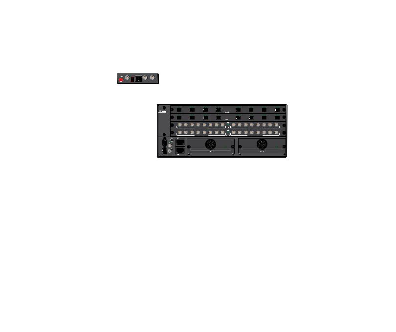
Figure 1. Typical FOX Matrix 3200 Application
NOTE: The non-pathologically-compliant multimode and singlemode fiber optic I/O boards are physically and functionally identical, with the exception of the effective range of transmission. In this guide, any reference to fiber optic transmission applies to either transmission mode unless otherwise specified. The pathologically-compliant fiber optic I/O board is identified separately where appropriate.
By adding or removing I/O boards, the FOX matrix switcher is expandable and contractable within the following ranges:
•FOX Matrix 3200 — Includes up to four I/O boards. It is expandable from an 8-input by 8-output matrix to a 32-input by 32-output matrix.
•FOX Matrix 7200 — Includes up to nine I/O boards. It is expandable from an 8-input by 8-output matrix to a 72-input by 72-output matrix.
The Extron proprietary fiber optic signal, generated by FOX 500, FOXBOX, PowerCage FOX, and FOX II transmitters, can include video, stereo audio, and transmitter-to-receiver RS-232 serial communications. The video component of the signal can be of a variety of formats, depending on the transmitter and receiver:
• |
RGB video |
• |
Digital Visual Interface (DVI) video |
|
• |
3G-SDI, HD-SDI, or SDI video |
• |
Low resolution (composite video or S-video) |
|
|
|
FOX Matrix 3200 and 7200 Switchers • Introduction |
2 |
|
NOTES:
•Compatible optical signals are digital signals from 270 Mbs through 4.25 Gbps, sent and received via fiber optic small form factor pluggable (SFP) modules. The FOX matrix switchers support all compatible optical signals, whether transmitted or received by an Extron FOX system component or not.
•The Extron FOX transmitter-to receiver communications, including the serial link, occupy one matrix switcher input and output. This matrix switcher also supports the Extron FOX return (receiver-to-transmitter) serial communications, but returning this signal stream to the transmitter uses a separate matrix switcher input and output.
The switchers input and output the optical signals that they route on fiber optic transceiver modules and the 3G-SDI, HD-SDI, and SDI video signals on BNC connectors.
The switcher has two 100 VAC to 240 VAC, 50-60 Hz, 175-watt power supplies that provide worldwide power compatibility and reliability.
The matrix switcher is a single box solution to complex fiber optic and broadcast signal routing applications. Each input and output is individually isolated and buffered. Any input can be switched to any one output or all outputs with virtually no crosstalk or signal noise between channels.
The matrix switcher can be remotely controlled using either the Extron Matrix Switchers Control Program or the Simple Instruction Set (SIS). Control is available via:
•A rear panel Remote RS-232/RS-422 port
•A rear panel LAN port
•A front panel RS-232 serial Config (configuration) port
The SIS is a set of basic ASCII code commands that provide simple control through a control system or PC without the need to enter long strings of code. SIS commands can be entered via any of the ports listed above.
The switcher can be operated remotely by any of the following connected to a serial port or LAN port:
•A control system
•A PC computer
•An Extron MKP 2000 or remote control panel
•An Extron MKP 3000 remote control panel
•(RS-232 or RS-422 only) An Extron MCP 1000 remote control panel, an MKP 1000 remote keypad, or both
The matrix switcher is housed in a rack-mountable, metal enclosure with mounting flanges for standard 19-inch racks. The sizes are as follows:
•FOX Matrix 7200 — 8U high
•FOX Matrix 3200 — 4U high
FOX Matrix 3200 and 7200 Switchers • Introduction |
3 |

Fiber Cable Transmission Modes
Two versions of non-pathologically-compliant FOX matrix switcher fiber optic I/O board are documented in this guide. They are categorized by the type of fiber optic cable, multimode or singlemode, which defines the effective range of transmission:
•Multimode — Long distance, up to 300 m (985 feet)
•Singlemode — Very long distance, up to 30 km (18.75 miles)
NOTES:
•All transceiver modules on a fiber optic I/O board, as delivered from Extron, are configured the same; either all multimode or all singlemode.
•You can mix multimode and singlemode fiber optic I/O boards in a FOX matrix switcher, but you must ensure that you connect the proper transmission mode fiber cables to the board.
Features
Fiber optic inputs and outputs — With fiber optic I/O boards, the switchers input and output fiber optic signals on SFP optical connectors. The fiber optic I/O boards support digital signals from 270 Mbs through 4.25 Gbps.
SDI, HD-SDI, or 3G-SDI inputs and outputs — With SDI/HD-SDI I/O boards, the switchers input and output SDI and HD-SDI signals on BNC connectors. The
SDI/HD-SDI I/O boards support multi-rate SDI at rates up to 2.97 Gbps, and comply with SMPTE 259M-C, 292M, 424M, and ITU digital video standards.
Cross-format compatibility —
•An input on an SDI/HD-SDI I/O board can be tied to an output on a fiber optic I/O board.
•An input on a fiber optic I/O board can be tied to an output on an SDI/HD-SDI I/O board.
Switching flexibility — The switcher provides individually buffered, independent matrix switched outputs.
•Tie any input to any or all outputs.
•Quick multiple tie — Multiple inputs can be switched to multiple outputs simultaneously. This allows all displays (outputs) to change from source to source at the same time.
Input link detection — In critical environments or unmanned, remote locations, it may be vital to know that sources are active and switching. The switcher confirms that input sources are active by detecting light. Link detection provides instantaneous feedback via the serial ports or LAN port of the switcher. The input information can be displayed on any control system or in a Windows-based control program on a local-area network (LAN) or Internet (IP) connection.
Rooming — The switcher can be programmed to group multiple outputs to specific “rooms”, allowing them to have their own presets.
FOX Matrix 3200 and 7200 Switchers • Introduction |
4 |

Operational reliability — The FOX matrix switcher can support round-the-clock operation in mission-critical applications, using a combination of hot-swappable components and redundant power supplies.
•Field upgradable, hot-swappable modular design — You can repair, upgrade, reconfigure, or expand the matrix by simply installing a new I/O board or replacing a board of one type with one of another. Hot-swappable components let you replace any I/O board at any time without powering down the switcher.
•Power redundancy — The built-in redundancy ensures zero downtime and no loss of functionality through all but catastrophic power failure.
•Two AC power inputs — The switcher can remain powered through any power interruption short of a simultaneous loss of power on both power sources.
•Primary and redundant, hot-swappable power supplies — The hotswappable, externally mounted redundant power supply is configured to automatically take over the load from the primary supply in the case of a failure.
The complete power circuit, from the plug, through the power supply, to the insertion of the power onto the power distribution plane, is separate and redundant (see figure 2). If the installation includes uninterruptible or completely separate power sources, the switcher remains powered up through any power interruption except a simultaneous loss of power on both power sources.
AC |
|
|
|
|
|
|
AC |
|
Power |
|
|
|
|
|
|
|
Power |
|
|
|
|
|
|
|
|
|
|
|
|
|
|
|
|
|
|
Primary |
Redundant |
Power |
Power |
Supply |
Supply |
Figure 2. Redundant Power Supply Backs up Primary
The hot-swappable redundant power supply means no downtime for the switcher and no loss of functionality should one power supply fail. Should a primary power supply fail, the redundant power supply immediately assumes the load of the failed primary supply. A failed power supply is easily replaceable from the rear at any time without powering down the matrix and with no tools required.
•Ease of maintenance — A failed power supply can be easily replaceable from the rear at any time without powering down the matrix, and with no tools required.
•Power supply status LEDs — Front panel and rear panel LEDs indicate the status of the primary and redundant power supplies.
•Hot-swappable fans — The hot-swappable, externally mounted fans allow quick replacement to avert overheating in the case of a failure. Fans can be replaced without powering down the switcher.
•Operational flexibility — Operations such as input/output selection and setting of presets can be performed using a variety of local and remote control mechanisms:
•Front panel controller
•Windows-based Matrix Switchers Control Program
•Simple Instruction Set (SIS)
•Remote control panels and keypads
FOX Matrix 3200 and 7200 Switchers • Introduction |
5 |

SNMP support for remote monitoring — Supports the Simple Network Management Protocol (SNMP) internet-standard protocol, allowing IT personnel to manage devices on the IP network.
Laser controls — Non-pathologically-compliant fiber optic boards can be set, via SIS commands, to individually or globally disable the output laser drivers so that a driver does not output light. They can also be set, individually or globally, to automatic so that a driver turns on when a tie is made involving that driver or turns off when no tie is made.
Upgradeable firmware — The firmware that controls all switcher operation can be upgraded in the field via RS-232/RS-422 or Ethernet, without taking the switcher out of service. Firmware upgrades are available for download at www.extron.com, and can be installed using the Windows-based control program or the built-in HTML pages.
Labeling — The Button Label Generator software, available at www.extron.com, lets you create labels to place in the front panel I/O buttons, with names, alphanumeric characters, or color bitmaps for easy and intuitive input and output selection.
Global memory presets — 32 (FOX Matrix 3200) or 64 (FOX Matrix 7200) global memory presets are a time-saving feature that lets you set up and store input/output configurations in advance. You can then recall those configurations, when needed, with a few simple steps. The presets are available via front panel operation or serial port or Ethernet control.
Rack mounting — Rack mountable in any conventional 19-inch wide rack.
Front panel security lockout modes (Executive mode) — If a matrix switcher is installed in an open area, where operation by unauthorized personnel may be a problem, a security lockout mode can be implemented. When the front panel is locked, a special button combination or SIS command is required to unlock the front panel controller and make the front panel fully operational.
I/O grouping — Allows the matrix to be virtually divided into smaller subswitchers, making installation and control easier. I/O grouping limits the selection of inputs and outputs
to members of the same group. I/O grouping allows specific outputs, such as those designated for a specific purpose, to be grouped together.
Video genlock (SDI / HD-SDI inputs only) — Allows for vertical interval switching and enables smooth, seamless transitions when switching between synchronous video sources. Separate bi-level (SDI) and tri-level (HD-SDI) references are provided on two separate BNC connectors.
Permanent, rechargeable battery — The matrix switcher has a rechargeable lithium battery to track time of day when power is disconnected.
WARNING: Explosion hazard — Service note to Extron personnel: There is a |
danger of explosion if the battery is incorrectly replaced. Replace it only with the same |
or equivalent type recommended by the manufacturer. Dispose of used batteries |
according to the instructions of the manufacturer. |
ATTENTION: Non-Extron personnel must not attempt to remove the battery. Doing so will void the warranty.
FOX Matrix 3200 and 7200 Switchers • Introduction |
6 |

Installation
This section details the installation and configuration of the FOX Matrix Switchers, including:
•Setup and Installation Checklist
•Rear Panel Boards, Cabling, and Features
•Front Panel Configuration Port
Setup and Installation Checklist
Get Ready
Familiarize yourself with the FOX matrix switcher.
Obtain IP setting information for the matrix switcher from the local network administrator. Read the Ethernet Connection section, beginning on page 117.
Configure the Matrix Switcher
Install the desired I/O boards (page 110).
Perform Physical Installation
If desired, install the switcher in a rack (see Mounting the Switcher on page 109).If desired, create (Page 92) and replace (Page 115) button labels.
Cable input and output devices to the I/O boards (page 11).
If desired, connect computers or control systems to any of the remote control ports on the switcher (two serial ports [page 13 and page 17] and a LAN port [page 13]).
Connect power (page 16).
Test the switcher by creating a tie (page 27).
Ancillary Operations
Install the Matrix Switchers Control Program (page 72).
FOX Matrix 3200 and 7200 Switchers • Installation |
7 |
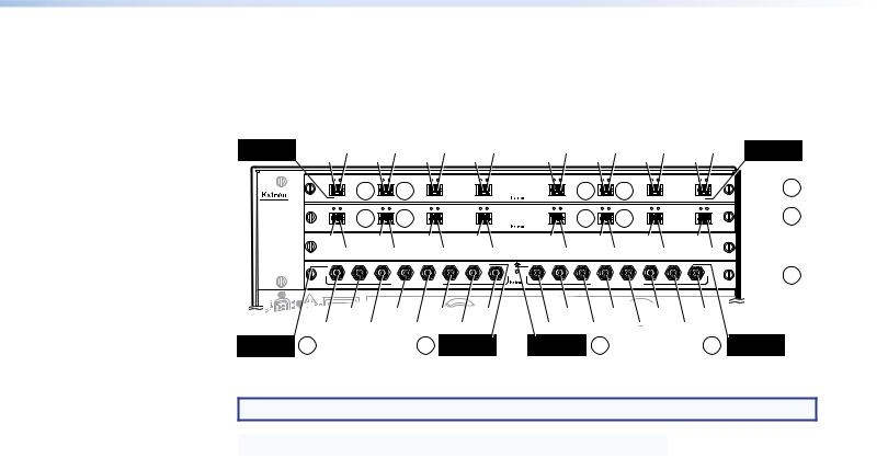
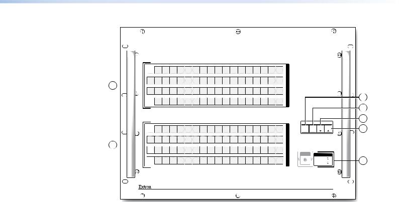
Rear Panel Boards, Cabling, and Features
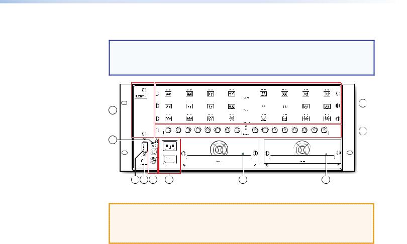
NOTE: Figure 3 shows a FOX Matrix 3200. Figure 4, on the next page, shows a FOX Matrix 7200. The two models have similar features, but are in different-sized
enclosures and the features are arranged differently. The FOX Matrix 7200 has two fan assemblies.
9 
5

 1
1
 2
2
REMOTE -232/RS- |
TRI-LEVEL BI-LEVEL RESET |
DISCONNECT BOTH POWER CORDS BEFORE SERVICING |
|
|
|
|
|
|
|
|
|
|
|
|
|
|
|
|
|
|
|
||||
|
|
|
|
|
|
|
|
|
||||
|
|
|
|
|
|
|
|
|
|
|
||
|
|
|
|
|
|
|
|
|
|
|||
|
|
|
|
|
|
|
|
|
|
|
||
|
|
|
|
|
|
|
|
|
|
|||
|
|
|
|
|
|
|
|
|
|
|
|
3 |
4 |
6 |
7 |
8 |
8 |
Figure 3. FOX Matrix 3200 Fiber Optic Matrix Switcher Rear Panel
ATTENTION:
•Use electrostatic discharge (ESD) precautions (be electrically grounded) when you make connections. ESD is damaging, even if you cannot feel, see, or hear it.
•Remove system power before making all connections
AFiber optic boards with connectors and LEDs (see page 11)
B3G-SDI, HD-SDI, and SDI boards with connectors and LEDs (see page 12)
CRemote RS-232 / RS-422 port (see page 13)
DEthernet connection (LAN connector) (see page 13)
EReset button (see page 14)
FSwitch Reference connectors (see page 15)
GPower connectors (see page 16)
HPower supply modules and indicator LEDs (see page 16)
ICooling fan assembly (see Removing and Installing a Fan Module on page 114)
FOX Matrix 3200 and 7200 Switchers • Installation |
8 |
9 |
|
|
|
|
|
|
|
|
1 |
|
|
|
|
|
|
|
|
OUT |
IN |
OUT |
IN |
OUT |
IN |
OUT |
IN |
OUT |
IN |
OUT |
IN |
OUT |
IN |
OUT |
IN |
|
1 - 8 |
|
|
|
|
|
|
|
|
|
|
|
|
|
|
|
FAN ASSIMBLY |
|
|
|
|
|
|
|
|
|
|
|
|
|
|
|
|
|
OUT |
IN |
OUT |
IN |
OUT |
IN |
OUT |
IN |
OUT |
IN |
OUT |
IN |
OUT |
IN |
OUT |
IN |
|
9 - 16 |
|
|
|
|
|
|
|
|
|
|
|
|
|
|
|
|
OUT |
IN |
OUT |
IN |
OUT |
IN |
OUT |
IN |
OUT |
IN |
OUT |
IN |
OUT |
IN |
OUT |
IN |
|
17 - 24 |
|
|
|
|
|
|
|
|
|
|
|
|
|
|
|
|
OUT |
IN |
OUT |
IN |
OUT |
IN |
OUT |
IN |
OUT |
IN |
OUT |
IN |
OUT |
IN |
OUT |
IN |
|
25 - 32 |
|
|
|
|
|
|
|
|
|
|
|
|
|
|
|
|
OUT |
IN |
OUT |
IN |
OUT |
IN |
OUT |
IN |
OUT |
IN |
OUT |
IN |
OUT |
IN |
OUT |
IN |
|
33 - 40 |
|
|
|
|
|
|
|
|
|
|
|
|
|
|
|
|
OUT |
IN |
OUT |
IN |
OUT |
IN |
OUT |
IN |
OUT |
IN |
OUT |
IN |
OUT |
IN |
OUT |
IN |
FAN ASSIMBLY |
41 - 48 |
|
|
|
|
|
|
|
|
|
|
|
|
|
|
|
|
OUT |
IN |
OUT |
IN |
OUT |
IN |
OUT |
IN |
OUT |
IN |
OUT |
IN |
OUT |
IN |
OUT |
IN |
|
49 - 56 |
|
|
|
|
|
|
|
|
|
|
|
|
|
|
|
|
57 - 64 |
|
|
MUTI-RATE SDI INPUTS |
|
|
|
|
MUTI-RATE SDI OUTPUTS |
|
|
2 |
||||
|
|
|
|
|
|
|
|
|
|
|||||||
|
65 - 72 |
|
|
|
|
|
|
|
|
|
|
|
|
|
|
|
|
|
|
MUTI-RATE SDI INPUTS |
|
|
|
|
MUTI-RATE SDI OUTPUTS |
|
|
|
|||||
|
|
|
|
|
|
|
|
|
|
|
||||||
|
|
|
|
|
|
|
|
|
|
|
|
REMOTE |
LAN |
|
SWITCH REFERENCE |
|
|
|
|
|
|
|
|
|
|
|
|
|
|
|
|
|
6 |
|
|
|
|
|
|
|
|
|
|
|
|
RS232/RS422 |
ACT LINK |
RESET |
BI-LEVEL |
TRI-LEVEL |
DISCONNECT BOTH POWER |
|
|
CORDS BEFORE SERVICING |
PRIMARY POWER SUPPLY |
REDUNDANT POWER SUPPLY |
|
REDUNDANT
100-240V 50/60Hz 1.2A MAX.
PRIMARY
100-240V 50/60Hz 1.2A MAX.
ANAHEIM, CA
7 |
8 |
3 |
4 |
5 |
8 |
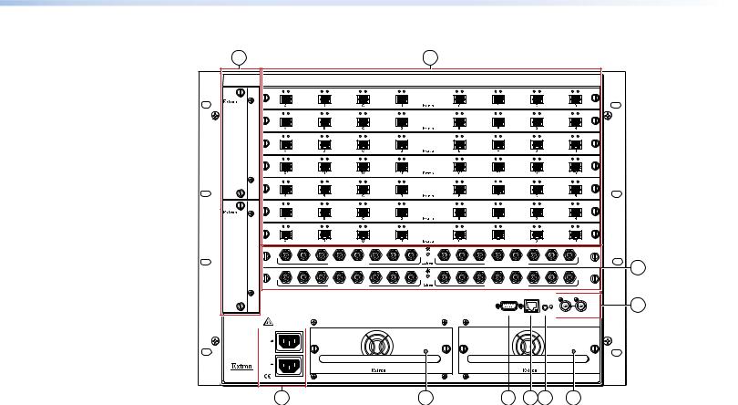
Figure 4. FOX Matrix 7200 Fiber Optic Matrix Switcher Rear Panel
AFiber optic boards with connectors and LEDs (see page 11)
B3G-SDI, HD-SDI, and SDI boards with connectors and LEDs (see page 12)
CRemote RS-232 / RS-422 port (see page 13)
DEthernet connection (LAN connector) (see page 13)
EReset button (see page 14)
FSwitch Reference connectors (see page 15)
GPower connectors (see page 16)
HPower supply modules and indicator LEDs (see page 16)
ICooling fan assembly (see Removing and Installing a Fan Module on page 114)
FOX Matrix 3200 and 7200 Switchers • Installation |
9 |
I/O Boards
As shown in figure 5, each I/O board is identified by the input and output numbers supported by the board position, which are printed on the side of each fan module (1 - 8, 9 - 16, and so on). The transceiver modules on fiber optic I/O boards are identified as A through H.
Location A |
I#1 O#2 I#2 O#3 |
I#3 O#4 I#4 |
O#5 I#5 O#6 I#6 O#7 I#7 O#8 I#8 |
Location H |
Output and Input O#1 |
Output and Input |
ANAHEIM, CA
Location A
Input
|
OUT |
IN |
OUT |
IN |
OUT |
IN |
OUT |
IN |
OUT |
IN |
OUT |
IN |
OUT |
IN |
OUT |
IN |
Slot 1 |
1 |
1 - 8 |
|
|
1a |
|
1b |
|
|
|
|
|
1a |
|
1b |
|
|
|
||
|
A |
|
B |
|
C |
|
D |
|
E |
|
F |
|
G |
|
H |
|
(1-8) |
|
9 - 16 |
OUT |
IN |
OUT |
IN |
OUT |
IN |
OUT |
IN |
OUT |
IN |
OUT |
IN |
OUT |
IN |
OUT |
IN |
Slot 2 |
1 |
|
|
1a |
|
1b |
|
|
|
|
|
1a |
|
1b |
|
|
|
|||
|
A |
|
B |
|
C |
|
D |
|
E |
|
F |
|
G |
|
H |
|
(9-16) |
|
- 24 |
O#9 |
|
O#10 |
|
O#11 |
|
O#12 |
|
O#13 |
|
O#14 |
|
O#15 |
O#16 |
|
Slot 3 |
|
|
|
|
|
|
|
|
|
No board |
|
||||||||||
17 |
|
I#9 |
I#10 |
I#11 |
I#12 |
|
I#13 |
I#14 |
I#15 |
I#16 |
|
|||||||
|
|
installed |
|
|||||||||||||||
2532 |
|
Slot 4 |
2 |
MUTI-RATE SDI INPUTS |
MUTI-RATE SDI OUTPUTS |
(25-32) |
|
100-240V |
50/60Hz 1.2A MAX. |
|
PRIMARY POWER SUPPLY |
|
|
|
REDUNDANT POWER SUPPLY |
|
|
|||
|
I#26 |
I#28 |
I#30 |
I#32 |
O#26 |
O#28 |
O#30 |
O#32 |
|
|||
I#25 |
I#27 |
I#29 |
I#31 |
|
O#25 |
O#27 |
O#29 |
O#31 |
|
|||
2a |
|
2a Location H |
Location A |
2b |
|
|
|
2b |
Location H |
|||
|
|
|
Input |
|
Output |
|
|
|
|
|
|
Output |
Figure 5. Arrangement of Inputs and Outputs on the I/O Boards
NOTE: The output on the transceiver module is to the left of the input.
Slot |
Inputs and Outputs |
Slot |
Inputs and Outputs |
|
|
|
|
1 |
1 through 8 |
5* |
33 through 40 |
|
|
|
|
2 |
9 through 16 |
6* |
41 through 48 |
|
|
|
|
3 |
17 through 24 |
7* |
49 through 56 |
|
|
|
|
4 |
25 through 32 |
8* |
57 through 64 |
|
|
|
|
|
|
9* |
65 through 72 |
|
|
|
|
* FOX Matrix 7200 only
Locations A through H correspond to the input and output numbers identified by the board position numbers. For example, the input and output numbers supported by the I/O board in location 9 - 16 (slot 2) are as follows: A = 9, B = 10, C = 11, D = 12, E = 13, F = 14,
G = 15, and H = 16.
On the fiber optic I/O boards, locations A through H correspond to the transceiver modules, each of which includes an input and an output. Therefore, locations A through H are numbered from left to right.
On the SDI/HD-SDI I/O boards, inputs and outputs are grouped separately, with inputs A through H on the left and outputs A through H on the right.
FOX Matrix 3200 and 7200 Switchers • Installation 10
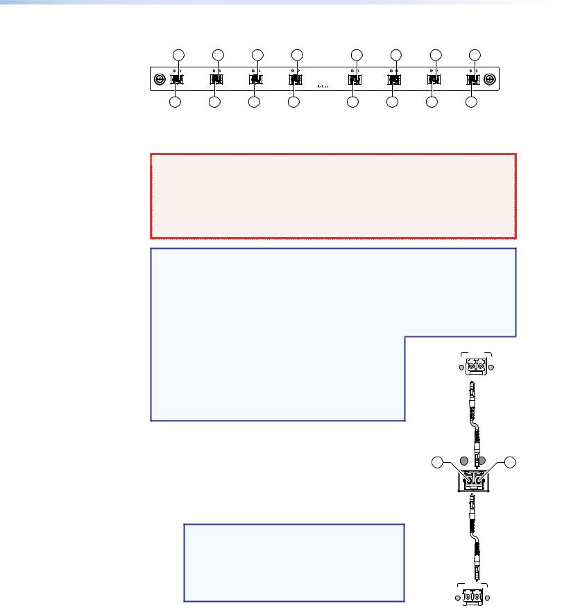
Fiber optic boards
1a |
1a |
1a |
1a |
1a |
1a |
1a |
1a |
OUT IN |
OUT IN |
OUT IN |
OUT IN |
OUT IN |
OUT IN |
OUT IN |
OUT IN |
A |
B |
C |
D |
E |
F |
G |
H |
1b |
1b |
1b |
1b |
1b |
1b |
1b |
1b |
Figure 6. Fiber Optic Board
A Fiber optic board, connectors (see figure 3 on page 8 and figure 4 on page 9) —
 WARNING: Risk of serious physical injury — The FOX matrix switchers fiber optic
I/O boards output continuous invisible light, which may be harmful to the eyes; use
with caution.
• Do not look into the fiber optic cable connectors or into the fiber optic cables.
• Plug the attached dust caps into the optical transceivers when the fiber cable is unplugged.
NOTES:
•Ensure that you use the proper fiber cable for your I/O board. Typically, singlemode fiber has a yellow jacket and multimode cable has an orange or aqua jacket.
•Unlike most Extron transmitters and receivers, which output an optical stream on one connector in a block and receive a return optical stream on the second connector in the same block, the FOX matrix switchers uses one connector on the block as an input and the second connector on the same block as a separate output.
•All transceiver modules on a fiber optic I/O board, as delivered from Extron, are configured the same: either all multimode or all singlemode.
•You can mix multimode and singlemode fiber optic I/O boards in a FOX matrix switcher, but you must ensure that you connect the proper transmission mode fiber cables to the board.
ÄInput connector and LED — For all one-way video, audio, and serial communications output by a transmitter, connect a fiber optic cable to the Input LC connector (see figure 7).
Connect the free end of this fiber optic cable to the Optical Tx LC connector on a FOXBOX Tx transmitter or to any other compatible fiber optic device.
NOTES:
•For a FOX 500 transmitter, connect this fiber optic cable to the Optical 1 LC connector.
•Alternatively, for the serial return, (receiver-to- transmitter) function, connect the far end of the cable to the Optical 2 connector on a receiver.
Extron |
Tx |
Rx |
Fiber Optic |
LINK |
LINK |
|
|
|
Transmitter |
|
|
Rx is optional connection
1b OUT |
IN 1a |
FOX
Matrix
Switcher
Tx is optional connection
Extron |
|
Tx Rx |
|
LINK |
LINK |
||
Fiber Optic |
|||
|
|
||
Receiver |
|
OPTICAL |
Input LED — See Fiber optic I/O board LED |
|
indications on the next page. |
Figure 7. Optical |
|
Connections |
FOX Matrix 3200 and 7200 Switchers • Installation 11
ÅOutput connector — For all one-way video, audio, and serial communications output to a receiver, connect a fiber optic cable to the Output LC connector (see figure 7, on the previous page).
Connect the far end of this fiber optic cable to the Optical Rx connector on a FOXBOX Rx receiver or to any other compatible fiber optic device.
NOTES:
•For a FOX 500 receiver, connect this fiber optic cable to the Optical 1 LC connector.
•Alternatively, for the serial return, (receiver-to-transmitter) function, connect the far end to the Optical RX or Optical 2 connector on a transmitter.
Output LED — See “Fiber optic I/O board LED indications,“ below.
Fiber optic I/O board LED indications
On the fiber optic I/O boards, the input and output LEDs on the transceivers provide useful indications of the status of the lasers and the reclocking function. See the table below.
|
OUT |
IN |
|
|
Output LED |
Input LED |
|
Definition |
indication |
indication |
Definition |
Reclocked at 4.25 Gbps |
On |
On |
Reclocked at 4.25 Gbps |
Not reclocked, laser off, or |
Off |
Off |
Not reclocked or no signal |
no signal |
|
|
|
Non-4G signal present or |
Fast blink |
Fast blink |
Non-4G signal present or |
not reclocked |
|
|
not reclocked |
NOTE: If the reclocking feature is set to bypass mode, the output LED is always on.
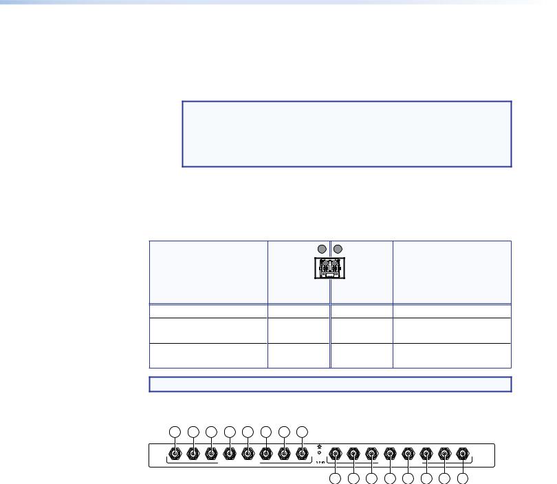
3G/HD/SD-SDI boards
2a 2a 2a 2a 2a 2a 2a 2a
MUTI-RATE SDI INPUTS |
MUTI-RATE SDI OUTPUTS |
2b 2b 2b 2b 2b 2b 2b 2b
Figure 8. 3G/HD/SD-SDI Board
BBNC board with connectors (see figure 3 on page 8 and figure 4 on page 9) —
ÇMulti-rate SDI Input connectors — Connect HD-SDI, SDI, or 3G-SDI video inputs to these BNC connectors.
ÉMulti-rate SDI Output connectors — Connect digital displays to these BNC connectors.
FOX Matrix 3200 and 7200 Switchers • Installation 12
Remote Port
CRemote RS-232/RS-422 connector (see figure 3 on page 8 and figure 4 on page 9) — Connect a host device, such as a computer or touch panel control, to the switcher via this 9-pin D connector for serial RS-232 or RS-422 control (see figure 9).
9 
RS-232/RS-422
REMOTE
6 
|
Pin |
RS-232 |
Function |
RS-422 |
Function |
|
|
1 |
— |
Not used |
— |
Not used |
|
|
2 |
Tx |
Transmit data |
Tx– |
Transmit data (–) |
|
5 |
3 |
Rx |
Receive data |
Rx– |
Receive data (–) |
|
4 |
— |
Not used |
— |
Not used |
||
|
||||||
1 |
5 |
Gnd |
Signal ground |
Gnd |
Signal ground |
|
6 |
— |
Not used |
— |
Not used |
||
|
7 |
— |
Not used |
Rx+ |
Receive data (+) |
|
|
8 |
— |
Not used |
Tx+ |
Transmit data (+) |
|
|
9 |
— |
Not used |
— |
Not used |
Figure 9. Remote RS-232/RS-422 Connector
See Programming Guide on page 52 for definitions of the SIS commands (serial commands to control the switcher via this connector) and Matrix Software on page 71 for details on how to install and use the control software.
NOTE: The switcher can support either the RS-232 or the RS-422 serial communication protocol, and can operate at 9600, 19200, 38400, or 115200 baud rates.
See the Command and Response Table for IPand SNMP-Specific SIS Commands on page 68 to configure this port under SIS control.
If desired, connect an MKP 2000 or MKP 3000 remote control panel to the Remote RS-232/RS-422 connector. See the MKP 2000 Remote Control Panel User Guide or the MKP 3000 User Guide for details.
Ethernet Connection
D LAN port (see figure 3 and figure 4) — For IP control of the system, connect the matrix switcher to a PC or to an Ethernet LAN via this RJ-45 connector. You can use a PC to control the networked switcher with SIS commands
from anywhere in the world. You can also control the switcher from a PC that is running the Extron Matrix Switchers Control Program or has downloaded HTML pages from the switcher.
Link LED indicator — The green (link) LED indicates that the switcher is properly connected to an Ethernet LAN. This LED should light steadily.
Act LED indicator — The yellow (activity) LED indicates transmission of data packets on the RJ-45 connector. This LED should flicker as the switcher communicates.
Cabling
It is vital that your Ethernet cables be the correct cable type and that they be properly terminated with the correct pinout. Ethernet links use Category (CAT) 3, 5e, or CAT 6, unshielded twisted pair (UTP) or shielded twisted pair (STP) cables, terminated with RJ-45 connectors. Ethernet cables are limited to a length of 328 feet (100 meters).
NOTES:
•Do not use standard telephone cables. Telephone cables do not support Ethernet or Fast Ethernet.
•Do not stretch or bend cables. Transmission errors can occur.
FOX Matrix 3200 and 7200 Switchers • Installation 13
The cable used depends on your network speed. The switcher supports both
10 Mbps (10Base-T — Ethernet) and 100 Mbps (100Base-T — Fast Ethernet), half-duplex and full-duplex Ethernet connections.
•10Base-T Ethernet requires CAT 3 UTP or STP cable at minimum.
•100Base-T Fast Ethernet requires CAT 5e UTP or STP cable at minimum.
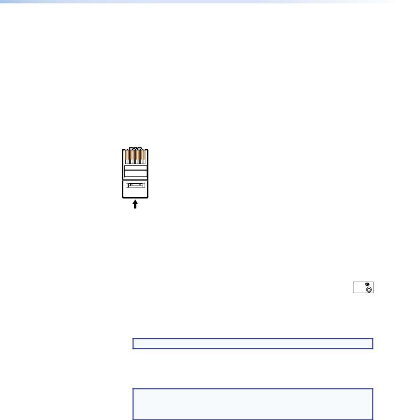
RJ-45 connector wiring
The Ethernet cable can be terminated as a straight-through cable or a crossover cable and must be properly terminated for your application (see figure 10).
•Crossover cable — Direct connection between the computer and the FOX matrix switcher
•Patch (straight) cable — Connection of the FOX matrix switcher to an Ethernet LAN
Pins:
12345678
Insert Twisted
Pair Wires
RJ-45
Connector
Crossover Cable
|
End 1 |
End 2 |
Pin |
Wire color |
Wire color |
|
|
|
1 |
White-green |
White-orange |
|
|
|
2 |
Green |
Orange |
|
|
|
3 |
White-orange |
White-green |
|
|
|
4 |
Blue |
Blue |
|
|
|
5 |
White-blue |
White-blue |
|
|
|
6 |
Orange |
Green |
|
|
|
7 |
White-brown |
White-brown |
|
|
|
8 |
Brown |
Brown |
|
|
|
|
T568A |
T568B |
A cable that is wired as T568A at one end and T568B at the other (Tx and Rx pairs reversed) is a "crossover" cable.
Straight-through Cable
Pin |
End 1 |
End 2 |
Wire color |
Wire color |
|
|
|
|
1 |
White-orange |
White-orange |
|
|
|
2 |
Orange |
Orange |
|
|
|
3 |
White-green |
White-green |
|
|
|
4 |
Blue |
Blue |
|
|
|
5 |
White-blue |
White-blue |
|
|
|
6 |
Green |
Green |
|
|
|
7 |
White-brown |
White-brown |
|
|
|
8 |
Brown |
Brown |
|
|
|
|
T568B |
T568B |
A cable that is wired the same at both ends is called a "straight-through" cable, because
no pin/pair assignments are swapped.
Figure 10. RJ-45 Connector and Pinout Tables
Reset Button and LED
E Reset button (see figure 3 on page 8 and figure 4 on page 9) — |
|
The recessed Reset button initiates four levels of matrix switcher reset. For four |
RESET |
|
different reset levels, press and hold the button while the switcher is running or while you power up the switcher (see Reset Operations on page 43 for details).
•Events (mode 3) reset — Toggles events monitoring on and off.
•IP settings (mode 4) reset — Reset the IP functions of the switcher.
NOTE: The IP settings reset does not replace any user-installed firmware.
•Absolute (mode 5) reset — Restore the switcher to the default factory conditions.
•Hard reset — Restore the switcher to the default factory conditions and return the switcher to the default firmware that shipped with the unit.
NOTES:
•Factory loaded firmware is active until it is replaced or the power is cycled.
•Hard reset does not clear the current configuration.
FOX Matrix 3200 and 7200 Switchers • Installation 14
Switch Reference Connections
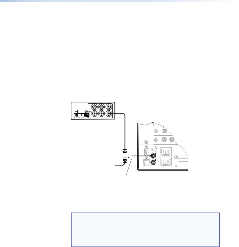
FSwitch Reference connectors for bi-level and tri-level sync (see figure 3 on page 8 and figure 4 on page 9) — (SDI / HD-SDI inputs and outputs only) Connect an external sync signal to this BNC connector to genlock the video signal in broadcast or other sync-critical applications.
The switcher makes ties to inputs on SDI/HD-SDI I/O boards during the vertical interval period of the tied video, resulting in glitch-free video switching when the input devices are also using the same sync timing. The FOX Matrix Switcher can use an external signal to synchronize switching during the vertical interval. Without this external sync locking feature, switching between inputs could result in brief video or picture rolling (sync loss) or a brief change in the picture size.
Figure 11 shows a basic external sync configuration. The Bi-level or Tri-level sync connector receives the timing signal. A tee connector attached to the cable allows the signal to be passed on to another video device, if required. Terminate the tee connector if desired.
BBG 6 A
BLACK BURST/COLOR BAR /AUDIO GENERATOR
POWER |
1 KHZ AUDIO |
NTSC |
|
12V |
+4dBu |
|
|
0.5A MAX |
L 1 R ON |
|
|
|
1 |
2 |
3 |
|
-10dBV PAL |
|
|
Extron
BBG 6 A
Black Burst, Color Bars,
and Audio Generator
1 |
3 |
5 |
|
|
OUT |
BLACKBURST/ 2 |
4 |
6 |
COLORBAR |
BLACKBURST |
|
Tee-connector 

Terminate cable or connect to another device.
Connect to
FOX Matrix 3200.
Extron
FOX Matrix 3200
Matrix Switcher
Figure 11. Simple FOX Matrix Switcher External Sync Connection Example
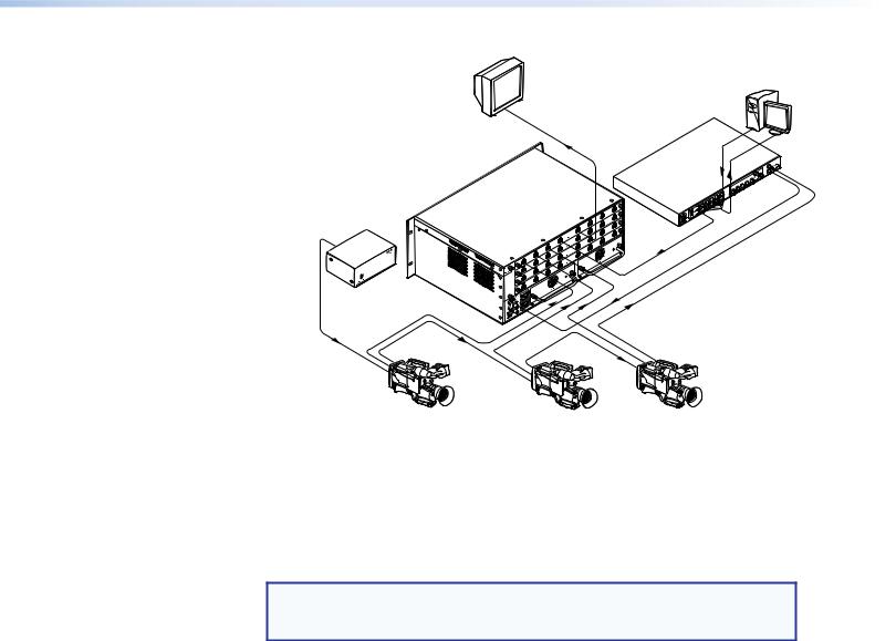
Figure 12 on the next page shows another configuration, in which the timing source passes through three video cameras and a video scan converter before connecting to the switcher. This type of video camera is capable of synchronizing with the external timing source for video editing applications.
NOTE: The Switch Reference connectors are tied into the I/O grouping feature of the switcher:
•Ties to any input in I/O group 1 use the tri-level sync reference.
•Ties to any output in I/O group 2 use the bi-level sync reference.
See I/O grouping on page 33 to assign sync-critical inputs and outputs to the appropriate I/O groups.
If no external sync timing source is connected to the switcher, switching occurs immediately.
FOX Matrix 3200 and 7200 Switchers • Installation 15
SDI/HD-SDI
Monitor
Extron
VSC 900D VGA Input
Computer-to-Video Scan Converter (SDI only)
|
Extron |
|
Extron |
FOX Matrix 3200 |
|
Matrix Switcher |
||
BBG 6 A |
||
|
||
Blackburst/Color Bars/ |
||
Audio Generator |
|
|
REMOTE 232/RS-RS -422 |
RESET |
LAN ACT LINK |
TRI-LEVELBILEVEL- |
SDI/HD-SDI |
SDI/HD-SDI |
SDI/HD-SDI |
Video Camera |
Video Camera |
Video Camera |
Figure 12. Multiple Device Example of a FOX Matrix 3200 External Sync
Power Supply Modules and Indicator LEDs
GPrimary and Redundant AC power connectors (see figure 3 on page 8 and figure 4 on page 9) — Plug standard IEC power cords into these connectors to connect the switcher to 100 VAC to 240 VAC, 50 or 60 Hz power sources.
NOTE: For the most reliable power, connect the power cord from the Redundant power connector to either an uninterruptible power source or to a power source that is completely independent from the primary power source.
HPrimary and Redundant power supply indicator LEDs (see figure 3 and figure 4) —
Green — Indicates that the associated power supply is operating within normal tolerances.
Red — Indicates that the associated power supply is operating outside the normal tolerances or has failed. See Removing and Installing a Power Supply Module on page 113 section to replace the power supply.
Cooling Fan assemblies
IPrimary and Redundant cooling fans (see figure 3 and figure 4) — Cool the equipment. If a fan has failed, replace it at your earliest opportunity. See Removing and Installing a Fan Module on page 114 to replace the fans.
FOX Matrix 3200 and 7200 Switchers • Installation 16
Front Panel Configuration Port
|
|
CONTROL |
|
|
CONFIG |
ENTER |
PRESET |
VIEW |
ESC |
PRIMARY
REDUNDANT
POWER SUPPLY
FOX 4G MATRIX 3200
FIBER OPTIC DIGITAL MATRIX SWITCHER
1
Figure 13. Front Panel Configuration (Config) Port
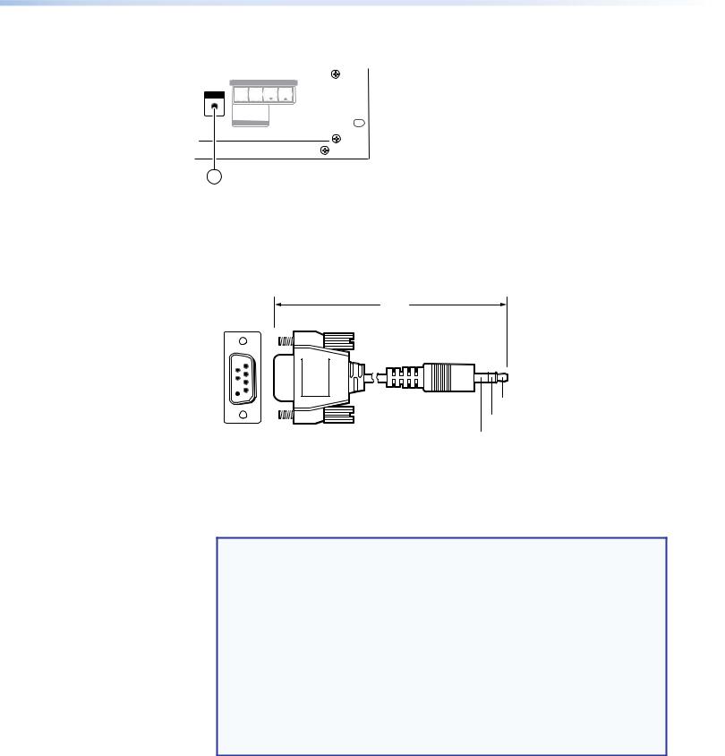
AConfiguration port — This 2.5 mm mini stereo jack serves the same serial communications function as the rear panel Remote port, but it is easier to access than the rear port after the matrix switcher has been installed and cabled. The optional 9-pin D to 2.5 mm mini jack TRS RS-232 cable (see figure 14) can be used for this connection.
6 feet
(1.8 m)
1
 6
6
 9 5
9 5 
Tip
Ring
Sleeve (Gnd)
9-pin D |
Connection |
TRS Plug |
Pin 2 |
Rx line on the computer |
Tip |
Pin 3 |
Tx line on the computer |
Ring |
Pin 5 |
Signal ground on the computer |
Sleeve |
Figure 14. Optional 9-pin TRS RS-232 Cable
NOTES:
•This port is independent of the rear panel Remote port and is not affected by changes to the protocol of the rear panel port. The protocol of the front panel port can be changed under SIS command control only. See the Command and Response table for IPand SNMP-Specific SIS commands on page 68 to configure this port under SIS control.
•A front panel Configuration port connection and a rear panel Remote port connection can both be active at the same time.
•The maximum distance from the matrix switcher to the controlling device can be up to 200 feet (61 meters). Factors such as cable gauge, baud rates,
environment, and output levels (from the switcher and the controlling device) all affect transmission distance. Distances of about 50 feet (15 meters) or less are typically not a problem. In some cases the matrix switcher may be capable of serial communications via RS-232 up to 250 feet (76 meters) away.
This port is RS-232 only, with its default protocols as follows:
• |
9600 baud |
• |
no parity |
• 8 data bits |
• |
1 stop bit |
• |
no flow control |
|
FOX Matrix 3200 and 7200 Switchers • Installation 17
Operation
This section describes the front panel operation of the FOX Matrix Switcher, including:
•Front Panel Controls and Indicators
•Rear Panel Power Indicators
•Front Panel Operations
•Reset Operations
•Troubleshooting
•Configuration Worksheets
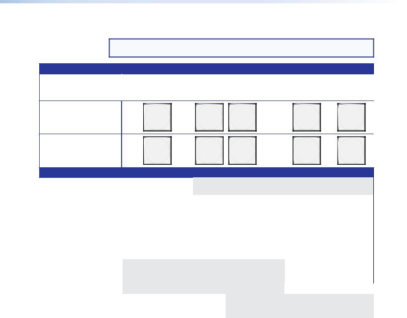
Front Panel Controls and Indicators
The front panel controls (see figure 15, below, and figure 16 on the next page) are grouped into two sets. The input and output buttons are grouped on the left side of the control panel. The control buttons are grouped on the right side of the panel.
|
|
|
|
|
|
|
INPUTS |
|
|
|
|
|
|
1 |
2 |
3 |
4 |
5 |
6 |
7 |
8 |
9 |
10 11 12 13 14 15 16 |
|
|
|
|
|
|
|
|
|
|
|
|
|
|
|
|
|
|
|
18 19 20 21 22 23 24 25 26 27 28 29 30 31 32 |
|
|
|
|
||||||||
|
2 |
3 |
4 |
5 |
6 |
7 |
8 |
9 |
10 11 12 13 14 15 16 |
|
|
|
|
2 |
|
|
|
|
|
|
|
|
CONFIG |
ENTER |
PRESET |
VIEW |
ESC |
18 |
19 20 21 22 |
23 24 25 26 27 28 29 30 31 32 |
|
|
|
|
|||||||
|
|
|
|
|
|||||||||
|
|
|
|
|
|
|
OUTPUTS |
|
|
|
|
|
|
|
|
|
|
|
|
|
|
|
|
|
|
|
FOX 4G MATRIX 3200 |
|
|
|
|
|
|
|
|
|
|
|
|
|
FIBER OPTIC DIGITAL MATRIX SWITCHER |
3
4
5
6
7
Figure 15. Front Panel, FOX Matrix 3200 Switcher
AInput buttons (see page 20).
BOutput buttons (see page 21).
CEnter button (see page 22).
DPreset button (see page 22).
EView button (see page 23).
FEsc button (see page 23).
GPrimary and Redundant Power Supply LEDs (see page 23).
FOX Matrix 3200 and 7200 Switchers • Operation 18
 2
2  3
3  4
4  5
5  6
6  7
7  8
8  9
9  10
10 11
11 12
12 13
13 14
14 15
15 16
16 17
17 18
18
20 21 22 23 24 25 26 27 28 29 30 31 32 33 34 35 36
1 


38 39 40 41 42 43 44 45 46 47 48 49 50 51 52 53 54
 56
56 57
57 58
58 59
59 60
60 61
61 62
62 63
63 64
64 65
65 66
66 67
67 68
68 69
69 70
70 71
71 72
72
 2
2  3
3  4
4  5
5  6
6  7
7  8
8  9
9  10
10 11
11 12
12 13
13 14
14 15
15 16
16 17
17 18
18
20 21 22 23 24 25 26 27 28 29 30 31 32 33 34 35 36
2 


 38 39 40 41 42 43 44 45 46 47 48 49 50 51 52 53 54
 56
56 57
57 58
58 59
59 60
60 61
61 62
62 63
63 64
64 65
65 66
66 67
67 68
68 69
69 70
70 71
71 72
72
I
N
P
U
T
S
|
|
|
|
|
3 |
|
|
|
|
|
4 |
|
|
|
|
|
5 |
|
|
|
|
|
|
|
|
|
|
|
6 |
|
ENTER |
PRESET |
VIEW |
ESC |
|
|
|
|
|
|
|
O
U
T
P
U
T
S
CONFIG
 7
7
FOX 4G MATRIX 7200
FIBER OPTIC DIGITAL MATRIX SWITCHER
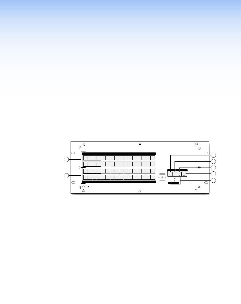
Figure 16. Front Panel, FOX Matrix 7200 Switcher
The illuminated pushbuttons can be labeled with either text or graphics. The buttons can be set to provide amber background illumination all the time or the background illumination can be turned off (see Background illumination, on page 42. The buttons blink or are lit at full intensity (depending on the operation) when selected.
AInput buttons (see page 20).
BOutput buttons (see page 21).
CEnter button (see page 22).
DPreset button (see page 22).
EView button (see page 23).
FEsc button (see page 23).
GPrimary and Redundant Power Supply LEDs (see page 23).
FOX Matrix 3200 and 7200 Switchers • Operation 19
Input and Output Buttons
NOTE: See Front Panel Operations on page 25 for detailed descriptions of the following operations.
Primary functions
|
Action |
Select input or output for tie being created. |
|
|
|
|
Indication |
Blink: potential tie/untie. |
|
|
Lit: current tie |
|
|
|
FOX Matrix 3200 |
1 |
2 |
3 |
31 |
32 |
|
|
|
|
|
|
|
1 |
2 |
3 |
through |
72 |
FOX Matrix 7200 |
71 |
||||
|
|
|
|
|
|
|
|
|
|
through |
|
Secondary functions
I/O grouping |
Action 1 |
Input 1 and Output 1: |
|
|
|
|
|
|
|
Select I/O Group mode. |
|
|
|
|
|
|
Action 2 |
Assign an input or output to the selected group. |
|
||||
|
Indication |
Lit: Input or output is assigned to the selected group. |
|
||||
|
|
|
|
|
|
|
|
Presets |
Action |
|
Select a preset in Preset mode. |
|
|||
|
|
|
|
|
|
|
|
|
Indication |
Lit: A preset has already been saved to this location. |
|
||||
|
|
Blink: Preset location is selected to be saved. |
|
||||
|
|
|
|
|
|
||
Output mutes |
Action |
Output buttons: Press and hold to mute or unmute the output. |
|
||||
|
|
|
|
|
|
|
|
|
Indication |
Output buttons blinking: Output is muted. |
|
||||
|
|
|
|
|
|
|
|
Port |
Action |
|
|
|
Output |
|
Output |
configuration |
|
|
|
|
31 or 71: |
|
32 or 72: |
|
|
|
|
|
Select RS-232. |
Select RS-422. |
|
|
Indication |
|
|
|
Blink: selected |
|
Blink: selected |
Background |
Action |
Input 1 and Input 2: |
|
|
|
|
|
illumination |
|
Toggle between background |
|
|
|
|
|
|
|
illumination or buttons unlit. |
|
|
|
|
|
|
|
|
|
|
|
|
|
AInput buttons — The input buttons have one primary function ( ) and four secondary functions (•):
Select and identify an input.
•(Input 1 only) With the Output 1 button, select I/O Group mode.
•Assign an input to the selected group in I/O Group mode and indicate its assignment.
•Select a preset.
•(Input 1 and Input 2 only) Toggle background illumination of the buttons on and off.
FOX Matrix 3200 and 7200 Switchers • Operation 20

BOutput buttons — The output buttons have one primary function ( ) and seven secondary functions (•):
Select and identify an output.
•(Output 1 only) With the Input 1 button, select I/O Group mode.
•Assign an output to the selected group in I/O Group mode and indicate its assignment.
•Select a preset.
•Mute the output.
•Output 31 (FOX Matrix 3200) or Output 71 (FOX Matrix 7200) — Select the RS-232 protocol for the RS-232/RS-422 port in Serial Port Selection and Configuration mode and indicate its selection.
•Output 32 (FOX Matrix 3200) or Output 72 (FOX Matrix 7200) — Select the RS-422 protocol for the RS-232/RS-422 port in Serial Port Selection and Configuration mode and indicate its selection.
FOX Matrix 3200 and 7200 Switchers • Operation 21
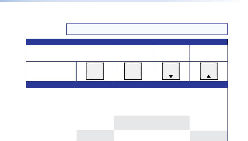
Control Buttons
NOTE: See Front Panel Operations on page 25 for detailed descriptions of the following operations.
Primary functions
|
Action |
Save changes |
Select Preset mode |
Select View mode |
Cancel/Escape |
|
|
|
|
|
|
|
|
|
Indication |
Blink: Save needed |
Blink: Save preset |
View mode selected |
Flashes once |
|
|
|
|
Lit: Recall preset |
|
|
|
|
|
|
|
|
|
|
ENTER |
PRESET |
VIEW |
ESC |
Secondary functions
I/O grouping |
Action/ |
Select and indicate |
Select and indicate |
Select and indicate |
Select and indicate |
|
|
indication |
group 1 |
group 2 |
group 3 |
group 4 |
|
|
|
|
|
|
|
|
Port |
Action 1 |
|
Select Configuration mode. |
|
|
|
configuration |
Action 2 |
Select 9600 baud |
Select 19200 baud |
Select 38400 baud |
Select 115200 baud |
|
|
|
|||||
|
Indication |
Blink: 9600 baud |
Blink: 19200 baud |
Blink: 38400 baud |
Blink: 115200 baud |
|
Front panel |
Action |
With Esc, toggle front |
|
|
With Enter, toggle |
|
lock |
|
panel lock on and off. |
|
|
front panel lock on |
|
|
|
|
|
|
and off. |
|
|
Action |
|
Flash twice to indicated the front panel has |
|
|
|
|
|
|
been locked or unlocked. |
|
|
|
|
|
|
|
|
|
|
CEnter button — The Enter button has two primary functions ( ) and three secondary functions (•):
Saves configuration or preset changes that you make on the front panel. To create a simple configuration:
Press the desired input button (item A).
Press the desired output button or buttons (item B).
Press the Enter button.
Indicates that a potential tie has been created but not saved.
•In the I/O Group mode, selects group 1 and indicates the selection.
•With the Preset, View, and Esc buttons, selects Serial Port Selection and Configuration mode.
•With the Esc button, toggles the front panel lock on and off.
DPreset button — The Preset button has two primary functions ( ) and three secondary functions (•):
Activates Save Preset mode to save a configuration as a preset and Recall Preset mode to activate a previously-defined preset.
Blinks when Save Preset mode is active and lights steadily when Recall Preset mode is active.
•In the I/O Group mode, selects group 2 and indicates the selection.
•With the Enter, View, and Esc buttons, selects Serial Port Selection and Configuration mode.
•Selects 19200 baud for the rear panel Remote port in Serial Port Selection and Configuration mode and indicates the selection.
FOX Matrix 3200 and 7200 Switchers • Operation 22
Loading...