


EVERFOCUS
1/3” Super High Resolution
560 TVL Day/Night
Dynamic Noise Reduction Camera
Operation Instructions
Model No. EQ550
Please read this manual first for correct installation and operation. This manual should be retained for future reference. The information in this manual was current when published. The manufacturer reserves the right to revise and improve its products. All specifications are therefore subject to change without notice.
PRECAUTIONS
1.Do not install the camera near electric or magnetic fields.
Install the camera away from TV, radio transmitter, magnet, electric motor, transformer, audio speakers since the magnetic fields generate from above devices will distort the video image.
2.Never disassemble the camera nor put impurities in it.
Disassembly or impurities may result in trouble or fire.
3.Never face the camera toward the sun.
Direct sunlight or severe ray may cause fatal damage to sensor and internal circuit.
4.Keep the power cord away from wet and never touch the power cord with wet hands.
Touch the wet power cord with hands or touch the power cord with wet hands may result in electric shock.
5.Never install the camera in areas exposed to water, oil or gas.
Water, oil or gas may result in failure, electric shock or file.
6.Cleaning
Do not touch the surface of sensor by hand directly. Use a soft cloth to remove the dirt from the camera body. Use lens tissue or a cotton tipped applicator and ethanol to clean the sensor and the camera lens.
7.Do not operate the camera beyond the specified temperature, humidity or power source ratings.
Use the camera at temperatures within 0 ~ 50 (32 ~122 ) and humidity between 20~80%. The input power source is 12VDC/24VAC or 100~ 240VAC.
TABLE OF CONTENTS |
|
1. PRODUCT OVERVIEW ................................................................................................................................... |
3 |
1.1 MAIN FEATURES .............................................................................................................................................. |
3 |
2. NAMES AND FUNCTIONS OF PARTS .......................................................................................................... |
4 |
2.1 FRONT PANEL................................................................................................................................................... |
4 |
2.2 TOP/BOTTOM ................................................................................................................................................... |
4 |
2.3 BACK PANEL CONNECTIONS ............................................................................................................................. |
5 |
3. INSTALLATION ................................................................................................................................................ |
7 |
4. CONNECTION................................................................................................................................................... |
8 |
5. CAMERA SETUP OPERATIONS .................................................................................................................... |
9 |
5.1 SETUP BUTTONS .............................................................................................................................................. |
9 |
5.2 DISPLAY/CLOSE THE USER SETUP MENU SCREEN............................................................................................ |
10 |
6. USER SETUP.................................................................................................................................................... |
11 |
6.1 LENS ............................................................................................................................................................ |
11 |
6.2 SHUTTER .................................................................................................................................................... |
11 |
6.3 WHITE BALANCE CONTROL ...................................................................................................................... |
13 |
6.4 BACKLIGHT ............................................................................................................................................... |
14 |
6.5 AGC (AUTO GAIN CONTROL)........................................................................................................................ |
14 |
6.6 DNR (DYNAMIC NOISE REDUCTION) ............................................................................................................ |
15 |
6.7 SENS-UP ...................................................................................................................................................... |
15 |
6.8 SPECIAL ...................................................................................................................................................... |
16 |
6.8.1 CAMERA ID .......................................................................................................................................... |
17 |
6.8.2 COLOR ADJ.......................................................................................................................................... |
18 |
6.8.3 SYNC ..................................................................................................................................................... |
18 |
6.8.4 MOTION DETECTION ......................................................................................................................... |
18 |
6.8.5 PRIVACY ............................................................................................................................................... |
21 |
6.8.6 MIRROR ................................................................................................................................................ |
23 |
6.8.7 SHARPNESS.......................................................................................................................................... |
23 |
6.8.8 RESET ................................................................................................................................................... |
24 |
6.8.9 RETURN................................................................................................................................................ |
24 |
6.9 EXIT ............................................................................................................................................................. |
24 |
7. POLESTAR WITH RS485 MINI DIN............................................................................................................ |
25 |
7.1 RS485 COMMUNICATION & CONTROL PIN.................................................................................................... |
25 |
7.2 KEY FEATURES WITH RS485.......................................................................................................................... |
26 |
7.3 HOW TO SET RS485 ID & BAUD RATE?.......................................................................................................... |
26 |
7.4 CONTROL BY KEYBOARD ............................................................................................................................... |
27 |
7.5 DAY/NIGHT MODE SETTING FROM KEYBOARD ............................................................................................... |
27 |
7.6 DAY/NIGHT CONTROL BY EXTERNAL D/N SIGNAL ......................................................................................... |
28 |
7.7 TO CONTROL EXTERNAL D/N SIGNAL............................................................................................................. |
28 |
7.8 ALARM OUTPUT FOR MOTION DETECTED ....................................................................................................... |
29 |
8. SPECIFICATIONS........................................................................................................................................... |
30 |
- 1 -
9. CONTENT LIST............................................................................................................................................... |
31 |
- 2 -
1. PRODUCT OVERVIEW
The new EQ550 Polestar is designed with advanced new generation 16-bit DSP which has powerful processing capability to show over 560TVL horizontal resolution. Built-in DNR (Dynamic Noise Reduction) function, the EQ550 performs clear & crisper image in low light and substantial disk-saving effect. In addition, designed with SENS-UP slow shutter technology, the starlight super-high sensitivity of 0.002 Lux is achieved. There are two models, one is Day/Night model, the other one is True Day/Night with ICR module. With RS485 port, you can even control EQ550 Polestar by a keyboard.
1.1Main Features
1/3” SONY Super HAD color CCD pick up device for more than 560 TV lines of horizontal resolution .
Advanced 16-bit Digital Signal Processor (DSP) delivers excellent picture quality and performance
Day/Night function (EQ550D)
True Day/Night function with ICR module (EQ550T)
Built-in DNR (Dynamic Noise Reduction) for noise reduction and a 70% saving of Disk storage
The starlight Super-high sensitivity of 0.002 Lux/F=1.2 is achieved by setting SENS-UP Shutter X128
0 Lux (IR LED on, if IR illuminator is used)
OSD setting menu
Support Motion Detection function
Provides alarm output for motion detected
Support Privacy function
High sensitivity designed with SONY sensor
Support either C-mount or CS-mount (Optional)
Support RS485 for keyboard control (for a certain protocol of keyboard only)
Receive external D/N signal to drive a synchronized control of Polestar’s D/N. (apply to housing that has IR LED)
Send out D/N signal to other external D/N control. (apply to housing that has IR LED)
- 3 -

2. NAMES AND FUNCTIONS OF PARTS
2.1 Front panel
Microphone (Reserved only for Audio model) |
Internal Sensor |
2.2 Top/Bottom
The bracket on the top side can be used for suspending the camera. On the other hand, the brackets on the bottom side can be used as a support of the camera.
Bottom Bracket
Top Bracket
- 4 -
2.3 Back panel connections
(12) |
(10) |
|
(4) |
|
|
|
(8) |
|
|
(7) |
||||
|
|
|
|
|
|
|
||||||||
|
|
|
|
|
|
|
|
|
||||||
|
|
|
485 |
|
|
|
|
|
|
|
|
|
||
(1) |
|
|
|
|
|
|
|
|
|
|
|
|
(6) |
|
|
|
|
|
|
|
|
|
|
|
|
|
|||
(9) |
|
|
|
|
|
|
|
|
|
|
|
(5) |
|
|
|
|
|
|
|
|
|
|
|
|
|
||||
|
|
|
|
|
|
|
|
|
|
|
(3) |
|
||
|
|
|
|
|
|
|
|
|
|
|
|
|||
|
|
|
|
|
|
|
|
|
|
|
||||
(11)
(2)
(13)
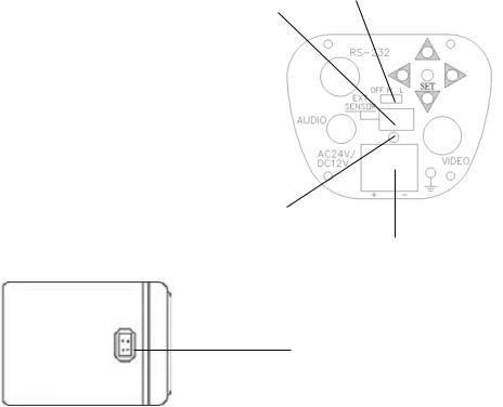
(1) RS-485 port
Connect to RS485 to get control by keyboard. Please refer to “6. Polestar with RS485 Mini Din” for detail about RS485 communication.
(2) Power Input Terminal
Connects to the appropriate power to each model.
(3) Video Output Connector
Connect the video output of the camera to a color monitor or other video devices through a 75 Ohm type coaxial cable with BNC female connector at backside of the camera.
(4)Tact switcher for left cursor
(5)Tact switcher for down cursor
(6)Tact switcher for right cursor
(7)Tact switcher for up cursor
(8)Tact switcher for on-screen setting menu
-5 -

(9)Audio Output Connector (for Audio model only)
(10)Switch:
For True Day/Night model with ICR (EQ550T)
H:IR cut filter is removed when illumination is low (about 5 Lux)
L:IR cut filter is removed when illumination is the lowest (Less than 2 Lux) OFF: Disable the function of IR cut removable
For Day/Night model without ICR (EQ550D)
H: Enabling the image to turn from color to B/W when the illumination is about 5 Lux
L: Enabling the image to turn from color to B/W when the illumination is about 2 Lux OFF: Day/Night function is disabled
(11) LED
RedPower on, GreenLow light condition detected.
1.IR cut filter will be removed in about 5-10 sec (for EQ550T).
2.Entering the Night mode, which makes the image to turn from color to B/W (for both EQ550D & EQ550T).
(12) External sensor connector
If user wants to change the location of IR light sensor, he/she can use an External light sensor to connect to this port. (Note: External light sensor kit is an optional product). When this External sensor port is used, the External sensor will be the default IR light sensor.
(13) Auto Iris Lens Connector
This connector is used to connect with the auto iris lens by a 4 pin male connector
Pin 1 |
Pin 2 |
Pin 3 |
Pin 4 |
3 |
4 |
||
Direct Drive Cnt- |
Cnt+ |
Drv+ |
Drv- |
||||
1 |
|
2 |
|||||
- 6 -

3. INSTALLATION
1.Remove the cover cap from the top of the lens mount.
2.If C mount lens is used, please add the C adaptor mount ring (the 5mm thick ring in the accessory pack) on top of the lens mount.
3.Mount the lens by turning it clockwise on the lens mount of the camera.
4.If you use the Auto Iris lens, connecting the lens cable to the auto iris lens connector on the side of the camera.
5.Place ND filter in front of the lens, adjust lens focus until best image is obtained.
6.Fix lens focus by turning tightly the swivel, then remove ND filter.
Mount the lens
Use ND filter
- 7 -
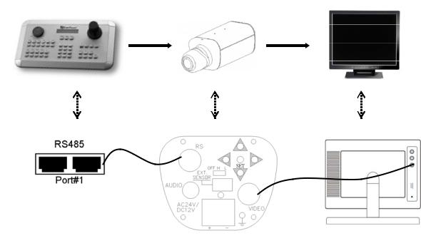
4. CONNECTION
485
1.Connect the cable from keyboard’s RS485 port to camera’s RS485 port.
2.Connect the cable from video output jack of the camera to monitor’s input jack.
3.RS485 ID of Polestar has to be the same as CAM ID of the keyboard. (Please refer to “6.3 How to set RS485 ID & Baud rate?” for RS485 ID setup detail)
4.Baud rate of Polestar has to be the same as Keyboard’s baud rate. (Please refer to “6.3 How to set RS485 ID & Baud rate?” for baud rate setup detail)
- 8 -
5. CAMERA SETUP OPERATIONS
This camera utilizes an On Screen Display (OSD) user setup menu.
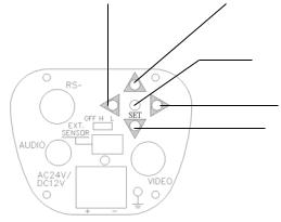
5.1 Setup Buttons
To set items on the user setup menu, use the following buttons on the back panel.
Left Button |
Up Button |
|
Set Button
485
Right Button
Down Button
Up Button: This button is used to move the cursor upwards. Use this button to select the item wanted to set.
Down Button: This button is used to move the cursor downwards. Use this button to select the item wanted to set.
Right Button: Use this button to select or adjust the parameters of the selected item. The parameter changes each time as this button is pressed.
Left Button: Use this button to select or adjust the parameters of the selected item. The parameter changes each time as this button is pressed.
Set Button: This button is used to enter setup menu. If the item has its own setting menu (sign ), press this button again to display the setup menu.
- 9 -
 Loading...