


 Loading...
Volume
1
Instruction Manual
EDSR400F/600F/
EDSR900F/1600F

E V E R F O C U S E L E C T R O N I C S C O R P O R A T I O N
EDSR 400F / EDSR600F
EDSR 900F / EDSR1600F
Instruction Guide
©2004 Everfocus Electronics Corp
2445 Huntington Drive
Phone 626.844.8888 • Fax 626.844.8838
All rights reserved. No part of the contents of this manual may be reproduced or transmitted in any form or by any means without written permission of the Everfocus Electronics Corporation.
QuickTime is a registered trademark of the Apple Computer, Inc. Windows is a registered trademark of the Microsoft Corporation in the United States and other countries. Linksys is a registered trademark of the Linksys Corporation. D-Link is a registered trademark of the D-Link Corporation. DynDNS is a registered trademark of the DynDNS.org Corporation. Other product and company names mentioned herein may be the trademarks of their respective owners.
Table of Contents
Introduction |
|
I |
C H A P T E R |
1 |
|
Product Overview |
1 |
|
Features |
|
1 |
Specifications |
|
2 |
Front Panel Keys |
3 |
|
Back Panel Keys |
5 |
|
C H A P T E R |
2 |
|
Installation |
|
7 |
Basic Wiring Instructions |
8 |
|
Hard Disk Drive Installation |
9 |
|
Final Install Process |
9 |
|
C H A P T E R |
3 |
|
DVR Menu Setup |
10 |
|
Clock/Language Setting Menu |
11 |
|
Timer Setting Menu |
13 |
|
Sequence Setting Menu |
15 |
|
Title Setting Menu |
17 |
|
Daylight Setting Menu |
15 |
|
Covert Setting Menu |
18 |
|
Alarm Record Setting Menu |
19 |
|
Motion Setting Menu |
21 |
|
Normal Record Setting Menu |
24 |
|
Network Setting Menu |
27 |
|
Control Setting Menu |
29 |
|
Buzzer Setting Menu |
32 |
|
Archive Setting Menu |
34 |
|
Matrix Setting Menu |
36 |
|
Disk Setting Menu |
38 |
|
System Setting Menu |
39 |
|
C H A P T E R |
4 |
|
Recording Overview |
42 |
|
Basic Recording Setup |
42 |
|
Timer Recording Setup |
43 |
|
Motion Recording Setup |
44 |
|
Alarm Recording Setup |
45 |
|
C H A P T E R |
5 |
|
Playback Overview |
47 |
|
Basic Playback |
|
47 |
Search Playback |
47 |
|
Segment List Playback |
47 |
|
Alarm List Playback |
49 |
|
Date/Time Playback |
50 |
|
C H A P T E R |
6 |
|
Copying Video |
|
51 |
Still Image Copy |
51 |
|
Copy as a MOV File |
52 |
|
Other Archiving Methods |
53 |
|
Viewing Copied Files |
54 |
|
C H A P T E R |
7 |
|
Audio Overview |
|
55 |
C H A P T E R |
8 |
|
How to Upgrade Firmware? |
56 |
|
C H A P T E R |
9 |
|
Networking Overview |
58 |
|
Introduction to TCP/IP |
58 |
|
Subnet Masks |
|
58 |
Gateway Address |
59 |
|
Virtual Ports |
|
59 |
Pre-Installation |
|
60 |
What type of Network Connection |
61 |
|
Simple One to One Connection |
62 |
|
Direct High Speed Modem Connection |
68 |
|
Router or LAN Connection |
70 |
|
C H A P T E R |
1 0 |
|
Linksys Port Forwarding |
73 |
|
Dynamic DNS |
|
77 |
C H A P T E R |
1 1 |
|
D-Link Port Forwarding |
79 |
|
Dynamic DNS |
|
82 |
C H A P T E R |
1 2 |
|
DDNS |
|
84 |
Creating a DDNS Account |
84 |
|
C H A P T E R |
1 3 |
|
Viewing through Internet Explorer |
87 |
|
C H A P T E R |
1 4 |
|
Interface Specifications |
91 |
|
Transmission Setting |
92 |
|
Remote Control Protocol |
92 |
|
A P P E N D I X |
A |
|
Remote Control |
|
95 |
A P P E N D I X |
B |
|
Time Lapse Recording Time |
96 |
|
A P P E N D I X |
C |
|
Alarm Board Configuration |
98 |
|
A P P E N D I X D |
|
RJ45 (RS485) Pin Assignment |
99 |
T R O U B L E S H O O T I N G |
|
Troubleshooting |
100 |

Currently, some Internet Service Providers (ISPs) may be blocking certain internet ports, disabling remote access to your EDSR unit over the internet. Due to certain security risks, your ISP may refuse to unblock these specific ports.
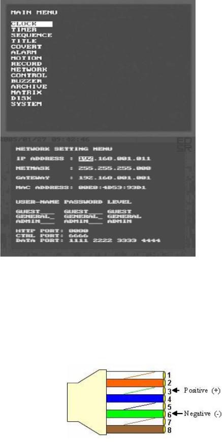
EverFocus now offers a firmware update specifically for the EDSR line of digital recorders which directly addresses this issue: firmware version 1.09 allows you to change the default HTTP and Data ports used by the DVR. This will provide a work around if your ISP refuses to unblock the ports on your internet connection. This feature is found in the NETWORK SETTINGS menu of your EDSR unit. This work-around allows you to customize your unit to connect using other various unblocked ports.
NOTE: For this work around, you will need to update to the latest firmware version, which can be found at: http://www.everfocus.com/servicebulletins.htm
HOW TO CHANGE PORTS ON AN EDSR 400-1600F:
1.) Access the Main Menu, by pressing [menu] on the front panel
2.) Use the JOG wheel to select NETWORK and press [ENTER]
3.) In the NETWORK SETTING MENU press [ENTER] until the Port Settings are reached.
4.) Use the JOG WHEEL to change the Ports as needed. (Only the CTRL port cannot be changed)
5.) Once the Ports are changed, press [MENU] twice to exit the menus and reboot the system.
Note: Once the Ports have been changed, these will be the ports that will need to be Forwarded if a NAT router (Linksys, Netgear, Dlink, etc.) is in use.
Due to all internet Browsers (Internet Explorer, Netscape Navigator, etc.) defaulting to use port 80 as the HTTP port; if the HTTP port number is changed from 80 to something else, the HTTP port must be specified when connecting to the DVR.
Example: IP address of the DVR is 146.82.96.172. ISP is blocking port 80, so HTTP port on DVR was changed to 1080, then the address that needs to be typed is
HTTP://146.82.96.172:1080. The :1080 entered at the end of the IP address specifies the port that the HTTP connection will be made.
PTZ control for EDSR Units.
The EDSR series Digital Recorders now offer PTZ control functions when using the web interface. You now have the same basic controls used with the VKB series keyboards over the web interface. This allows you to control the camera pan, tilt and zoom
functions while away.
Connections:
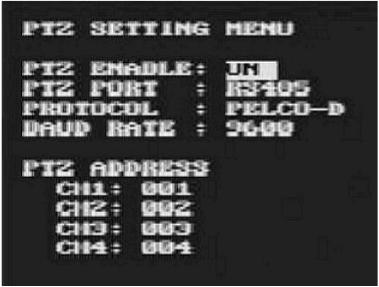
The Data Control cables connect to the back of the EDSR using the RS 485 Port. Depending on how your connections are setup and the number of cameras you are using, you will need to connect the data cables to Pins 3 and 6 on any of the 2 RS-485 ports. Pin 3 being Positive (+) and pin 6 being negative (-).
An Ethernet cable can be used in the RS485 port, as long as the wires for pin 3 and 6 are used. Looking at the top of an Ethernet cable, (flat edge) the wires that are used will be White-Green (3) and Green (6).
RJ-45 View from top– Locking clip is on reverse side.
EDSR PTZ setup.
Once the data cables are connected, the EDSR recorder is configured to communicate with PTZ camera or cameras.
Please Note: you need to determine what Protocol and Baud Rate is used for the cameras. (Note: All cameras connecting to the same DVR MUST be on the same Protocol and Baud Rate.)
SETTINGS:
1.) Access the Setup menu by pressing [MENU] on the front of the unit.
2.) Use the Jog Wheel to highlight the PTZ menu. Press[ENTER]
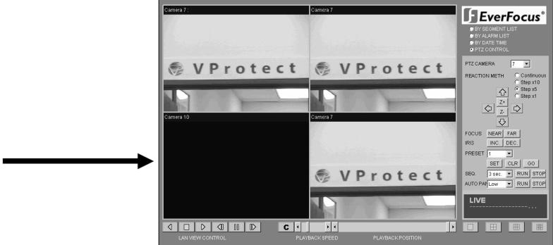
3.) In PTZ SETTINGS sub-menu, use [ENTER] to navigate between the options and the JOG WHEEL to change the settings.
4.) Set PTZ ENABLE: to ON,
5.) Set the PTZ port to RS485
6.) *Set the PROTOCOL to that of the Cameras (Pelco-D, Pelco-P, Everfocus, or VProtect)
7.) *Set the BAUD RATE to match that of the cameras
8.) Under PTZ ADDRESS, enter the Address for that camera on that specific channel. (Example: Channel 2 has a camera with Address 1, then for CH2: the value is change to 001, so it reads [CH2: 001].)
9.) Press [ENTER] twice to exit out of the setup menus. Restart the system.
*Note: These settings MUST match all the cameras connected on the same circuit.
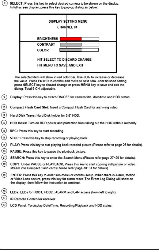
VIEWING
Once you access the unit via the web-page. The option for the PTZ controls will be on the Right Panel.

E V E R F O C U S E L E C T R O N I C S C O R P O R A T I O N
Chapter
1
Product Overview
DVRs are the industry’s first full-featured digital video recorder designed specifically for use within the security industry. The Digital Video Recorder incorporates all the benefits of digital video recording, is simple to install, and operates just like a VCR. Highly efficient compression technology and superior resolution of recorded images make the Digital Video Recorder stand out from the competition as the best choice for security surveillance.
Features
¾Easy-to-use control panel with common VCR and Multiplexer functions.
¾Shuttle/Jog dial for picture-by-picture or fast/slow viewing.
¾No tapes to manage, clean, or replace.
¾Instant retrieval of stored video.
¾On-screen setup menu and system timer.
¾Ethernet TCP/IP connectivity for remote viewing.
¾Pre-Alarm and Post-Alarm process.
¾Built-in M-JPEG compression/decompression with configurable quality.
¾Programmed with various time-lapse speeds.
¾3.5” IDE Type Hard Disks for storage with Hot-Swap tray.
¾RS232 and RS485 for Remote Control.
¾Real-Time Live Display for all Cameras.
¾Variable recording speeds up to 60/50 fps for NTSC/PAL.
¾Alarm-activated recording.
¾Data can be stored in a Compact Flash Card.
¾2 Channel real time audio recording capabilities.
1

E V E R F O C U S E L E C T R O N I C S C O R P O R A T I O N
Specifications
E V E R F O C U S E L E C T R O N I C S C O R P O R A T I O N
Front Panel Keypads
Keys:
E V E R F O C U S E L E C T R O N I C S C O R P O R A T I O N
E V E R F O C U S E L E C T R O N I C S C O R P O R A T I O N
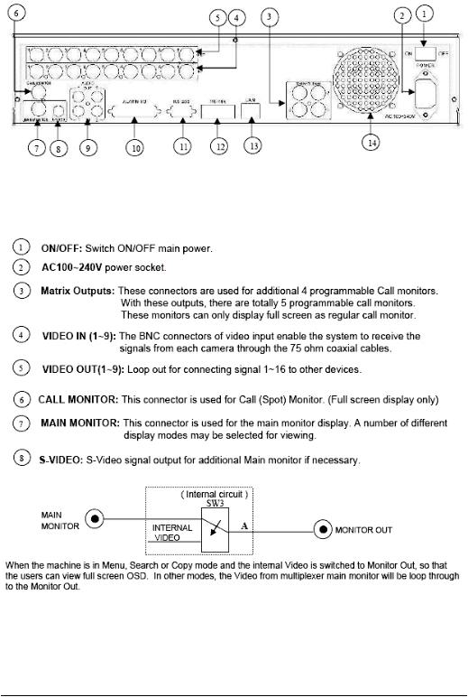
Back Panel Connections
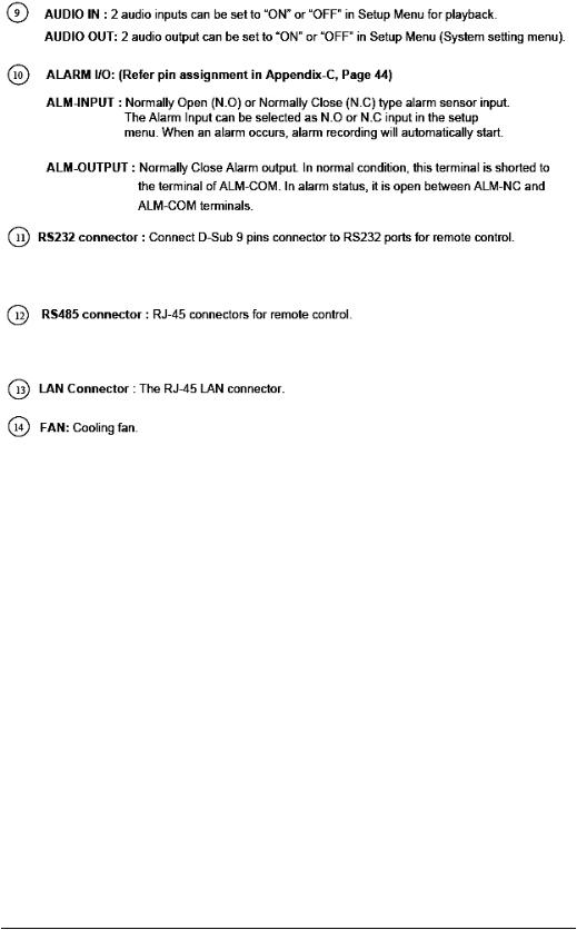
E V E R F O C U S E L E C T R O N I C S C O R P O R A T I O N
E V E R F O C U S E L E C T R O N I C S C O R P O R A T I O N
Chapter
2
Installation
The installations described below should be made by qualified service personnel or system installers.
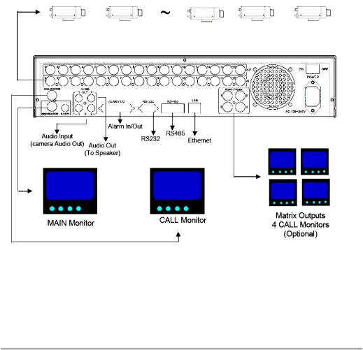
Please refer to the following diagram for the basic wiring connections.
¾ Please Note: Monitors and Cameras must be purchased separately.
EDSR400: Camera 1~4 / EDSR600: Camera 1~6
EDSR900: Camera 1~9 / EDSR1600: Camera 1~16
Diagram 1

E V E R F O C U S E L E C T R O N I C S C O R P O R A T I O N
Basic Wiring Instructions
Please refer to diagram 1 on page 9 to assist you with this portion of the installation.
¾Power: Connect the power source or adapter into the power socket shown in diagram 1.
Please Note: Do not plug the digital video recorder into the same power source as the cameras.
¾Cameras: Connect each cameras video output to the video input on the digital video recorder shown in diagram 1.
Please Note: At least one camera must be connected before the system is running for the auto detection of video standard to take effect.
¾Audio Input: The camera audio output or Microphone is connected to the audio input terminal at the rear panel.
¾Audio Output: Connect the speaker or other audio listening devices to the audio output terminal on the back of the digital video recorder.
¾Ethernet: The digital video recorder may be viewed from a PC via the LAN connector using a RJ45 Ethernet cable.
¾RS232/RS485: The digital video recorder may be controlled from a PC via RS232/RS485.
Please Note: This can be done using a serial cable.
¾Main Monitor: Connect the main monitor output connector to a main monitor. The main monitor displays selected live or recorded cameras in any available format.
Please Note: The main monitor must be connected in order to make configuration changes, enter the main menu, or do a playback at the machine.
¾Call and Matrix Monitors: Connect the call and matrix monitor output connectors to a call or matrix monitor. The call and matrix monitors display selected live cameras in full screen format.
Please Note: The call monitor will only display one full screen camera at a time.

E V E R F O C U S E L E C T R O N I C S C O R P O R A T I O N
Hard Disk Drive Installation
The first step in installing the hard drive is to insert the hard drive sleeve into the machine. The hard disk drive default setting is initially set to master. The second step is to insert the key provided and turn the tray key to the lock position. If this process is ignored the hard disk drive will not be detected. Follow the previous steps for the second hard drive or second empty sleeve.
Please Note: If the Hard Disk Drive is not locked in with the key a system loading screen will keep flashing and the DVR will not go into record mode. This is because the Hard Drive is not being recognized.
Final Install Process
Once you have completed the basic wiring installation and the hard disk drive installation you are read to turn on the DVR. Simply plug the power source you installed earlier. The POWER LED lights will light up if power is normal. The next step is to set up the menu options for the DVR.
E V E R F O C U S E L E C T R O N I C S C O R P O R A T I O N
Chapter
3
DVR Menu Setup
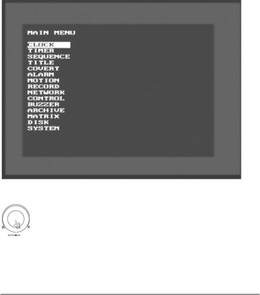
Assuming you have completed the first two chapters of this manual. You are now ready to begin setting up the digital video recorder menu. To begin this process, press the MENU key. Once inside the main menu you will find there are 15 setup option pages as follows.
Diagram 2
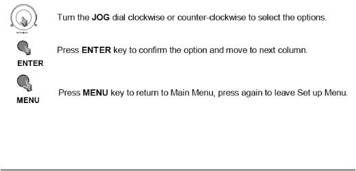
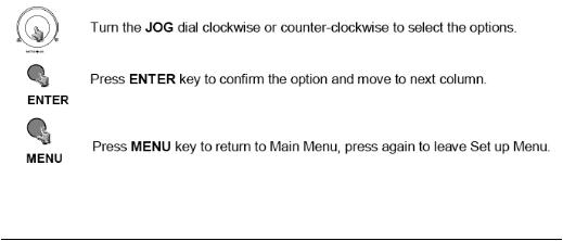
Turning the jog dial clockwise or counter clockwise will allow you to scroll through the different menu setup option pages.
E V E R F O C U S E L E C T R O N I C S C O R P O R A T I O N
Clock Setting Menu
Diagram 3
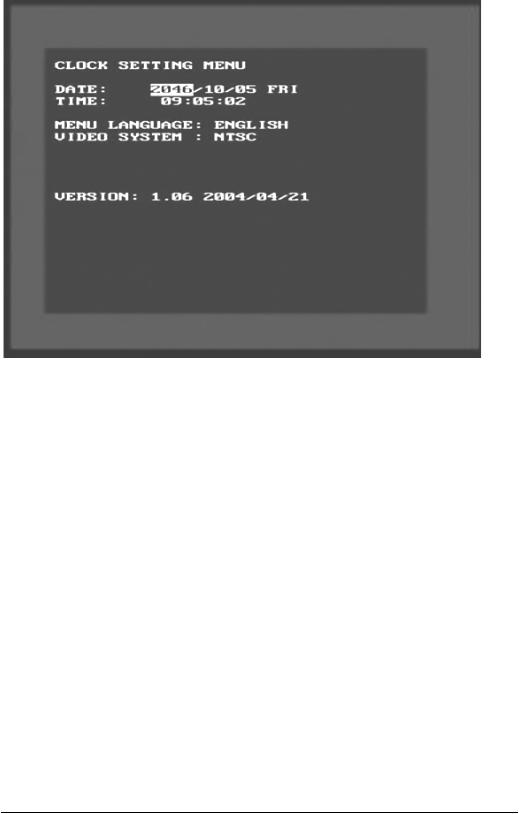
Diagram three is a screen shot of the Clock/Language Setting Menu. In the Clock/Language Setting Menu the following fields are defined as follows:
¾Date: This field represents the current date on the DVR. To change this, simply use the Jog Dial on the DVR. Press the Enter key to make your selection.
The date is represented as follows:
Year: 2000~2099 / Month: 01~12 / Date: 01~31 (Day of Week)
¾Time: This field represents the current time on the DVR which is in military time. To change this, simply use the Jog Dial on the DVR. Press the Enter key to make your selection.
The date is represented as follows:
Hour: 00~23 : Minute: 00~59 : Second: 00~59
E V E R F O C U S E L E C T R O N I C S C O R P O R A T I O N
¾Menu Language: This field is set to English from factory and can not be changed.
¾Video System: This field is set to NTSC from factory which is the North American Video Standard and can not be changed. The European and Asian Video Standards are PAL.
¾Version: This field represents the firmware version the digital video recorder is using.
Please Note: New firmware versions are available for download from
our ftp site. |
ftp://64.210.7.210 |
(see page for firmware |
upgrade instructions) |
|
|
¾ Release Date: This field represents the date the firmware was released.
E V E R F O C U S E L E C T R O N I C S C O R P O R A T I O N
Timer Setting Menu
Diagram 4
Diagram four is a screen shot of the Timer Setting Menu. In this menu you can set a unique timer any day of the week to start recording from a specified start time to an end time. In the Timer Setting Menu the following fields are defined as:
¾Week: This field represents the day of the week you wish to set the timer record for. Initially it is set to Sun as default. You may choose from MonSun as well as DLY. If you wish to create a daily timer for every day of the week you may choose the DLY option. To change this, simply use the Jog Dial on the DVR. Press the Enter key to make your selection.
¾Start: This field is used to set the time you wish to start the timer recording. To change this, simply use the Jog Dial on the DVR. Press the Enter key to make your selection.
¾Stop: This field is used to set the time you wish to stop the timer recording. To change this, simply use the Jog Dial on the DVR. Press the Enter key to make your selection.

E V E R F O C U S E L E C T R O N I C S C O R P O R A T I O N
Speed: This field is used to set the speed at which you would like the timer record to be recording at. To change this, simply use the Jog Dial on the DVR. Press the Enter key to make your selection.
Please Note: See Appendix B to find the appropriate speed to fit your recording needs.
Set: This field is used to turn the timer recording on or off. To change this, simply use the Jog Dial on the DVR. Press the Enter key to make your selection.
Please Note: If you wish to do any form of playback this feature must be turned off before attempting to playback.
E V E R F O C U S E L E C T R O N I C S C O R P O R A T I O N
Sequence Setting Menu
Diagram 5
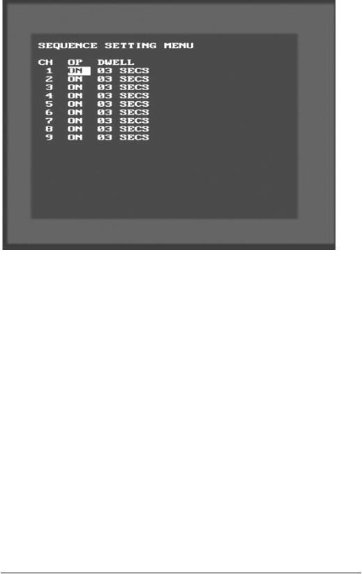
Diagram five is a screen shot of the Sequence Setting Menu. This menu is for setting up the way in which video is sequenced through the main monitor and call monitor outputs. In the Sequence Setting Menu the following fields are defined as follows:
Main Monitor: This field is to set the sequence for the main monitor output.
Channel: This field represents the channel you are setting to sequence.
Operation: This field is to turn on or off the camera for the sequence screen. The default is set to on. To change this, simply use the Jog Dial on the DVR. Press the Enter key to make your selection.
o Please Note: If an alarm occurs call monitor will display that particular camera automatically.
Dwell Time: This field represents the rate at which the cameras will sequence on the main monitor. The dwell time for the auto sequence
E V E R F O C U S E L E C T R O N I C S C O R P O R A T I O N
can be set from 0 to 99 seconds. To change this, simply use the Jog Dial on the DVR. Press the Enter key to make your selection.
E V E R F O C U S E L E C T R O N I C S C O R P O R A T I O N
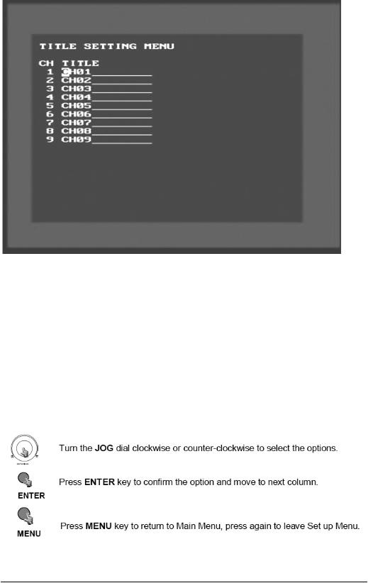
Title Setting Menu
Diagram 6
Diagram six is a screen shot of the Title Setting Menu. In this menu you can set a unique title for each of your cameras. To change this, simply use the Jog Dial on the DVR. Press the Enter key to make your selection.
¾ Example: |
|
|
CH1 |
: |
FrontDoor |
CH2 |
: |
BackDoor |
CH3 |
: |
Hallway |
CH4 |
: |
Closet |
E V E R F O C U S E L E C T R O N I C S C O R P O R A T I O N
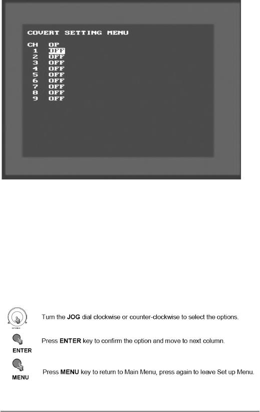
Covert Setting Menu
Diagram 7
Diagram seven is a screen shot of the Covert Setting Menu. In this menu you can set which cameras to be covert or hidden on the main monitor.
Channel: This field represents the channel you are setting to sequence.
Operation: This field is to turn on or off the camera for the sequence screen. The default is set to on. To change this, simply use the Jog Dial on the DVR. Press the Enter key to make your selection.
E V E R F O C U S E L E C T R O N I C S C O R P O R A T I O N
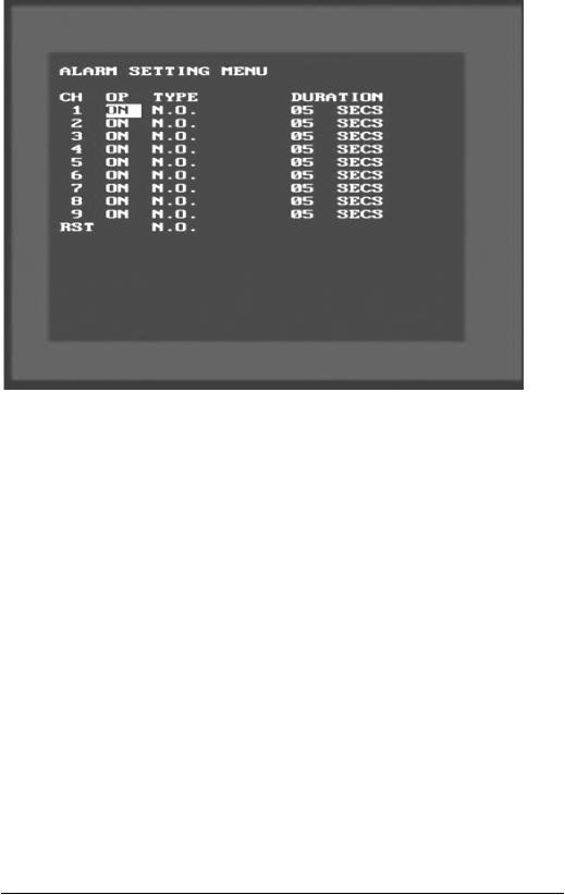
Alarm Setting Menu
Diagram 8
Diagram eight is a screen shot of the Alarm Record Setting Menu. This menu contains all the alarm operations and options needed to successfully complete an alarm recording. In the Alarm Record Setting Menu the following fields are defined as:
¾Operations: This field is to turn alarm recording on or off. The Default from the factory is set to on. To change this, simply use the Jog Dial on the DVR. Press the Enter key to make your selection.
¾Alarm Types: These fields represent what to do when a signal is received from the alarm board connector. There are two types of alarm signals. The first is N.O. which stands for Normally Open circuit. The Second is N.C. which stands for Normally Closed circuit. The default setting is N.O. This option would be set according to the type of alarm input connected to the alarm board. For example if you connected a door sensor which was a Normally Open circuit you would set the alarm type to N.O. To change this, simply use the Jog Dial on the DVR. Press the Enter key to make your selection.

E V E R F O C U S E L E C T R O N I C S C O R P O R A T I O N
Please Note: Refer to Appendix C for more information about setting up the alarm board.
Duration: When any sensor alarm connected to the device is activated, the device will immediately react with an alarm and display the warning message. This entry is used to set the alarm duration from 1 to 99 seconds. To change this, simply use the Jog Dial on the DVR. Press the Enter key to make your selection.
E V E R F O C U S E L E C T R O N I C S C O R P O R A T I O N
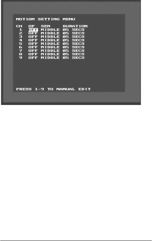
Motion Setting Menu
Diagram 9
Diagram nine is a screen shot of the Motion Setting Menu. This menu is for setting up the digital recorder for motion recording. In the Motion Setting Menu the following fields are defined as follows:
¾CH: This field represents the camera channels.
¾OP: This field is to set the option of turning motion on or off. If OP is turned on the DVR will respond by recording when motion occurs. If OP is turned off the DVR will not record when motion occurs. To change this, simply use the Jog Dial on the DVR. Press the Enter key to make your selection.
¾SEN: This entry signifies the sensitivity to pick up motion for each camera. There are four different sensitivity levels that can be used, High, Standard, Basic, Low. The default setting is standard. To change this, simply use the Jog Dial on the DVR. Press the Enter key to make your selection.
¾Duration: When any sensor alarm connected to the device is activated, the device will immediately react with an alarm and display the warning message. This entry is used to set the alarm duration from 1 to 99 seconds.
E V E R F O C U S E L E C T R O N I C S C O R P O R A T I O N
To change this, simply use the Jog Dial on the DVR. Press the Enter key to make your selection.
¾Manual Edit: This field represents manual editing of each camera for motion. To change this, simply use the Jog Dial on the DVR. Press the Enter key to make your selection. Use the jog dial to make your selection. Once you have chosen the channel you would like to manually edit, press the ENTER button. This will bring you to a new screen.
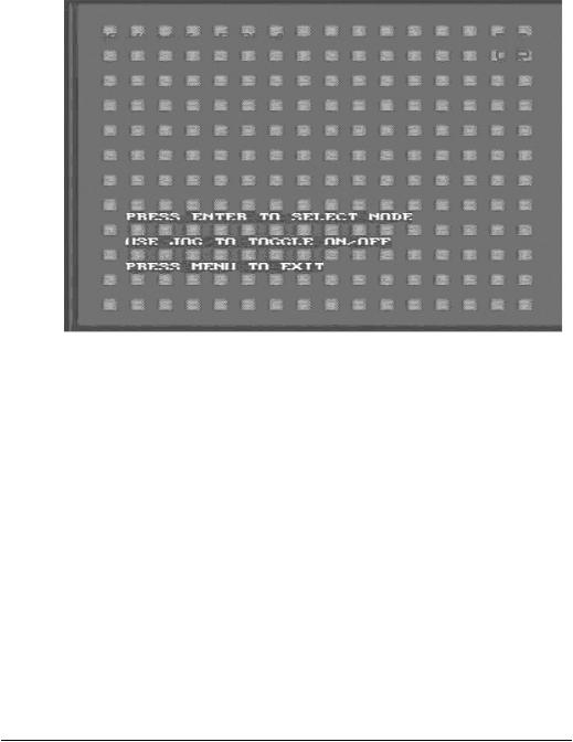
Diagram 10
¾Diagram 10 shows a screen shot of the manually edit screen. Use the arrow buttons to move through the squares. Initially all the squares are pink in color signifying that these squares are set up to pick up motion. To deselect a square simply move over the square and press the ENTER button. Diagram 11 shows another screen shot of a manually edited screen after editing has been accomplished.
Loading...